
HCNA Routing&Switching之静态路由
前文我们聊到了路由的相关概念和路由基础方面的话题,回顾请参考https://www.cnblogs.com/qiuhom-1874/p/14947897.html;今天我们聊聊静态路由相关话题;
回顾:在网络通信中,两个路由器要想通信,前提是必须有通往对端的路由;可以说路由是网络通信的基础条件;路由有很多种类,不同种类的路由信息其特点,优缺点各不相同;最为简单的就是直连路由,生成直连路由的必须满足两个条件,第一对应接口必须配置ip地址,其次对应接口物理和协议必须处于up状态;优点是自动生成,管理员只需要把对应接口配置上相应的地址,连上网线,对应直连路由就可以生成;缺点:只能够到达路由器直连的网络,不能够到达非直连的网络;
实验:如下图,配置好各设备的接口ip地址以后,看看对应路由表的变化,看看pc5,pc7以及R1是否能够ping同pc6?
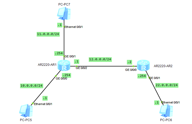
分析:要想pc5,pc7和R1和pc6通信,首先R1要有去往pc6的路由,其次pc5和pc7的网关指向R1,因为pc6和pc5pc7不在同一网络(不在同一网络的设备通信,默认将数据包发送给网关);
未配置R1各接口ip地址前的路由表
<Huawei>dis ip int b

*down: administratively down

^down: standby

(l): loopback

(s): spoofing

The number of interface that is UP in Physical is 4

The number of interface that is DOWN in Physical is 0

The number of interface that is UP in Protocol is 1

The number of interface that is DOWN in Protocol is 3

Interface                         IP Address/Mask      Physical   Protocol

GigabitEthernet0/0/0              unassigned           up         down

GigabitEthernet0/0/1              unassigned           up         down

GigabitEthernet0/0/2              unassigned           up         down

NULL0                             unassigned           up         up(s)

<Huawei>dis ip rou

<Huawei>dis ip routing-table

Route Flags: R - relay, D - download to fib

------------------------------------------------------------------------------

Routing Tables: Public

         Destinations : 4        Routes : 4

Destination/Mask    Proto   Pre  Cost      Flags NextHop         Interface

      127.0.0.0/8   Direct  0    0           D   127.0.0.1       InLoopBack0

      127.0.0.1/32  Direct  0    0           D   127.0.0.1       InLoopBack0

127.255.255.255/32  Direct  0    0           D   127.0.0.1       InLoopBack0

255.255.255.255/32  Direct  0    0           D   127.0.0.1       InLoopBack0

<Huawei>
提示:可以看到在未配置接口ip地址前,查看路由表,路由表中只有回环接口的路由信息;查看接口简要信息也可以发现对应接口的物理状态是up的,协议状态是down,不满足生成直连路由的条件,所以路由表没有对应接口的路由信息;
配置R1
<Huawei>sys

Enter system view, return user view with Ctrl+Z.

[Huawei]sys R1

[R1]int g0/0/0

[R1-GigabitEthernet0/0/0]ip add 10.0.0.254 24

Jul  2 2021 23:00:05-08:00 R1 %%01IFNET/4/LINK_STATE(l)[0]:The line protocol IP on the interface GigabitEthernet0/0/0 has entered the UP state. int g0/0/1

[R1-GigabitEthernet0/0/0]

[R1-GigabitEthernet0/0/1]ip add 11.0.0.254 24

[R1-GigabitEthernet0/0/1]int g0/0/2

[R1-GigabitEthernet0/0/2]ip add 12.0.0.1 24

Jul  2 2021 23:00:05-08:00 R1 %%01IFNET/4/LINK_STATE(l)[1]:The line protocol IP on the interface GigabitEthernet0/0/1 has entered the UP state.

[R1-GigabitEthernet0/0/2]ip add 12.0.0.1 24

Jul  2 2021 23:00:07-08:00 R1 %%01IFNET/4/LINK_STATE(l)[2]:The line protocol IP on the interface GigabitEthernet0/0/2 has entered the UP state.

[R1-GigabitEthernet0/0/2]q

[R1]dis ip int b

*down: administratively down

^down: standby

(l): loopback

(s): spoofing

The number of interface that is UP in Physical is 4

The number of interface that is DOWN in Physical is 0

The number of interface that is UP in Protocol is 4

The number of interface that is DOWN in Protocol is 0

Interface                         IP Address/Mask      Physical   Protocol

GigabitEthernet0/0/0              10.0.0.254/24        up         up

GigabitEthernet0/0/1              11.0.0.254/24        up         up

GigabitEthernet0/0/2              12.0.0.1/24          up         up

NULL0                             unassigned           up         up(s)

[R1]dis ip rou

[R1]dis ip routing-table

Route Flags: R - relay, D - download to fib

------------------------------------------------------------------------------

Routing Tables: Public

         Destinations : 13       Routes : 13

Destination/Mask    Proto   Pre  Cost      Flags NextHop         Interface

       10.0.0.0/24  Direct  0    0           D   10.0.0.254      GigabitEthernet0/0/0

     10.0.0.254/32  Direct  0    0           D   127.0.0.1       GigabitEthernet0/0/0

     10.0.0.255/32  Direct  0    0           D   127.0.0.1       GigabitEthernet0/0/0

       11.0.0.0/24  Direct  0    0           D   11.0.0.254      GigabitEthernet0/0/1

     11.0.0.254/32  Direct  0    0           D   127.0.0.1       GigabitEthernet0/0/1

     11.0.0.255/32  Direct  0    0           D   127.0.0.1       GigabitEthernet0/0/1

       12.0.0.0/24  Direct  0    0           D   12.0.0.1        GigabitEthernet0/0/2

       12.0.0.1/32  Direct  0    0           D   127.0.0.1       GigabitEthernet0/0/2

     12.0.0.255/32  Direct  0    0           D   127.0.0.1       GigabitEthernet0/0/2

      127.0.0.0/8   Direct  0    0           D   127.0.0.1       InLoopBack0

      127.0.0.1/32  Direct  0    0           D   127.0.0.1       InLoopBack0

127.255.255.255/32  Direct  0    0           D   127.0.0.1       InLoopBack0

255.255.255.255/32  Direct  0    0           D   127.0.0.1       InLoopBack0

[R1]
提示:可以看到在r1上的各接口上正确的配置上ip地址信息以后,对应接口的协议状态就从down转变为up状态,同时路由表中也多了对应网络的路由信息;
配置R2
<Huawei>sys

Enter system view, return user view with Ctrl+Z.

[Huawei]sys R2

[R2]int g0/0/0

[R2-GigabitEthernet0/0/0]ip add 12.0.0.2 24

[R2-GigabitEthernet0/0/0]int g0/0/1

Jul  2 2021 23:05:39-08:00 R2 %%01IFNET/4/LINK_STATE(l)[2]:The line protocol IP on the interface GigabitEthernet0/0/0 has entered the UP state.

[R2-GigabitEthernet0/0/0]int g0/0/1

[R2-GigabitEthernet0/0/1]ip add 22.0.0.254 24

Jul  2 2021 23:05:40-08:00 R2 %%01IFNET/4/LINK_STATE(l)[3]:The line protocol IP on the interface GigabitEthernet0/0/1 has entered the UP state.

[R2-GigabitEthernet0/0/1]q

[R2]dis ip int b

*down: administratively down

^down: standby

(l): loopback

(s): spoofing

The number of interface that is UP in Physical is 3

The number of interface that is DOWN in Physical is 1

The number of interface that is UP in Protocol is 3

The number of interface that is DOWN in Protocol is 1

Interface                         IP Address/Mask      Physical   Protocol

GigabitEthernet0/0/0              12.0.0.2/24          up         up

GigabitEthernet0/0/1              22.0.0.254/24        up         up

GigabitEthernet0/0/2              unassigned           down       down

NULL0                             unassigned           up         up(s)

[R2]dis ip rout

[R2]dis ip routing-table

Route Flags: R - relay, D - download to fib

------------------------------------------------------------------------------

Routing Tables: Public

         Destinations : 10       Routes : 10

Destination/Mask    Proto   Pre  Cost      Flags NextHop         Interface

       12.0.0.0/24  Direct  0    0           D   12.0.0.2        GigabitEthernet0/0/0

       12.0.0.2/32  Direct  0    0           D   127.0.0.1       GigabitEthernet0/0/0

     12.0.0.255/32  Direct  0    0           D   127.0.0.1       GigabitEthernet0/0/0

       22.0.0.0/24  Direct  0    0           D   22.0.0.254      GigabitEthernet0/0/1

     22.0.0.254/32  Direct  0    0           D   127.0.0.1       GigabitEthernet0/0/1

     22.0.0.255/32  Direct  0    0           D   127.0.0.1       GigabitEthernet0/0/1

      127.0.0.0/8   Direct  0    0           D   127.0.0.1       InLoopBack0

      127.0.0.1/32  Direct  0    0           D   127.0.0.1       InLoopBack0

127.255.255.255/32  Direct  0    0           D   127.0.0.1       InLoopBack0

255.255.255.255/32  Direct  0    0           D   127.0.0.1       InLoopBack0

[R2]
提示:按照题意我们配置好了两个路由器的名称和相关接口的ip地址,对应路由器各自都生成了相应的直连路由;
配置好各pc的ip地址信息,然后用pc5ping pc6看看是否可以正常通信?
配置pc5

提示:pc5和R1的g0/0/0口是直连,所以对应pc5的网关必须指向R1的g0/0/0接口的ip地址;
配置pc6

提示:pc6和R2的g0/0/1口是直连,所以对应pc6的网关必须指向R2的g0/0/1接口的ip地址;
配置pc7
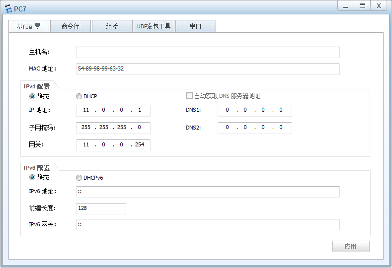
提示:pc7和R1的g0/0/1口是直连,所以对应pc7的网关必须指向R1的g0/0/1接口的ip地址;
验证:pc5 ping pc6看看是否可以通信?
PC>ipconfig

Link local IPv6 address...........: fe80::5689:98ff:fe54:5adc

IPv6 address......................: :: / 128

IPv6 gateway......................: ::

IPv4 address......................: 10.0.0.1

Subnet mask.......................: 255.255.255.0

Gateway...........................: 10.0.0.254

Physical address..................: 54-89-98-54-5A-DC

DNS server........................:

PC>ping 22.0.0.1

Ping 22.0.0.1: 32 data bytes, Press Ctrl_C to break

Request timeout!

Request timeout!

Request timeout!

Request timeout!

Request timeout!

--- 22.0.0.1 ping statistics ---

  5 packet(s) transmitted

  0 packet(s) received

  100.00% packet loss

PC>
提示:可以看到在pc5上ping pc6,给我们的回馈是请求超时;
在r1的g0/0/2口抓包,看看对应是否有数据包通过?
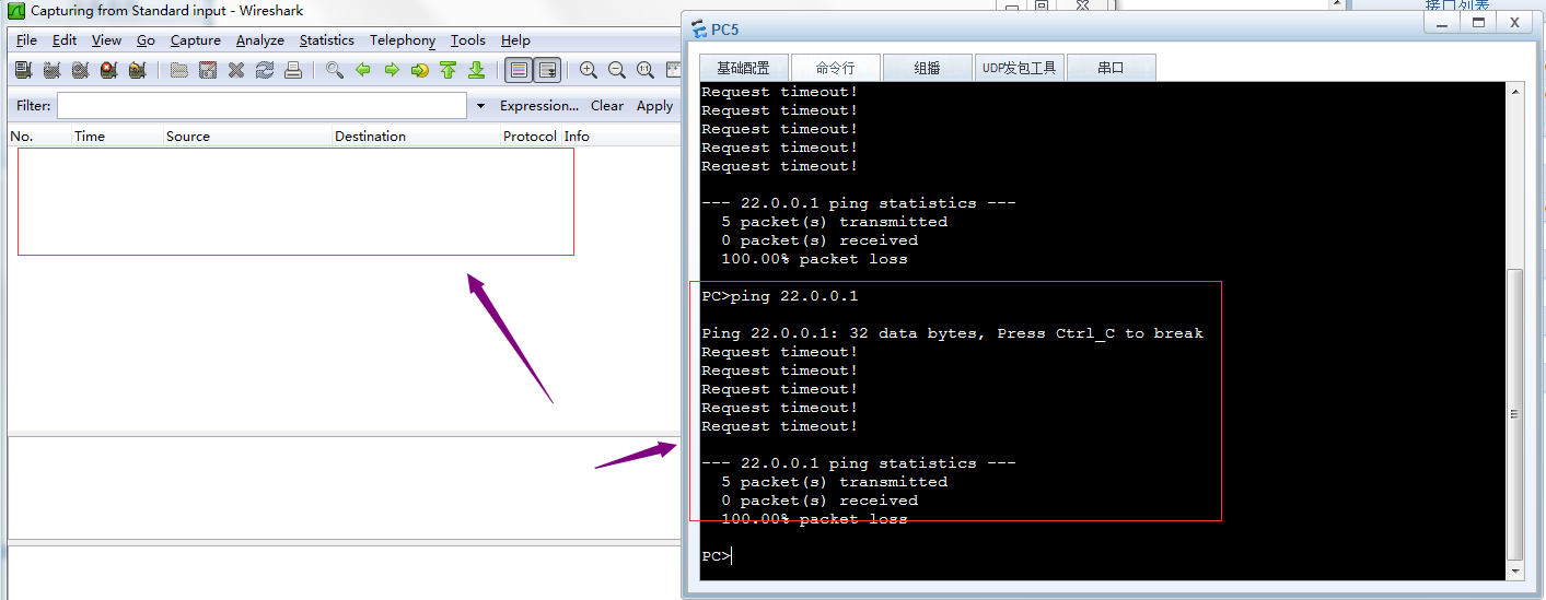
提示:可以看到在R1的g0/0/2口上没有抓到任何数据包,说明ping22.0.0.1的数据包没有在r1和r2直连链路上通过,所以我们ping pc6回馈给我们的是请求超时,其原因是R1上没有去往pc6的路由,当R1收到pc5发来的数据包,查看对应数据包是去往22.0.0.1的,R1在自己的路由表中没有匹配到去往22.0.0.1的路由,所以R1直接将对应数据包丢弃,不予转发;
验证:用pc5 ping pc7 看看是否能够正常通信?
PC>ipconfig

Link local IPv6 address...........: fe80::5689:98ff:fe54:5adc

IPv6 address......................: :: / 128

IPv6 gateway......................: ::

IPv4 address......................: 10.0.0.1

Subnet mask.......................: 255.255.255.0

Gateway...........................: 10.0.0.254

Physical address..................: 54-89-98-54-5A-DC

DNS server........................:

PC>ping 11.0.0.1

Ping 11.0.0.1: 32 data bytes, Press Ctrl_C to break

Request timeout!

From 11.0.0.1: bytes=32 seq=2 ttl=127 time=16 ms

From 11.0.0.1: bytes=32 seq=3 ttl=127 time=16 ms

From 11.0.0.1: bytes=32 seq=4 ttl=127 time=16 ms

From 11.0.0.1: bytes=32 seq=5 ttl=127 time<1 ms

--- 11.0.0.1 ping statistics ---

  5 packet(s) transmitted

  4 packet(s) received

  20.00% packet loss

  round-trip min/avg/max = 0/12/16 ms

PC>
提示:可以看到pc5 是可以正常和pc7通信;其实原因很简单,就是因为R1上有对应去往pc7和pc5的直连路由,所以pc5和pc7可以正常通信;通过上述实验,可以看到直连路由的优点是它自动生成,只要管理员正确配置了ip地址,并且在接口上接上了线,对应直连路由就会自动生成了;缺点就是不能和非直连的网络通信;这样一来我们要想和非直连网络通信,光凭直连路由是做不到;
静态路由
所谓静态路由就是指管理员人工手动添加的路由信息;
添加静态路由的命令语法
ip route-static 目标网络 子网掩码/前缀 下一跳地址/出接口
提示:如果出接口为以太网接口,则必须要指定下一跳地址,如果出接口为串口,可以使用下一跳或出接口来配置;
实验:还是上面的top,实现pc5能够ping 通pc6
在R1上添加静态路由
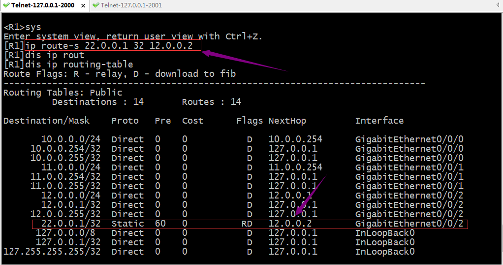
验证:现在R1上有去往pc6的路由信息,用pc 5ping pc6 看看是否可以正常通信?
PC>ipconfig

Link local IPv6 address...........: fe80::5689:98ff:fe54:5adc

IPv6 address......................: :: / 128

IPv6 gateway......................: ::

IPv4 address......................: 10.0.0.1

Subnet mask.......................: 255.255.255.0

Gateway...........................: 10.0.0.254

Physical address..................: 54-89-98-54-5A-DC

DNS server........................:

PC>ping 22.0.0.1

Ping 22.0.0.1: 32 data bytes, Press Ctrl_C to break

Request timeout!

Request timeout!

Request timeout!

Request timeout!

Request timeout!

--- 22.0.0.1 ping statistics ---

  5 packet(s) transmitted

  0 packet(s) received

  100.00% packet loss

PC>
提示:可以看到pc5现在依然ping 不通pc6;
在r1的g0/0/2口抓包,看看是否有对应数据包通过?
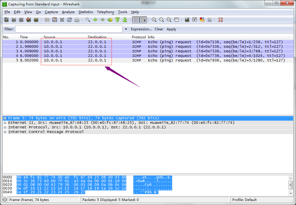
提示:现在在R1的g0/0/2口可以抓到pc5 ping pc 6的包,但是没有pc6 回来的包,其原因是R2上没有到达pc5所在网络的路由;所以pc5 ping 不同pc6;
在R2上添加去往pc5的路由
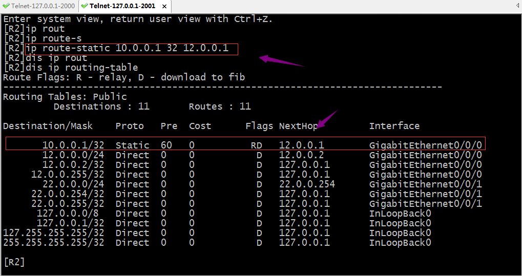
验证:现在用pc5再次ping pc6看看是否能通?
PC>ipconfig

Link local IPv6 address...........: fe80::5689:98ff:fe54:5adc

IPv6 address......................: :: / 128

IPv6 gateway......................: ::

IPv4 address......................: 10.0.0.1

Subnet mask.......................: 255.255.255.0

Gateway...........................: 10.0.0.254

Physical address..................: 54-89-98-54-5A-DC

DNS server........................:

PC>ping 22.0.0.1

Ping 22.0.0.1: 32 data bytes, Press Ctrl_C to break

Request timeout!

From 22.0.0.1: bytes=32 seq=2 ttl=126 time=16 ms

From 22.0.0.1: bytes=32 seq=3 ttl=126 time=16 ms

From 22.0.0.1: bytes=32 seq=4 ttl=126 time=16 ms

From 22.0.0.1: bytes=32 seq=5 ttl=126 time=16 ms

--- 22.0.0.1 ping statistics ---

  5 packet(s) transmitted

  4 packet(s) received

  20.00% packet loss

  round-trip min/avg/max = 0/16/16 ms

PC>
提示:可以看到pc5可以正常ping 通pc6了;
验证:在R1的g0/0/2口抓包,看看对应数据包是否有回复了?
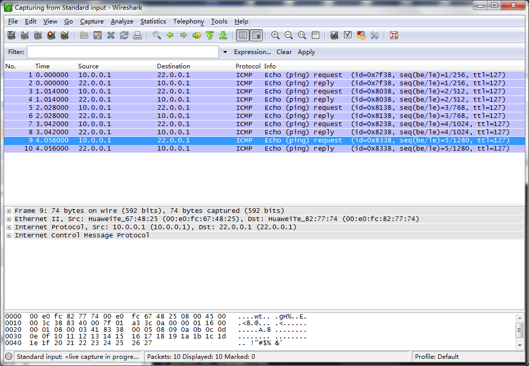
提示:可以看到现在在R1的g0/0/2口抓包就有正常回复包;
验证:pc7 ping pc6,看看是否能够ping通?
PC>ipconfig

Link local IPv6 address...........: fe80::5689:98ff:fe99:6332

IPv6 address......................: :: / 128

IPv6 gateway......................: ::

IPv4 address......................: 11.0.0.1

Subnet mask.......................: 255.255.255.0

Gateway...........................: 11.0.0.254

Physical address..................: 54-89-98-99-63-32

DNS server........................:

PC>ping 22.0.0.1

Ping 22.0.0.1: 32 data bytes, Press Ctrl_C to break

Request timeout!

Request timeout!

Request timeout!

Request timeout!

Request timeout!

--- 22.0.0.1 ping statistics ---

  5 packet(s) transmitted

  0 packet(s) received

  100.00% packet loss

PC>
提示:可以看到pc7到现在依然无法Ping通pc6,其原因是r2没有回来pc7的路由,所以pc7现在能够把包送达到pc6,但回不来,所以导致pc7ping不同pc6;要想实现pc7ping通pc6,我们还需要在r2上添加一条去往pc7的路由;
在R2上添加去往pc7的路由
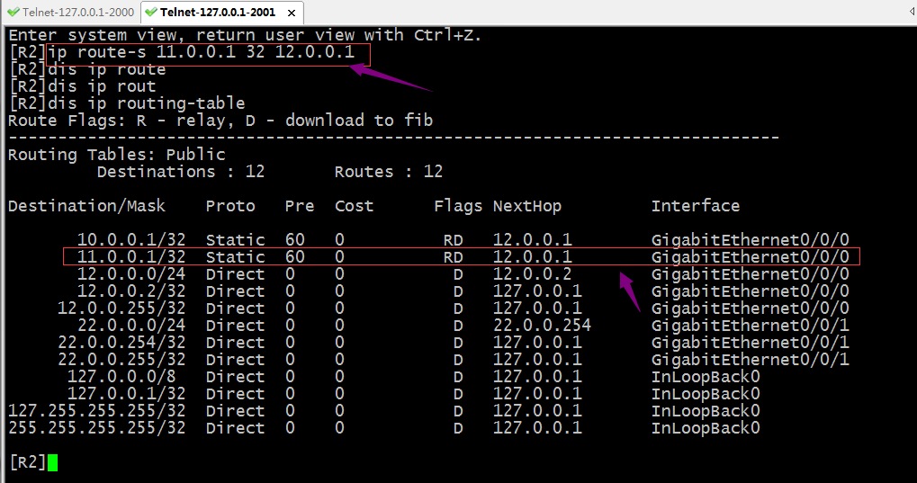
验证:现在pc7 ping pc6,看看是否可以正常通信?
PC>ipconfig

Link local IPv6 address...........: fe80::5689:98ff:fe99:6332

IPv6 address......................: :: / 128

IPv6 gateway......................: ::

IPv4 address......................: 11.0.0.1

Subnet mask.......................: 255.255.255.0

Gateway...........................: 11.0.0.254

Physical address..................: 54-89-98-99-63-32

DNS server........................:

PC>ping 22.0.0.1

Ping 22.0.0.1: 32 data bytes, Press Ctrl_C to break

From 22.0.0.1: bytes=32 seq=1 ttl=126 time=16 ms

From 22.0.0.1: bytes=32 seq=2 ttl=126 time=16 ms

From 22.0.0.1: bytes=32 seq=3 ttl=126 time=16 ms

From 22.0.0.1: bytes=32 seq=4 ttl=126 time=16 ms

From 22.0.0.1: bytes=32 seq=5 ttl=126 time=16 ms

--- 22.0.0.1 ping statistics ---

  5 packet(s) transmitted

  5 packet(s) received

  0.00% packet loss

  round-trip min/avg/max = 16/16/16 ms

PC>
提示:可以看到pc7现在也能正常ping通pc6;通过上述实验我们发现静态路由的配置还是很简单,必须手动指定目标网络,掩码以及下一跳;其次网络通信的过程是是双向的,配置静态路由,我们必须考虑来回的路由在所经过的路由器都要有对应的路由;如果网络规模非常大(网段特别多,路由器特别多),如果用手动配置静态路由的方式,就不是很容易了;所以静态路由适用于网络规模不是太大的环境中;除此之外静态路由有一个非常大的缺点,它不能根据top变化而变化,这样一来,如果现网中某个接口地址的发生变化,管理员必须手动更改路由信息;
负载分担
负载分担就是等价路由即到达同一目标网络的路由有多条,并且他们的优先级开销都一样;
实验:如下图,配置pc5和pc6通信的流量都可以走R1,R2之间的两条链路
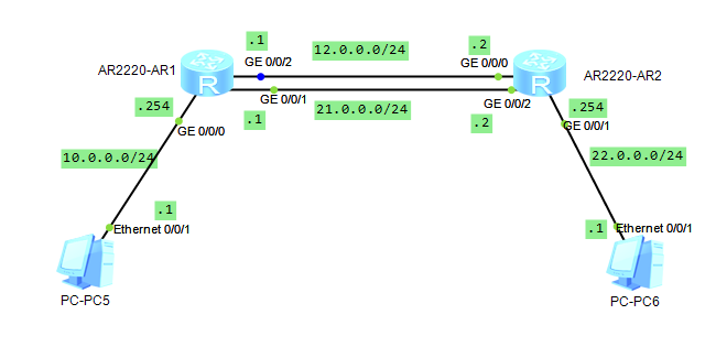
在R1的g0/0/1接口上配置对应的ip地址,并配置访问pc6的对应路由信息
<R1>sys

Enter system view, return user view with Ctrl+Z.

[R1]int g0/0/1

[R1-GigabitEthernet0/0/1]ip add 21.0.0.1 24

[R1-GigabitEthernet0/0/1]q

[R1]ip route-s 22.0.0.1 32 21.0.0.2

[R1]dis ip routin

[R1]dis ip routing-table

Route Flags: R - relay, D - download to fib

------------------------------------------------------------------------------

Routing Tables: Public

         Destinations : 14       Routes : 15

Destination/Mask    Proto   Pre  Cost      Flags NextHop         Interface

       10.0.0.0/24  Direct  0    0           D   10.0.0.254      GigabitEthernet0/0/0

     10.0.0.254/32  Direct  0    0           D   127.0.0.1       GigabitEthernet0/0/0

     10.0.0.255/32  Direct  0    0           D   127.0.0.1       GigabitEthernet0/0/0

       12.0.0.0/24  Direct  0    0           D   12.0.0.1        GigabitEthernet0/0/2

       12.0.0.1/32  Direct  0    0           D   127.0.0.1       GigabitEthernet0/0/2

     12.0.0.255/32  Direct  0    0           D   127.0.0.1       GigabitEthernet0/0/2

       21.0.0.0/24  Direct  0    0           D   21.0.0.1        GigabitEthernet0/0/1

       21.0.0.1/32  Direct  0    0           D   127.0.0.1       GigabitEthernet0/0/1

     21.0.0.255/32  Direct  0    0           D   127.0.0.1       GigabitEthernet0/0/1

       22.0.0.1/32  Static  60   0          RD   12.0.0.2        GigabitEthernet0/0/2

                    Static  60   0          RD   21.0.0.2        GigabitEthernet0/0/1

      127.0.0.0/8   Direct  0    0           D   127.0.0.1       InLoopBack0

      127.0.0.1/32  Direct  0    0           D   127.0.0.1       InLoopBack0

127.255.255.255/32  Direct  0    0           D   127.0.0.1       InLoopBack0

255.255.255.255/32  Direct  0    0           D   127.0.0.1       InLoopBack0

[R1]
在R2的g0/0/2接口上配置对应的ip地址,并配置访问pc5的对应路由信息
<R2>sys

Enter system view, return user view with Ctrl+Z.

[R2]int g0/0/2

[R2-GigabitEthernet0/0/2]ip add 21.0.0.2 24

Jul  3 2021 00:34:04-08:00 R2 %%01IFNET/4/LINK_STATE(l)[0]:The line protocol IP on the interface GigabitEthernet0/0/2 has entered the UP state.

[R2-GigabitEthernet0/0/2]q

[R2]ip route-s 10.0.0.1 32 21.0.0.1

[R2]dis ip routing

[R2]dis ip routing-table

Route Flags: R - relay, D - download to fib

------------------------------------------------------------------------------

Routing Tables: Public

         Destinations : 15       Routes : 16

Destination/Mask    Proto   Pre  Cost      Flags NextHop         Interface

       10.0.0.1/32  Static  60   0          RD   12.0.0.1        GigabitEthernet0/0/0

                    Static  60   0          RD   21.0.0.1        GigabitEthernet0/0/2

       11.0.0.1/32  Static  60   0          RD   12.0.0.1        GigabitEthernet0/0/0

       12.0.0.0/24  Direct  0    0           D   12.0.0.2        GigabitEthernet0/0/0

       12.0.0.2/32  Direct  0    0           D   127.0.0.1       GigabitEthernet0/0/0

     12.0.0.255/32  Direct  0    0           D   127.0.0.1       GigabitEthernet0/0/0

       21.0.0.0/24  Direct  0    0           D   21.0.0.2        GigabitEthernet0/0/2

       21.0.0.2/32  Direct  0    0           D   127.0.0.1       GigabitEthernet0/0/2

     21.0.0.255/32  Direct  0    0           D   127.0.0.1       GigabitEthernet0/0/2

       22.0.0.0/24  Direct  0    0           D   22.0.0.254      GigabitEthernet0/0/1

     22.0.0.254/32  Direct  0    0           D   127.0.0.1       GigabitEthernet0/0/1

     22.0.0.255/32  Direct  0    0           D   127.0.0.1       GigabitEthernet0/0/1

      127.0.0.0/8   Direct  0    0           D   127.0.0.1       InLoopBack0

      127.0.0.1/32  Direct  0    0           D   127.0.0.1       InLoopBack0

127.255.255.255/32  Direct  0    0           D   127.0.0.1       InLoopBack0

255.255.255.255/32  Direct  0    0           D   127.0.0.1       InLoopBack0

[R2]
提示:这样配置以后,pc5所在网络和pc6所在网络的设备通信就有两条链路一起负载,这样可以减少之前一条链路的压力;
验证:用tracert 追踪pc5和pc6通信所走的链路

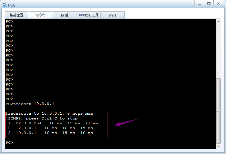
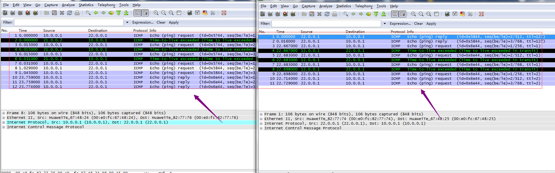
提示:从上面的链路追踪和抓包可以看到现在pc5和pc6通信,两条链路都用上了,pc5pingpc6走下面21网段,回复包全部走12网段所在链路,pc6pingpc5 去走12网段所在链路,回来走21网段所在链路;
浮动路由
浮动路由又称主备路由,即去往同一网络的多条路由中有主备之分,默认情况主路由工作(活动路由),一旦活动路由宕掉,备份路由马上就变为活动路由;一旦主路由恢复,备份路由又会处于非活动状态;有点类似keepalived的抢占模式,一旦主挂了,备份路由马上变为主,一旦原来的主活了,现在的主马上就变为备份路由;其原理就是在等价路由的基础上,借助路由器转发原则根据其优先级来确定那条路由存在路由表(最优路由),一旦存在路由表中的最优路由链路宕掉,对应接口也会随之宕掉,所以对应最优路由来说,其出接口就会变为unknow状态,导致路由不可用,此时根据路由转发原则,原来的次优路由就会变为最优路由,一旦优先级最小的路由所在链路恢复正常,路由器又会根据路由转发原则把次优路由替换下来,让其处于非活动状态;
实验:还是上述top,在R1上配置12网段所在链路为主链路,21网段为备份链路
配置r1
[R1]dis ip routing-table protocol static

Route Flags: R - relay, D - download to fib

------------------------------------------------------------------------------

Public routing table : Static

         Destinations : 1        Routes : 2        Configured Routes : 2

Static routing table status : <Active>

         Destinations : 1        Routes : 2

Destination/Mask    Proto   Pre  Cost      Flags NextHop         Interface

       22.0.0.1/32  Static  60   0          RD   12.0.0.2        GigabitEthernet0/0/2

                    Static  60   0          RD   21.0.0.2        GigabitEthernet0/0/1

Static routing table status : <Inactive>

         Destinations : 0        Routes : 0

[R1]ip rou

[R1]ip route-s 22.0.0.1 32 21.0.0.2 pre 61

Info: Succeeded in modifying route.

[R1]dis ip routing-table protocol static

Route Flags: R - relay, D - download to fib

------------------------------------------------------------------------------

Public routing table : Static

         Destinations : 1        Routes : 2        Configured Routes : 2

Static routing table status : <Active>

         Destinations : 1        Routes : 1

Destination/Mask    Proto   Pre  Cost      Flags NextHop         Interface

       22.0.0.1/32  Static  60   0          RD   12.0.0.2        GigabitEthernet0/0/2

Static routing table status : <Inactive>

         Destinations : 1        Routes : 1

Destination/Mask    Proto   Pre  Cost      Flags NextHop         Interface

       22.0.0.1/32  Static  61   0          R    21.0.0.2        GigabitEthernet0/0/1

[R1]
提示:在R1上修改原有去往22.0.0.1 下一跳为21.0.0.2 的路由的优先级为61,此时对应路由器来说,去往22.0.0.1的两条路由就不再是等价路由,所以下一跳为12.0.0.2的路由就会被选为最优路由,下一跳为21.0.0.2的路由就会被选为次优非活动路由;这里需要提醒的是以上路由只是针对r1,对r2来说,它的路由还是等价路由,并不会改变;
配置R2,12网段所在链路为备份链路,21网段为主链路
[R2]dis ip routing-table protocol static

Route Flags: R - relay, D - download to fib

------------------------------------------------------------------------------

Public routing table : Static

         Destinations : 2        Routes : 3        Configured Routes : 3

Static routing table status : <Active>

         Destinations : 2        Routes : 3

Destination/Mask    Proto   Pre  Cost      Flags NextHop         Interface

       10.0.0.1/32  Static  60   0          RD   12.0.0.1        GigabitEthernet0/0/0

                    Static  60   0          RD   21.0.0.1        GigabitEthernet0/0/2

       11.0.0.1/32  Static  60   0          RD   12.0.0.1        GigabitEthernet0/0/0

Static routing table status : <Inactive>

         Destinations : 0        Routes : 0

[R2]ip route-s 10.0.0.1 32 12.0.0.1 pre 61

Info: Succeeded in modifying route.

[R2]dis ip routing-table protocol static

Route Flags: R - relay, D - download to fib

------------------------------------------------------------------------------

Public routing table : Static

         Destinations : 2        Routes : 3        Configured Routes : 3

Static routing table status : <Active>

         Destinations : 2        Routes : 2

Destination/Mask    Proto   Pre  Cost      Flags NextHop         Interface

       10.0.0.1/32  Static  60   0          RD   21.0.0.1        GigabitEthernet0/0/2

       11.0.0.1/32  Static  60   0          RD   12.0.0.1        GigabitEthernet0/0/0

Static routing table status : <Inactive>

         Destinations : 1        Routes : 1

Destination/Mask    Proto   Pre  Cost      Flags NextHop         Interface

       10.0.0.1/32  Static  61   0          R    12.0.0.1        GigabitEthernet0/0/0

[R2]
验证:在R1上把12网段所在接口宕掉,看看对应的备份路由是否会成为活动路由?
<R1>sys

Enter system view, return user view with Ctrl+Z.

[R1]dis ip int b

*down: administratively down

^down: standby

(l): loopback

(s): spoofing

The number of interface that is UP in Physical is 4

The number of interface that is DOWN in Physical is 0

The number of interface that is UP in Protocol is 4

The number of interface that is DOWN in Protocol is 0

Interface                         IP Address/Mask      Physical   Protocol

GigabitEthernet0/0/0              10.0.0.254/24        up         up

GigabitEthernet0/0/1              21.0.0.1/24          up         up

GigabitEthernet0/0/2              12.0.0.1/24          up         up

NULL0                             unassigned           up         up(s)

[R1]int g0/0/2

[R1-GigabitEthernet0/0/2]shutdow

Jul  3 2021 01:22:12-08:00 R1 %%01IFPDT/4/IF_STATE(l)[0]:Interface GigabitEthernet0/0/2 has turned into DOWN state.

[R1-GigabitEthernet0/0/2]

[R1-GigabitEthernet0/0/2]

Jul  3 2021 01:22:13-08:00 R1 %%01IFNET/4/LINK_STATE(l)[1]:The line protocol IP on the interface GigabitEthernet0/0/2 has entered the DOWN state.

[R1-GigabitEthernet0/0/2]q

[R1]dis ip routing-table protocol static

Route Flags: R - relay, D - download to fib

------------------------------------------------------------------------------

Public routing table : Static

         Destinations : 1        Routes : 2        Configured Routes : 2

Static routing table status : <Active>

         Destinations : 1        Routes : 1

Destination/Mask    Proto   Pre  Cost      Flags NextHop         Interface

       22.0.0.1/32  Static  61   0          RD   21.0.0.2        GigabitEthernet0/0/1

Static routing table status : <Inactive>

         Destinations : 1        Routes : 1

Destination/Mask    Proto   Pre  Cost      Flags NextHop         Interface

       22.0.0.1/32  Static  60   0               12.0.0.2        Unknown

[R1]
提示:可以看到R1上的g0/0/2接口宕掉以后,对应活动路由变成了非活动路由,原来的非活动路由变成了活动路由;当然路由的变化也意味着其数据包的走向也发生了变化,从而实现链路切换;
恢复R1上的g0/0/2接口,看看对应路由变化
[R1-GigabitEthernet0/0/2]undo shutdown

[R1-GigabitEthernet0/0/2]

Jul  3 2021 01:26:52-08:00 R1 %%01IFPDT/4/IF_STATE(l)[2]:Interface GigabitEthernet0/0/2 has turned into UP state.

[R1-GigabitEthernet0/0/2]

Jul  3 2021 01:26:52-08:00 R1 %%01IFNET/4/LINK_STATE(l)[3]:The line protocol IP on the interface GigabitEthernet0/0/2 has entered the UP state.

[R1-GigabitEthernet0/0/2]q

[R1]dis ip routing-table protocol static

Route Flags: R - relay, D - download to fib

------------------------------------------------------------------------------

Public routing table : Static

         Destinations : 1        Routes : 2        Configured Routes : 2

Static routing table status : <Active>

         Destinations : 1        Routes : 1

Destination/Mask    Proto   Pre  Cost      Flags NextHop         Interface

       22.0.0.1/32  Static  60   0          RD   12.0.0.2        GigabitEthernet0/0/2

Static routing table status : <Inactive>

         Destinations : 1        Routes : 1

Destination/Mask    Proto   Pre  Cost      Flags NextHop         Interface

       22.0.0.1/32  Static  61   0          R    21.0.0.2        GigabitEthernet0/0/1

[R1]
提示:可以看到当接口恢复,对应活动路由又会变为非活动路由,实现了链路和路由的切换;当然对于r2也是同样的原理;从某种意义上我们可以理解浮动路由其实就是链接的高可用;
缺省路由
从上面的实验和配置过程来看,使用静态路由,必须在对应路由器上配置上数据包来回的路由,如果没有对应网段的路由,则我们就不能够正常访问对应的目标网络;这样一来我们如果要访问的网络非常多,比如互联网,我们不能也不应该把全互联网所有路由都写进路由器,即便可以,运营商和互联网的路由非常多,一般路由器也存不下,为了解决这样的问题,缺省路由就可以派上用场了;所谓缺省路由是指,在路由表中,所有未被匹配的路由,都可以被缺省路由所匹配;缺省路由以0.0.0.0为目标网络,掩码为0.0.0.0或前缀为0 来表示匹配任意目标网络;根据路由器的转发原则,掩码最长匹配优先,缺省路由的优先级是最低的,即最后才会被匹配;缺省路由的作用是减少路由条目,减轻路由器查找匹配路由的压力;通常用于末梢网络,比如家庭上网,企业出口;缺省路由可以静态配置,也可通过动态路由协议发布;
实验:静态配置缺省路由,实现pc5和pc6互通

配置R1
<Huawei>sys

Enter system view, return user view with Ctrl+Z.

[Huawei]sys R1

[R1]int g0/0/0

[R1-GigabitEthernet0/0/0]ip add 10.0.0.254 24

[R1-GigabitEthernet0/0/0]int g0/0/1

[R1-GigabitEthernet0/0/1]ip add 12.0.0.1 24

Jul  3 2021 01:55:33-08:00 R1 %%01IFNET/4/LINK_STATE(l)[0]:The line protocol IP on the interface GigabitEthernet0/0/0 has entered the UP state.

[R1-GigabitEthernet0/0/1]ip add 12.0.0.1 24

[R1-GigabitEthernet0/0/1]q

[R1]ip route-s 0.0.0.0 0 12.0.0.2

Jul  3 2021 01:55:33-08:00 R1 %%01IFNET/4/LINK_STATE(l)[1]:The line protocol IP on the interface GigabitEthernet0/0/1 has entered the UP state.

[R1]ip route-s 0.0.0.0 0 12.0.0.2

[R1]dis ip routing-table pro static

Route Flags: R - relay, D - download to fib

------------------------------------------------------------------------------

Public routing table : Static

         Destinations : 1        Routes : 1        Configured Routes : 1

Static routing table status : <Active>

         Destinations : 1        Routes : 1

Destination/Mask    Proto   Pre  Cost      Flags NextHop         Interface

        0.0.0.0/0   Static  60   0          RD   12.0.0.2        GigabitEthernet0/0/1

Static routing table status : <Inactive>

         Destinations : 0        Routes : 0

[R1]
配置R2
<Huawei>sys

Enter system view, return user view with Ctrl+Z.

[Huawei]sys R2

[R2]int g0/0/0

[R2-GigabitEthernet0/0/0]ip add 12.0.0.2 24

[R2-GigabitEthernet0/0/0]int g0/0/1

[R2-GigabitEthernet0/0/1]ip add 22.0.0.254

Jul  3 2021 01:55:45-08:00 R2 %%01IFNET/4/LINK_STATE(l)[0]:The line protocol IP on the interface GigabitEthernet0/0/0 has entered the UP state.

[R2-GigabitEthernet0/0/1]ip add 22.0.0.254 24

[R2-GigabitEthernet0/0/1]q

[R2]ip route-s 0.0.0.0 0 12.0.0.1

Jul  3 2021 01:55:45-08:00 R2 %%01IFNET/4/LINK_STATE(l)[1]:The line protocol IP on the interface GigabitEthernet0/0/1 has entered the UP state.

[R2]ip route-s 0.0.0.0 0 12.0.0.1

[R2]dis ip routing-table protocol static

Route Flags: R - relay, D - download to fib

------------------------------------------------------------------------------

Public routing table : Static

         Destinations : 1        Routes : 1        Configured Routes : 1

Static routing table status : <Active>

         Destinations : 1        Routes : 1

Destination/Mask    Proto   Pre  Cost      Flags NextHop         Interface

        0.0.0.0/0   Static  60   0          RD   12.0.0.1        GigabitEthernet0/0/0

Static routing table status : <Inactive>

         Destinations : 0        Routes : 0

[R2]
验证:用pc5 ping pc6 看看是否可以互通?

提示:可以看到配置缺省静态路由以后,pc5是可以正常和pc6通信;同样的原理,pc6也是可以正常和pc5通信;有了缺省路由我们只需要写一条了路由,即可匹配任意路由;这里需要提醒一下,缺省路由一般用于末梢网络,如果不是末梢网络的路由器,需要结合静态明细路由或动态路由;
HCNA Routing&Switching之静态路由的更多相关文章
- HCNA Routing&Switching之动态路由基本概念
前文我们了解了静态路由的相关话题,回顾请参考https://www.cnblogs.com/qiuhom-1874/p/14965433.html:今天我们来聊一聊动态路由相关概念: 首先我们要清楚什 ...
- HCNA Routing&Switching之路由基础
在开始聊路由之前,我们首先要明白在网络通讯里,什么是路由?什么是路由表.路由器以及网关的相关术语:路由简单讲就是指网络数据包从源头到目标的路径,主要用来为不同网络间通讯提供数据包转发依据:路由表就是多 ...
- HCNA Routing&Switching之动态路由协议RIP
前文我们了解了动态路由的基本概念,以及动态路由和静态路由的区别,优缺点,动态路由的分类,回顾请参考https://www.cnblogs.com/qiuhom-1874/p/14995317.html ...
- HCNA Routing&Switching之OSPF缺省路由发布
前文我们了解了OSPF的度量值,以及基础配置命令的总结,回顾请参考https://www.cnblogs.com/qiuhom-1874/p/15069632.html:今天我们来聊一聊在ospf里动 ...
- HCNA Routing&Switching之STP基础
前文我们了解了VLAN动态注册协议GVRP相关话题,回顾请参考https://www.cnblogs.com/qiuhom-1874/p/15113770.html:今天我们来讨论下二层环路和STP相 ...
- HCNA Routing&Switching之地址转换技术NAT
前文我们了解了包过滤工具ACL相关话题,回顾请参考https://www.cnblogs.com/qiuhom-1874/p/15156308.html:今天我们来聊一聊地址转换技术NAT相关话题: ...
- HCNA Routing&Switching之广域网协议HDLC和PPP
前文我们了解了地址转换技术NAT相关话题,回顾请参考https://www.cnblogs.com/qiuhom-1874/p/15168042.html:今天我们来聊一聊广域网中的两个二层封装协议H ...
- HCNP Routing&Switching之BGP路由宣告
前文我们了解了BGP报文结构.类型以及邻居状态相关话题,回顾请参考https://www.cnblogs.com/qiuhom-1874/p/15422924.html:今天我们来聊一聊BGP路由宣告 ...
- HCNA Routing&Switching之VLAN间路由
前文我们了解了二层交换技术vlan相关话题,回顾请参考https://www.cnblogs.com/qiuhom-1874/p/15091491.html:今天我们来聊一聊不同VLAN间通信相关话题 ...
随机推荐
- systemverilog动态数组
- fragment之间相互传数据、共享数据
在 Fragment 之间共享数据 Activity 中的两个或更多 Fragment 需要相互通信是一种很常见的现象.想象一下拆分视图 (master-detail) Fragment 的常见情况, ...
- Navicat Premium 15 linux 安装与激活 ArchLinux 2021
查看了很多教程花了半小时才弄好可真不容易 参考https://github.com/orginly/navicat-keygen 下载地址 http://www.navicat.com.cn/down ...
- camera数字降噪(DNR)
camera数字降噪(DNR) 闭路电视摄像机 无论多么出色和弱光,在黑暗中拍摄视频监控录像时都会不可避免地产生一些噪音.噪声是任何电子通信中不可避免的部分,无论是视频还是音频.本质上是静态的–视频信 ...
- 字符识别OCR原理及应用实现
字符识别OCR原理及应用实现 文本是人类最重要的信息来源之一,自然场景中充满了形形色色的文字符号.光学字符识别(OCR)相信大家都不陌生,就是指电子设备(例如扫描仪或数码相机)检查纸上打印的字符,通过 ...
- YOLOv4没交棒,但YOLOv5来了!
YOLOv4没交棒,但YOLOv5来了! 前言 4月24日,YOLOv4来了! 5月30日,"YOLOv5"来了! 这里的 "YOLOv5" 是带有引号的,因为 ...
- 激光雷达Lidar与毫米波雷达Radar:自动驾驶的利弊
激光雷达Lidar与毫米波雷达Radar:自动驾驶的利弊 Lidar vs Radar: pros and cons for autonomous driving 新型无人驾驶汽车的数量在缓慢增加,各 ...
- 分布式Jmeter压测机的部署
部署 1.分布式配置 Master机Jmeter安装目录下/bin/jmeter.properties remote_hosts修改为slave压力机的IP 如 remote_hosts=10.0.4 ...
- 移动通信-5G
1.移动通信的发展历程: "G"代表一代,每10年一个周期 1G 2G 3G 4G 5G 1980s 1990s 2000s 2010s 2020s 语音 短信 社交应用 在线.互 ...
- Rethinking Training from Scratch for Object Detection
Rethinking Training from Scratch for Object Detection 一. 概述 正常训练目标检测的流程分为以下几种: 在imagenet上进行预训练,然后在特定 ...