LabTool : LPC LINK2, LPC4370 cheap scope: 80Ms/s 12 bit
80MHz 12 bit ADC processor LPC4370.
LPCxpresso do a LPC LINK2 and LABTOOLS open source oscilloscope demo set. (£84 from Mouser, seems quite well liked.)
The LPC LINK2 is £14 + VAT from Mouser, it has the ADC on board. The Lab tools board has signal conditioning, BNC, protection etc.
Using just the LPCLINK2 board:
Remove C14. Add a 27K resistor between the old C14 input pin and pin 2 of J4 (VDDA +3.3V). Replace R3 with a range set resistor, for example 100k for about +-10V input. (gives 5mV resolution.) The open circuit input will float up slightly. The input impedance of the ADC is specified as 5k in parallel with 4.5pF. Bandwidth will be around 10MHz.
Connect input to J4 pin 6 and a GND to pin 1.
There are a number of possible variants which may perform better or be easier to do or provide additional channels.

The open source software would have to be hacked as various peripherals on the lab tools board are missing.
I have not tried this proposed mod.


Review
http://www.drdobbs.com/embedded-systems/embedded-tools/240168337
Datasheet
http://www.nxp.com/documents/data_sheet/LPC4370.pdf
http://www.lpcware.com/lpclink2
http://www.embeddedartists.com/products/app/labtool.php
Source firmware and app:
https://github.com/embeddedartists/labtool
Relevant links
https://groups.google.com/forum/#!topic/labtool/Rtp3ZCPygfU

It is an add-on board to LPC-Link 2 (which is based on the LPC4370 - a 204 MHz Cortex-M4 with an 80 MHz ADC and two extra Cortex-M0 cores).
LabTool make use of all features on the LPC4370, creating a powerful development tool.
- 11 channel logic analyzer (up to 100Msamples per second)
- 2 channel oscilloscope (up to 80 Msamples per second, 6MHz BW)
- 11 channel digital signal generator (up to 80 Msamples per second)
- 2 channel analog signal generator (40kHz BW)
The feature rich Windows software interface supports:
- One shot and continuous sampling
- Sorting and moving of signals
- SPI, I2C, UART signal interpreters
- Project settings can be saved and restored
- Collected data can be exported
- Four cursors available to help interpret captured data
- Open source software
- Prepared for running under Linux and MAC
LabTool
| Digital inputs | • 11 channel logic analyzer • without trigger: 100 Msps (1-4 ch), 50 Msps (5-8 ch), 20 Msps (9-11 ch) • with trigger: 100 Msps (1-2 ch), 80 Msps (3-4 ch), 40 Msps (5-8 ch), 20 Msps (9-11 ch) • Falling/rising edge triggers with logical OR between channels • 3.3V logic level as default but 2.4-5.5V supported via DIO_VCC |
| Analog inputs | • 2 channel oscilloscope • 60 Msps (1 ch) and 30 Msps (2 ch) sampling (can be increased to 80/40 Msps if no hardware trigger is enabled) • +-25V input range, 1 Mohm input impedance, TBD pF input capacitance • AC/DC control • BNC connector and flexible cables via 26-pos IDC connector • 6 MHz BW (3 MHz for 20mV/div range and up to 12 MHz on 0.2V/div and 5V/div range) |
| Digital outputs | • 11 channel digital signal generator • 80 Msps • 3.3V logic level |
| Analog outputs | • 2 channel analog signal generator • +-5V, 40 kHz BW • Sine, square and triangle waveforms |
| Dimensions | 83 x 90 mm |
| Power | 5.0V via mini-B USB connector |
| Connectors |
• 26-pos IDC connector for digial and analog I/O |
| Other | • 12 channel demo signal generator (UART, I2C, SPI, counter, PWM) from on-board LPC812. • HW provision for I2C logging (sw not implemented) • Analog calibration, can be done by user • Open source software |
Documents
- LabTool User's Manual
- Board Schematics (Login required)
- LPC4370 product page (the LPC4370 is a tripple core processor, 1xCM4+2xCM0, and have a fast ADC, 80Msample/sec)
- Embedded Artists' general RoHS 2 declaration
Installer
- For Windows: LabTool Installer v1.2 (27.5Mb) (MD5 checksum: f30c7bbe35f910c4909fe31b29e19298)
- For Raspberry Pi: labtool_raspi_2014-04-28.tgz (1Mb) (MD5 checksum: f205cf32c887665382f5299896d857e4)
Instructions for using the Raspberry Pi archive can be found here
- Binaries for the LPC4370 and LPC812: labtool_binaries_2014-04-28.zip (74Kb) (MD5 checksum: a4b93ea42e1e4efa360f3236b8294ba4)
Software
The software is open source and is available on github
Discussions
There is a mailing list available for discussions about problems or improvements.
Embedded Tools
The board provides logic analyzer, an oscilloscope, and a digital/analog signal generator.
I mentioned last time that programmers and electrical engineers have it rough because you can't really see what's going on in your design. That's probably why most of us love tools like oscilloscopes and logic analyzers.
Being a ham radio operator, I've had a scope since I was a kid. But buying a scope for personal use used to mean buying something old or something with very little capability, or both. Now you can get a scope that would have broke the bank a few years ago for about what a low-end PC would cost.
Still, even that's a bit much if you are just a casual user. There are a lot of inexpensive alternatives that connect to a PC or have a little screen but they aren't usually very good. They can still be better than nothing.
I did run into a sort of "in between" board the other day when I was writing about the LPC-Link debugger for the LPC-series ARM chips. I bought an LPC-Link 2 board for about $20 and then found that there was another product from Embedded Artists that included an LPC-Link 2 board. It was called LabTool.
It is a little hard to characterize exactly what it is. At the core, it is an ARM-based development board. The board contains an LPC4370, which is a 204 MHz Cortex M4 processor. There are also two extra Cortex M0 processors onboard and an 80MHz analog to digital converter. That's a lot of horsepower. The board mates with an LPC Link 2 board and you can detach the link board and use it for other things if you want.
Of course, that's only useful if you want to write some software. The selling point is the open source LabTool software that provides an 11-channel logic analyzer (up to 100 million samples per second), a 2-channel analog oscilloscope that can achieve up to 80 million samples per second, an 11-channel signal generator that can hit 80 million samples per second, and a 2-channel analog signal generate (up to 40 kHz). You can see an example run of the digital and analog sampling in the figure below.

ECG Application Example using LPC4370 and LabTool Hardware
ADCHS and DAC programming with LPC-Link 2 + LabTool
Dirceu Rodrigues, Jr. - Oct. 2013
Bio
Dirceu Rodrigues, Jr. is a computer engineer with a master's degree in electrical engineering. As an independent consultant, he tests new products with particular interest in the areas of wireless sensor networks, ARM processors, DSP, motor control, and medical applications.
Introduction
When I got involved with this campaign, my initial idea was to use the NXP LPC4370 microcontroller available on the LPC-Link 2 to implement a multicore FIR filter.Combined with the analog processing capabilities present on LabTool add-on board, would be ideal to put in place a structure which I discussed on ESC Brazil 2013 (MulticoreMicrocontrollers in Instrumentation and Control). But after a time studying the schematics of these boards, I realized that understanding the signal conditioning circuits, gain settings, input calibration and the correct use of ADCHS (12 bit High Speed ADC) peripheral and external DAC, deserve a whole article. For me, the most important feature of the board LPC-Link 2 (in addition to being a programmer/debugger for the target) is able to program a generic application on LPC4370 memory, since there are several analog/digital pins availableon expansion connectors.
Firstly, I downloaded the latest version of the ARM Keil µVision (V4.72.10.0). At time, I had not experienced the new LPCOpen library, so I changed the LPC43xx.h provided by the compiler to add a raw support for ADCHS peripheral - renaming it to LPC43xx_new.h. The change consists primarily in define register addresses, enabling references such as “LPC_ADCHS->xxx”. Before attach LPC-Link 2 on top of LabTool board, I connected the 10 pin SWD cable on J2 of LPC-Link 2, according Figure 1. Will look like the cable issqueezed between the boards, but that is quite normal. Also, the user must to ensure the other connectors are not slightly misaligned.

LabTool - Analog Inputs
Next I tried to unveil the structure around the high speed analog to digital converter. The reason for the presence of the BNC connectors on LabTool is to implement a complete two channel oscilloscope, whose features are far from modest, since the LPC4370 includes a 12 bit ADC, and can operate up to 80 MHz. Note that the two 10 bit ADC modules are absent on LPC4370 TFBGA100 package used in LabTool. A very simplified schematic of input conditioning circuit for each channel is shown on Figure 2. The complete design, provided by Embedded Artists[1], includes several other components, including capacitors for shaping the frequency response.

All settings are controlled via the SPI interface, including the DC/AC coupling. The input (0.5 V) is provided by a proper MCU pin related to ADCHS, as I will explainlater. Two analog multiplexers allow set the gain when changing the operational amplifier feedback resistor. From the nominal values of components on figure, we can write some equations for the DC model:

The LPC4370 ADC is a flash type with differential input - Figure 3.

The value converted to digital domain, as presented on page 1287 of LPC43xx User Manual (2013 draft version), is:

Through the DCINNEG and DCINPOS bits on ADCHS POWER_CONTROL register, the user can add a 0.5 V DC offset to the differential inputs. In the case of Labtool board, is convenient make DCINNEG = 1 and DCINPOS = 0, considering the presence of amp op with the non-inverting input voltage

according Figure 2. With these settings:

Also, note that

Substituting these results on Eq. 4:

and:

The value of GA depends on position of two multiplexers (feedback resistor selection 1 out 8)
and SPDT switch (divided input voltage selection VU or VD).
So, I can create the Table 1, which allow me to calculate the analog input value or VCH1, for each selection.

In order to obtain a value of acceptable precision it's required to compensate the ADC readings (NADC) for component tolerances and other deviations associated with the inputconditioning circuit. This is done in software. An affine function (gain and offset) makes the correction based on the current reading and previous calibration data – Listing 1.

Remember that a measuring instrument is not only as good as its components, but also as the calibration method used.
LabTool - Analog Outputs
The Digital to Analog section is more straightforward.
Since the 10 bit DAC module is absent on LPC4370 TFBGA100 package, the LabTool board relies
on external DAC102S085 from National to output two analog voltages.
As before, the simpler schematic on Figure 4 shows the essential components for the DC model.

On LabTool board, the LPC4370 SSP1 peripheral has three usages:
- Settings for the ADCHS conditioning circuit.
- Writing on DAC
- Communication with an EEPROM
The sharing is carried out through appropriate slave selection signals (SSEL and GPIOs) from MCU.
The DAC has two channels with internal data register including controls for update/refresh timing.

Application: Filtering an ECG
In order to test the ADCHS and related equations obtained from the LabTool manufacturer schematics, I decided to program the ARM Cortex-M4 on LPC4370 to implement a stop-band FIR (Finite Impulse Response) filter with 127 taps. The idea is to filter an ECG signal corrupted by 60 Hz hum. To avoid building a circuit around an instrumentation amplifier(something I've done a few times) and waste some skin electrodes; I thought using the computer sound card to generate the desired signal. So, the following tasks were performed:
- Find an ECG signal database in audio format [2].
- Select the file ecg.wav (60s duration, 16 bit, 1 kSa/s).
- Extract the file data on Matlab, insert a 60 Hz noise and rewrite it in wav format .
- Play the file on computer line-out using a software for audio editing like GoldWave.
This will allow some experimentation, as repeat intervals, invert polarity, attenuate and many other useful transformations - Figure 6.
- Design a notch FIR filter in Matlab and simulate the result.
- Make a header file with the generated 127 coefficients.

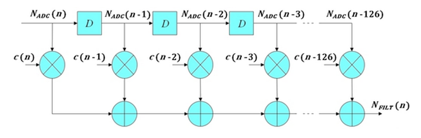
For this application, I used DC coupling on input (capacitor short-circuited on Figure 2). Also, the ADCHS was configured to present the result in two’s complement format (other option is offset binary) . Figure 7 shows a diagram for the FIR filter - coefficients and output labeled as c and NFILT, respectively.
To check the result, the filtered signal is sent to the analog output in real time. For this it’s necessary to perform a conversion between the ADCHS and DAC102S085 ranges using appropriate equations. Here I have at least two options:
1. Taking advantage of maximum available resolution (not used):
In this case, the conversion is performed through the Equation 10 and Figure 8.

2. Equal amplitudes (input/output):
In the ECG filtering applicatioon it is desirable that the original and filtered signals had the same amplitude, or a 1:1 relationship. Therefore, I've carried a different conversion in order to meet VEXT_AOUT1 = VCH1. Still maintaining the gain 10 between VCH1 and NFILT and equating Eq. 12 and Eq. 9:


The sampling and output rates both are equal to 1k/s. Note an approximate delay of 64 ms between input and output (representing taps/2 samples). This powerfulmicrocontroller and its high speed ADC are able to handle sample rates much higher than the one I used here, including multichannel audio. As I mentioned earlier,the purpose of this simple application is just to introduce the analog resources available on LabTool board.
Conclusion
The ADCHS has many other configuration options. It works through a state machine with a dedicated timer and a set of eight descriptors, for which it is possible to establish how andwhen a conversion occurs, generating interrupts, filling a 16 position FIFO or transferring data through DMA
The clock for this application was adjusted to 180 MHz, a value more than sufficient. In a next installment, I intend to wake-up the other two Cortex-M0 cores on the LPC4370, implementing a truly multicore filter through IPC (Inter-process Communication), running at a lower clock; something like 60 MHz and compare the results with the single core solution– for example, analyzing the power consumption. Stay tuned [3].
References
[1] http://www.embeddedartists.com
[2] http://courses.engr.illinois.edu/bioe415/labs/ecgwav.html
[3] http://www.youtube.com/DirceuRodriguesJr
LabTool : LPC LINK2, LPC4370 cheap scope: 80Ms/s 12 bit的更多相关文章
- LPC LINK2 IO CONNECTOR
- 081、Weave Scope 多主机监控(2019-04-29 周一)
参考https://www.cnblogs.com/CloudMan6/p/7674011.html Weave Scope 除了监控容器,还可以监控Docker Host. 点击顶部 HOS ...
- 第 10 章 容器监控 - 081 - Weave Scope 多主机监控
除了监控容器,Weave Scope 还可以监控 Docker Host 点击顶部 HOSTS 菜单项,地图将显示当前 host. 与容器类似,点击该 host 图标将显示详细信息 host 当前的资 ...
- java web学习总结(二十八) -------------------JSP中的JavaBean
一.什么是JavaBean JavaBean是一个遵循特定写法的Java类,它通常具有如下特点: 这个Java类必须具有一个无参的构造函数 属性必须私有化. 私有化的属性必须通过public类型的方法 ...
- ng-option指令使用记录,设置默认值需要注意
ng-options一般有以下用法: 数组作为数据源: label for value in array select as label for value in array label group ...
- Spring Boot 乐观锁加锁失败 - 集成AOP
Spring Boot with AOP 手头上的项目使用了Spring Boot, 在高并发的情况下,经常出现乐观锁加锁失败的情况(OptimisticLockingFailureException ...
- Siteserver-stl:searchOutput(搜索结果)自定义显示样式
stl:searchOutput 自定义显示样式 自定义搜索提交表单需要在<stl:searchOutput>中嵌入显示搜索结果的标签,必须包含的标签 有<stl:pageConte ...
- 转载:[AngularJS系列] 那伤不起的provider们啊~ (Provider, Value, Constant, Service, Factory, Decorator)
来源:http://hellobug.github.io/blog/angularjs-providers/ 用AngularJS做项目,但凡用过什么service啊,factory啊,provide ...
- javaweb学习总结(二十)——JavaBean总结
一.什么是JavaBean JavaBean是一个遵循特定写法的Java类,它通常具有如下特点: 这个Java类必须具有一个无参的构造函数 属性必须私有化. 私有化的属性必须通过public类型的方法 ...
随机推荐
- Jmeter如何保持cookie,让所有请求都能用同一个cookie,免去提取JSESSIONID
近期有柠檬班的学生找到华华,问了一个问题,就是利用Jmeter做接口测试的时候,如何提取头部的JSESSIONID然后传递到下一个请求,继续完成当前用户的请求. 其实,关于这个问题有三种种解决方法: ...
- 各浏览器 position: fixed 造成的bug 通用解决办法,Safari, iOS
将原来使用 position: fixed 的元素外层包裹一个 div.fixedWrapper .fixedWrapper { width: 100%; overflow: hidden; pos ...
- Spring4总结
1. 明确Spring的主要作用就是为代码“解耦”,降低代码间的耦合度.使用IoC使得主业务在相互调用过程中,不用再自己维护关系了,即不用再自己创建要使用的对象了,而是由Spring容器统一管理,自动 ...
- pytorch函数之torch.normal()
Returns a Tensor of random numbers drawn from separate normal distributions who’s mean and standard ...
- 升级openssh到最新版本
首先,下载最新版本,传到服务器:http://mirror.aarnet.edu.au/pub/OpenBSD/OpenSSH/portable/ 安装 cd /root/ mkdir ssh_upg ...
- Linux内核源码分析--内核启动之(4)Image内核启动(setup_arch函数)(Linux-3.0 ARMv7)【转】
原文地址:Linux内核源码分析--内核启动之(4)Image内核启动(setup_arch函数)(Linux-3.0 ARMv7) 作者:tekkamanninja 转自:http://blog.c ...
- C# UDP广播消息
首先是发送端: /// <summary> /// 发送UDP消息 /// </summary> /// <param name="msg">消 ...
- 从零开始自己搭建复杂网络(以Tensorflow为例)
从零开始自己搭建复杂网络(以MobileNetV2为例) tensorflow经过这几年的发展,已经成长为最大的神经网络框架.而mobileNetV2在经过Xception的实践与深度可分离卷积的应用 ...
- zoj 3809 枚举水题 (2014牡丹江网赛 A题)
题目大意:给出一列取样的几个山的高度点,求山峰有几个? Sample Input 291 3 2 4 6 3 2 3 151 2 3 4 5Sample Output 30 # include < ...
- AIM Tech Round 4 (Div. 1) C - Upgrading Tree 构造 + 树的重心
C - Upgrading Tree 我发现我构造题好弱啊啊啊. 很明显能想到先找到重心, 然后我们的目标就是把所有点接到重心的儿子上,让重心的儿子子树变成菊花图, 这个先把重心到儿子的边连到 i , ...