Making my own Autonomous Robot in ROS / Gazebo, Day 1: Building the static model
Day 1: Building the static model
Source
Sources for this tutorial can be found on GitHub
Setting up
- ROS: Indigo
- OS: Ubuntu 14.04
- OS: Gazebo 7.0.0
Initialize the workspace
To create the basic skeleton of the directory structure, we begin with a workspace {WORKSPACE}_ws, where we set {WORKSPACE}=mybot.
cd ~

mkdir -p mybot_ws/src

cd mybot_ws/src

catkin_init_workspace

cd ..

catkin_make

echo "source ~/mybot_ws/devel/setup.bash" >> ~/.bashrc # Adds workspace to search path
In the src folder are three main packages, {MODEL}_control, {MODEL}_description, {MODEL}_gazebo. We set {MODEL} = mybot. To create a package: catkin_create_pkg {PKG_NAME} {PKG_DEPENDENCIES}. In this case, we have no {PKG_DEPENDENCIES} = “”.
cd ~/mybot_ws/src/

catkin_create_pkg mybot_control

catkin_create_pkg mybot_description

catkin_create_pkg mybot_gazebo
Creating your own World
Let’s start with the gazebo package, go in there and create the following subfolders:
roscd mybot_gazebo

mkdir launch worlds
At first we want to create a world for our gazebo server. Therefore we switch to our worlds directory and create a new world file.
cd worlds

gedit mybot.world
A basic world file defines at least a name:
<?xml version="1.0"?>

<sdf version="1.4">

<world name="myworld">

</world>

</sdf>
Here you could directly add models and object with their position. Also the laws of physics may be defined in a world. This is an important step to understand, because in this file you could also attach a specific plugin to an object. The plugin itself contains ROS and Gazebo specific code for more complex behaviors.
At first we just want to add some basic objects, like a ground and a basic illumination source inside the world tag.
    <include>

        <uri>model://sun</uri>

    </include>

    <include>

        <uri>model://ground_plane</uri>

    </include>
Check your “~/.gazebo/models” directory, as this is a default path for saved models. If this path does not exist try to find /usr/share/gazebo/setup.sh where gazebo looks for models. Otherwise add it to your model path.
As the ground plane and the sun are basic models that are also on the gazebo server they will be downloaded on startup if they cannot be found locally. If you want to know which object are available on the gazebo server, take a look at Gazebo model database. To start the gazebo server there are several methods. As it is a good practice to use a launch file, we will create one now. This could later also be used for multiple nodes.
Change to the launch directory of your project:
roscd mybot_gazebo/launch
Create a new file:
gedit mybot_world.launch
and insert:
<launch>

    <include file="$(find gazebo_ros)/launch/empty_world.launch">

        <arg name="world_name" value="$(find mybot_gazebo)/worlds/mybot.world"/>

        <arg name="gui" value="true"/>

    </include>

</launch>
This launch file will just execute a default launch file provided by Gazebo, and tell it to load our world file and show the Gazebo client. You can launch it by doing:
roslaunch mybot_gazebo mybot_world.launch
Now you should see the gazebo server and the gui starting with a world that contains a ground plane and a sun (which is not obviously visible without objects). If not, it can be that there are some connections problems with the server.
If that happens, start gazebo without the launch file, go to the models, you should find the one you want in the server. Click on them, they will be put in the cache. Now, if you close gazebo and start it again with the launch file, it should work.
If you would press “Save world as” in “File” in your gazebo client and save the world in a text file, you could investigate the full world description.
If you want to watch a more complex and beautiful world environment then add the following inside your world tag:
    <include>

        <uri>model://willowgarage</uri>

    </include>
This one shows you the office of Willow Garage, be careful, it’s huge and may make your simulation extremely slow.
Create the Robot Model (URDF)
In ~/mybot_ws/src/mybot_description/urdf, there will be four files:
- mybot.xacro: primary file that loads the other three files and contains only URDF items like joints and links
- mybot.gazebo: contains gazebo-specific labels that are wrapped within gaz
- materials.xacro: maps strings to colors
- macros.xacro: macros to help simplify
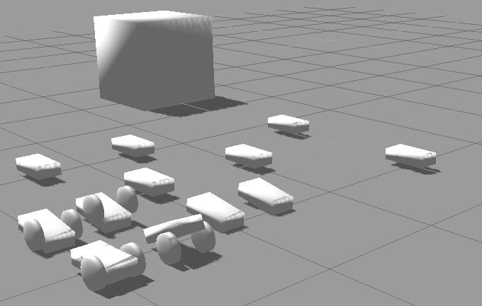
The more accurate you want to model your robot the more time you need to spend on the design. In the next image you see a developing process of a robot model, from a simple cube to a differential drive robot. You can also check the ROS tutorial about the robot.
We could put our model as a SDF file in the ~/.gazebo/models directory, this is the standard way when you work only with Gazebo. However with ROS we’ll prefer to use a URDF file generated by Xacro and put it the description package.
The Universal Robotic Description Format (URDF) is an XML file format used in ROS as the native format to describe all elements of a robot. Xacro (XML Macros) is an XML macro language. It is very useful to make shorter and clearer robot descriptions.
Ok so first we need to go into our description package and create the urdf subfolder and the description file:
roscd mybot_description

mkdir urdf

cd urdf

gedit mybot.xacro
XACRO CONCEPTS
- xacro:include: Import the content from other file. We can divide the content in different xacros and merge them using xacro:include.
- property: Useful to define constant values. Use it later using
${property_name} - xacro:macro: Macro with variable values. Later, we can use this macro from another xacro file, and we specify the required value for the variables. To use a macro, you have to include the file where the macro is, and call it using the macro’s name and filling the required values.
This file will be the main description of our robot. Let’s put some basic structure:
<?xml version="1.0"?>

<robot name="mybot" xmlns:xacro="http://www.ros.org/wiki/xacro">

        <!-- Put here the robot description -->

</robot>
The structure is basic for a urdf file. The complete description (links, joints, transmission…) have to be within the robot tag. The xmlns:xacro="http://www.ros.org/wiki/xacro" specifies that this file will use xacro. If you want to use xacro you have to put this.
With xacro, you can define parameters. Once again, this make the file clearer. They are usually put at the beginning of the file (within the robot tag, of course).
Let’s define some physical properties for our robot, mainly the dimensions of the chassis, the caster wheel, the wheels and the camera:
<xacro:property name="PI" value="3.1415926535897931"/>

<xacro:property name="chassisHeight" value="0.1"/>

<xacro:property name="chassisLength" value="0.4"/>

<xacro:property name="chassisWidth" value="0.2"/>

<xacro:property name="chassisMass" value=""/>

<xacro:property name="casterRadius" value="0.05"/>

<xacro:property name="casterMass" value=""/>

<xacro:property name="wheelWidth" value="0.05"/>

<xacro:property name="wheelRadius" value="0.1"/>

<xacro:property name="wheelPos" value="0.2"/>

<xacro:property name="wheelMass" value=""/>

<xacro:property name="cameraSize" value="0.05"/>

<xacro:property name="cameraMass" value="0.1"/>
‹arg name="gui" value="true"/›These parameters or properties can be used in all the file with ${property name}.
We will also include three files :
 <xacro:include filename="$(find mybot_description)/urdf/mybot.gazebo" />

 <xacro:include filename="$(find mybot_description)/urdf/materials.xacro" />

 <xacro:include filename="$(find mybot_description)/urdf/macros.xacro" />
These three correspond respectively to:
- all the gazebo-specific aspects of our robot
- definition of the materials used (mostly colors)
- definitions of some macros for easier description of the robot
Every file has to contain the robot tag and everything we put in them should be in this tag.
Now we want to add a rectangular base for our robot. Insert this within the robot tag of mybot.xacro:
<link name='chassis'>

  <collision>

    <origin xyz="0 0 ${wheelRadius}" rpy="0 0 0"/>

    <geometry>

      <box size="${chassisLength} ${chassisWidth} ${chassisHeight}"/>

    </geometry>

  </collision>

  <visual>

    <origin xyz="0 0 ${wheelRadius}" rpy="0 0 0"/>

    <geometry>

      <box size="${chassisLength} ${chassisWidth} ${chassisHeight}"/>

    </geometry>

    <material name="orange"/>

  </visual>

  <inertial>

    <origin xyz="0 0 ${wheelRadius}" rpy="0 0 0"/>

    <mass value="${chassisMass}"/>

    <box_inertia m="${chassisMass}" x="${chassisLength}" y="${chassisWidth}" z="${chassisHeight}"/>

  </inertial>

</link>
We define a box with chassisLength x chassisWidth x chassisHeight meters and mass chassisMasskg.
As you can see, we have three tags for this one box, where one is used to the collision detection engine, one to the visual rendering engine and the last to the physic engine. Most of the time they are the same, except when you have complicated and beautiful visual meshes.
As they don’t need to be that complicated for collision detection you could use a simple model for the collision. The material element in the visual tag refer to a color that must be defined in the materials.xacro and refred to in the mybot.gazebo file, at least, in the structure we adopted.
Add this in “mybot.gazebo”, within the robot tag :
<gazebo reference="chassis">

  <material>Gazebo/Orange</material>

</gazebo>
And this in the “materials.xacro” :
<material name="black">

  <color rgba="0.0 0.0 0.0 1.0"/>

</material>

<material name="blue">

  <color rgba="0.0 0.0 0.8 1.0"/>

</material>

<material name="green">

  <color rgba="0.0 0.8 0.0 1.0"/>

</material>

<material name="grey">

  <color rgba="0.2 0.2 0.2 1.0"/>

</material>

<material name="orange">

  <color rgba="${255/255} ${108/255} ${10/255} 1.0"/>

</material>

<material name="brown">

  <color rgba="${222/255} ${207/255} ${195/255} 1.0"/>

</material>

<material name="red">

  <color rgba="0.8 0.0 0.0 1.0"/>

</material>

<material name="white">

  <color rgba="1.0 1.0 1.0 1.0"/>

</material>
As you can see, we add more than just the color we wanted, this is for convenience. Now, we can leave this file alone and use any color we want.
Another particular thing in the chassis link is the use of “box_inertia” in the inertial tag. This is a macro made with xacro. As you can see, when you use a macro, you can simply use the tag and specifies the parameters. Xacro will understand.
Add this in the macros.xacro file, within the robot tag :
<macro name="cylinder_inertia" params="m r h">

  <inertia  ixx="${m*(3*r*r+h*h)/12}" ixy = "" ixz = ""

    iyy="${m*(3*r*r+h*h)/12}" iyz = ""

    izz="${m*r*r/2}"

  />

</macro>

<macro name="box_inertia" params="m x y z">

  <inertia  ixx="${m*(y*y+z*z)/12}" ixy = "" ixz = ""

    iyy="${m*(x*x+z*z)/12}" iyz = ""

    izz="${m*(x*x+z*z)/12}"

  />

</macro>

<macro name="sphere_inertia" params="m r">

  <inertia  ixx="${2*m*r*r/5}" ixy = "" ixz = ""

    iyy="${2*m*r*r/5}" iyz = ""

    izz="${2*m*r*r/5}"

  />

</macro>
Once again, we add more than we needed. We will use the others later. The inertia tag is a convention of the inertial tag in a link.
We have two small things to do before testing our model with gazebo.
The physic engine does not accept a base_link with inertia. It is then useful to add a simple link without inertia and make a joint between it and the chassis. Add this before the chassis link in the mybot.xacro file :
<link name="footprint" />

<joint name="base_joint" type="fixed">

  <parent link="footprint"/>

  <child link="chassis"/>

</joint>
In order to start gazebo with our model, we have to modify the previously created launch file mybot_world.launch by adding the following two tags in the launch tag:
<!-- urdf xml robot description loaded on the Parameter Server, converting the xacro into a proper urdf file-->

<param name="robot_description" command="$(find xacro)/xacro.py '$(find mybot_description)/urdf/mybot.xacro'" />

<!-- push robot_description to factory and spawn robot in gazebo -->

<node name="mybot_spawn" pkg="gazebo_ros" type="spawn_model" output="screen"

 args="-urdf -param robot_description -model mybot" />
The first tag will first call the xacro script to convert of xacro description into an actual URDF. This URDF is then inserted into a ROS parameter called “robot_description” (this is a standard name used by many ROS tools).
The second tag launches a program from the gazebo_ros package that will load the URDF from the parameter “robot_description” and spawn the model into our Gazebo simulator
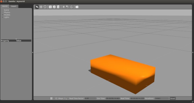
If you launch your project with this launch file, the gazebo client opens and the the chassis should be there. It should also fall because of the physic engine.
As a next step we add a caster wheel to the robot. This is the simplest wheel as we have no axis and no friction. We can simply approximate the caster wheel with a ball. Add this after the chassis link in the main urdf file :
<joint name="fixed" type="fixed">

  <parent link="chassis"/>

  <child link="caster_wheel"/>

</joint>

<link name="caster_wheel">

  <collision>

    <origin xyz="${casterRadius-chassisLength/2} 0 ${casterRadius-chassisHeight+wheelRadius}" rpy="0 0 0"/>

    <geometry>

      <sphere radius="${casterRadius}"/>

    </geometry>

  </collision>

  <visual>

    <origin xyz="${casterRadius-chassisLength/2} 0 ${casterRadius-chassisHeight+wheelRadius}" rpy="0 0 0"/>

    <geometry>

      <sphere radius="${casterRadius}"/>

    </geometry>

    <material name="red"/>

  </visual>

  <inertial>

    <origin xyz="${casterRadius-chassisLength/2} 0 ${casterRadius-chassisHeight+wheelRadius}" rpy="0 0 0"/>

    <mass value="${casterMass}"/>

    <sphere_inertia m="${casterMass}" r="${casterRadius}"/>

  </inertial>

</link>
We attach this caster wheel to the chassis with a fixed joint. The two links will then always move together. We use the sphere_inertia macro we added earlier in the macros.xacro file. Also add a gazebo tag in the gazebo file for this link :
<gazebo reference="caster_wheel">

  <mu1>0.0</mu1>

  <mu2>0.0</mu2>

  <material>Gazebo/Red</material>

</gazebo>
As usual, we specify the color used in material. We also added mu1 and mu2, with value 0 to remove the friction.
Last but not least, we want to add some wheels to the robot. We could add the two links in the main file, but let’s make one macro to make it simple. In the macro file, add this :
<macro name="wheel" params="lr tY">

<link name="${lr}_wheel">

  <collision>

    <origin xyz="0 0 0" rpy="0 ${PI/2} ${PI/2}" />

    <geometry>

      <cylinder length="${wheelWidth}" radius="${wheelRadius}"/>

    </geometry>

  </collision>

  <visual>

    <origin xyz="0 0 0" rpy="0 ${PI/2} ${PI/2}" />

    <geometry>

      <cylinder length="${wheelWidth}" radius="${wheelRadius}"/>

    </geometry>

    <material name="black"/>

  </visual>

  <inertial>

    <origin xyz="0 0 0" rpy="0 ${PI/2} ${PI/2}" />

    <mass value="${wheelMass}"/>

    <cylinder_inertia m="${wheelMass}" r="${wheelRadius}" h="${wheelWidth}"/>

  </inertial>

</link>

<gazebo reference="${lr}_wheel">

  <mu1 value="1.0"/>

  <mu2 value="1.0"/>

  <kp  value="10000000.0" />

  <kd  value="1.0" />

  <fdir1 value="1 0 0"/>

  <material>Gazebo/Black</material>

</gazebo>

<joint name="${lr}_wheel_hinge" type="continuous">

  <parent link="chassis"/>

  <child link="${lr}_wheel"/>

<origin xyz="${-wheelPos+chassisLength/2} ${tY*wheelWidth/2+tY*chassisWidth/2} ${wheelRadius}" rpy="0 0 0" />

  <axis xyz="0 1 0" rpy="0 0 0" />

  <limit effort="" velocity=""/>

  <joint_properties damping="0.0" friction="0.0"/>

</joint>

<transmission name="${lr}_trans">

  <type>transmission_interface/SimpleTransmission</type>

  <joint name="${lr}_wheel_hinge"/>

  <actuator name="${lr}Motor">

    <hardwareInterface>EffortJointInterface</hardwareInterface>

    <mechanicalReduction></mechanicalReduction>

  </actuator>

</transmission>

</macro>
The parameters allows us to specify which wheel we are talking about. “lr” could have two values (left or right) and “tY”, for translation along the Y-axis, also (respectively 1 and -1). There is nothing new concerning the link part.
The gazebo tag is inserted here so that we don’t need to worry about it every time we add a wheel. This macro is thus self-sufficient. The joint type is continuous. This allows a rotation around one axis. This axis is y 0 1 0 and connects each wheel to the chassis of your robot.
What’s new is the transmission element. To use ros_control with your robot, you need to add some additional elements to your URDF. The element is used to link actuators to joints, see the spec for exact XML format. We’ll use them in a minute.
Now you can add the wheels to the main file :
<wheel lr="left" tY=""/>

<wheel lr="right" tY="-1"/>
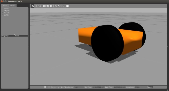
As you see, the macro makes it very simple.
Now you can launch your simulation and the full robot should appear!
Run the Models
Load the Gazebo simulator in a terminal
roslaunch mybot_gazebo mybot_world.launch
Version Control (recommended)
Initialize a new repo in github server, like making_my_robot_in_gazebo.
Save everythin in this new repo and set a new branch called "day1_static_model" by
git push --set-upstream origin day1_static_model
Reference
Making my own Autonomous Robot in ROS / Gazebo, Day 1: Building the static model的更多相关文章
- Making my own Autonomous Robot in ROS / Gazebo, Day 2: Enable the robot
Day 2: Enable the robot Git Setting git checkout master git branch day2_enable_robot git push --set- ...
- Gazebo Ros入门
教程代码 First step with gazebo and ros • setup a ROS workspace • create projects for your simulated rob ...
- Gazebo機器人仿真學習探索筆記(七)连接ROS
中文稍后补充,先上官方原版教程.ROS Kinetic 搭配 Gazebo 7 附件----官方教程 Tutorial: ROS integration overview As of Gazebo 1 ...
- ROS常用三維機器人仿真工具Gazebo教程匯總
參考網址: 1. http://gazebosim.org/tutorials 2. http://gazebosim.org/tutorials/browse Gazebo Tutorials Ga ...
- Robot Operating System (ROS)学习笔记2---使用smartcar进行仿真
搭建环境:XMWare Ubuntu14.04 ROS(indigo) 转载自古月居 转载连接:http://www.guyuehome.com/248 一.模型完善 文件夹urdf下,创建ga ...
- Gazebo與ROS版本說明
使用哪种ROS / Gazebo版本的组合 介绍 本文档提供了有关将不同版本的ROS与不同版本的Gazebo结合使用的选项的概述.建议在安装Gazebo ROS包装之前阅读它.重要!简单的分析,快速和 ...
- 在ROS Kinetic和Gazebo 8中使用智能汽车仿真演示
在ROS Kinetic和Gazebo 8中使用智能汽车仿真演示 智能车无人驾驶技术是目前人工智能和机器人技术的研究热点,有许多开源平台可以使我们零基础零成本入门无人驾驶技术.本文分享一下目前ROS官 ...
- getting started with building a ROS simulation platform for Deep Reinforcement Learning
Apparently, this ongoing work is to make a preparation for futural research on Deep Reinforcement Le ...
- ROS机器人程序设计(原书第2版)补充资料 (捌) 第八章 导航功能包集入门 navigation
ROS机器人程序设计(原书第2版)补充资料 (捌) 第八章 导航功能包集入门 navigation 书中,大部分出现hydro的地方,直接替换为indigo或jade或kinetic,即可在对应版本中 ...
随机推荐
- iptables参数详解
iptables参数详解 搬运工:尹正杰 注:此片文章来源于linux社区. Iptalbes 是用来设置.维护和检查Linux内核的IP包过滤规则的. 可以定义不同的表,每个表都包含几个内部的链,也 ...
- FTP服务器的安装和配置
FTP服务器的安装和配置 作者:尹正杰 版权声明:原创作品,谢绝转载!否则将追究法律责任. 本来是想出一个源码安装ftp的教程,但是想想还是算了,如果你自学python有个10天的话你自己就能写一个f ...
- 不同数据库中同一张表的SQL循环修改语句
select sample_value,Sample_GUID,row_number() over(order by sample_value )as rownumber into #AATemp ...
- csuoj 1116: Kingdoms
http://acm.csu.edu.cn/OnlineJudge/problem.php?id=1116 1116: Kingdoms Time Limit: 3 Sec Memory Limit ...
- 完美解决 nginx No input file specified.
一次开发中遇到了这个问题:No input file specified nginx版本1.8 找遍网络都是说 fastcgi_param SCRIPT_FILENAME $document_root ...
- redis 五种数据类型的使用场景
String 1.String 常用命令: 除了get.set.incr.decr mget等操作外,Redis还提供了下面一些操作: 获取字符串长度 往字符串append内容 设置和获取字符串的某一 ...
- Linux Crontab 安装使用详细说明
crontab命 令常见于Unix和Linux的操作系统之中,用于设置周期性被执行的指令.该命令从标准输入设备读取指令,并将其存放于“crontab”文件中,以供 之后读取和执行.通常,crontab ...
- ffmpeg将图片合成视频
本来想做个android录制屏幕的功能,但是目前只能是截图 然后把图片合成视频,这里就需要用到 ffmpeg 在做之前也是参考了其它一些比较不错的文章 比如:http://www.open-open. ...
- 夺命雷公狗-----React---16--事件操作事件
<!DOCTYPE> <html> <head> <meta charset="utf-8"> <title></ ...
- 【原创】我所理解的自动更新-外网web服务器配置
ClientDownload和ClientUpdate共享渠道配置信息: channel-0.php //以appstore的渠道为例 <?php define('APPNAME', 'TOKE ...