
The Secret Mixed-Signal Life of PWM Peripherals
The Secret Mixed-Signal Life of PWM Peripherals
Pulse-width modulation (PWM) peripherals have enjoyed a long association with microcontrollers and power control, starting with motor control and power conversion. For the most part, these applications use traditional digital PWM designs, with the PWM peripheral driving a MOSFET driver, which drives the MOSFET — which, in turn, drives the motor/inductor. The basic design elements of a counter, two digital-magnitude comparators and a flip flop stereotypically have been digital, placing the PWM peripheral in the same category as universal asynchronous receiver/transmitters (USARTs), serial peripheral interface (SPI) ports and general-purpose digital I/O.
Recently, however, some analog has slipped into the mix, which has changed the PWM peripheral from an upstanding member of the purely digital community into a mixed-signal module that seemingly has a secret double life — showing a digital face to the microcontroller, while secretly handling analog functions when the other digital peripherals aren't looking.
This all started innocently enough with the inclusion of a simple shutdown function driven by a voltage comparator. Initially, this change was intended to merely add an emergency overcurrent shutdown, only to be used in the direst of overcurrent conditions. However, once included in the design, the change slowly morphed the peripheral into a true mixed-signal, cycle-by-cycle current-limiting PWM module. Once this change occurred, the former purely digital PWM peripheral became the mixed-signal peripheral that we know today.
So, what types of mixed-signal designs led to this change? Quite a surprising number of them, actually, with power conversion being the initial step. Let's review this design.
A true “Level 4” switch-mode power supply (SMPS) involves full digital feedback and a PWM that outputs voltage with an analog-to-digital converter (ADC), filters the resulting values through a proportional integral differentiator (PID) software routine and then outputs the result to a standard all-digital PWM peripheral. The result is a fully digital version of a standard voltage-mode switching power supply. Fig. 1 shows a representative block diagram.

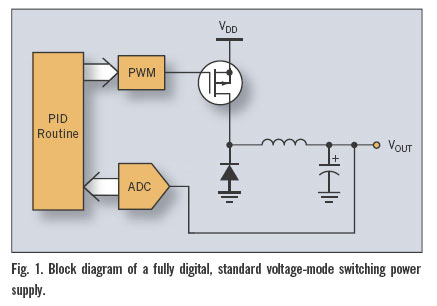
Although the advantages of a fully digital feedback path are impressive — including elimination of temperature and component-tolerance problems in the error-amplifier/loop filter, and the ability to switch the response characteristics on the fly — limitations still exist to this design. These limitations are primarily in the pulse-frequency restrictions imposed by the purely digital PWM. (Remember that a PWM peripheral with a resolution of 8 bits running at 500 kHz requires a 128-MHz clock.)
In fact, improving the PWM peripheral's resolution/frequency is one of the main drivers behind the introduction of PWM modules clocked by high-frequency, phase-locked loops. Further complicating the problem is the need for high resolution over a fairly restricted duty-cycle range. Unfortunately, this doesn't translate into a simpler circuit — it just adds the requirement for higher resolution over the PWM's entire duty-cycle range. The result is a predictably higher current draw and a correspondingly higher cost for the microcontroller.
Although higher clock frequencies are the purely digital solution, a mixed-signal design based upon the voltage-comparator shutdown solution has become popular for cost-sensitive applications. Using the combination of the PWM peripheral and a comparator-based shutdown, a cycle-by-cycle current limiting system is possible. This enables a current-mode design that does not require either a high-frequency clock or greater PWM resolution. A lower resolution PWM module can provide the maximum duty cycle required, while the comparator terminates the PWM pulse asynchronously in response to the inductor current feedback. The set point for the comparator could be generated by either an analog-loop filter or by a moderate resolution digital-to-analog converter (DAC) and the PID algorithm, described above. Fig. 2 illustrates the digital form of the resulting topology.


This step into mixed-signal design established the PWM peripheral as a mixed-signal device. Since then, designers have quickly jumped on the bandwagon, wondering if there are other mixed-signal jobs the PWM peripheral can perform. The answer is, of course, a resounding “yes.”
By combining a purely digital PWM with a low-pass filter, a low-frequency DAC can be created. The variable duty cycle of the digital PWM output is averaged by the low-pass filter to produce a variable voltage that is a percentage of the digital supply voltage, with the duty cycle of the PWM setting the percentage. The challenge is to set the RC filter corner frequency such that it adequately filters the ripple from the resulting output. Fig. 3 shows an example circuit.

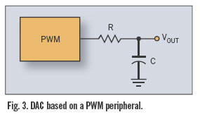
To keep the output ripple at less than one-half LSB of the PWM, the corner frequency for the filter must be greater than 1/Nth of the PWM frequency; where N is the maximum count of the PWM. For example, to adequately filter a 10-bit PWM, the filter must attenuate the 0 VDD swing of the PWM output down to less than 1/1,024th of VDD. Given that a single-pole RC attenuates a signal 10-to-1 for every decade of frequency; this means that the PWM pulse frequency must be 1,024 × the filter's corner frequency. Thus, a 10-kHz, 10-bit PWM needs a 10-Hz filter.
Of course, going to more poles in the filter will raise the corner frequency 10-to-1 per pole, per decode of frequency, moving the minimum corner frequency for the filter appropriately upward.
While this sounds simple, remember it has a couple of limitations. First, the lower the filter's corner frequency, the slower the slew rate of the DAC. Secondly, the more poles in the filter, the greater the leakage due to the capacitors and the more the offset in the output. Typically, the practical limit is two to three poles, generating a 100-to-1 to 1000-to-1 attenuation per decade in frequency. That gives a 10-bit PWM-based DAC with a 10-kHz pulse rate, and a 2-pole filter a maximum output slew rate of 1 mS to 2 mS for a 0 VDD shift.
Obviously, the PWM peripheral's mixed-signal life does not end here — countless variations have followed, including a PWM-driven attenuator. For this circuit, the PWM drives a simple RC filter as before, but a second input is introduced for the signal to be attenuated. Fig. 4 is an example circuit.


The PWM pulse shorts the incoming signal to ground during the active portion of each pulse, and then releases the incoming signal to pass unattenuated during the inactive portion. The resulting chopped waveform is then filtered by the RC network to remove the PWM switching frequency. The output is an attenuated version of the input, in which the attenuation was set by the PWM peripheral's duty cycle.
The challenge in the circuit design is to choose an appropriate corner frequency for the RC filter and a sufficiently high frequency for the PWM. The RC filter's corner frequency must be high enough to allow the incoming signal to pass without attenuation, or a significant phase shift at 0% attenuation. The corner frequency must also be low enough to sufficiently attenuate the PWM signal, chopping the signal. To meet both requirements, the incoming signal usually can be limited to only very low frequencies — typically, less than 100 Hz to 200 Hz. Also, keep in mind that a significant number of the incoming signal's harmonics must pass the filter as well, if the signal is to retain its original waveform.
Another factor influencing the design is that the filter's corner frequency, from the input point of view, is based on R1 plus R2; the corner frequency for the PWM is based upon R2 alone. However, as mentioned previously, going to a higher-order filter increases the PWM signal's attenuation, which allows a higher corner frequency while still attenuating the PWM chop.
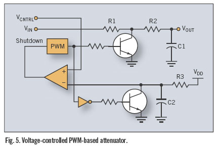
Another interesting circuit proposal is to combine the PWM peripheral's comparator-driven auto shutdown with the attenuator circuit discussed earlier. Remember that part of the reason for a transition to current mode in the switching power supply example is to allow an increase in resolution without increasing the PWM's clock frequency. The proposal is to apply a similar idea to the attenuator's frequency problem.
By adding a second open-collector output to the existing attenuator PWM and using it to short an RC network, a synchronized ramping voltage (similar to the ramping current in the current-mode switcher) can be created. The ramping voltage then is fed into the voltage comparator, with a control voltage driving the other comparator input. The result is a voltage-controlled PWM output. Given that the duty cycle of the PWM also determines the attenuation of the circuit, the final result is a voltage-controlled attenuator with the ability to use a higher PWM frequency without losing resolution.Fig. 5 is the example circuit.

So, the PWM peripheral has begun participating in circuits for driving MOSFETs, creating DACs and attenuating ac waveforms. Does this really constitute a complete fall from digital grace? If this were the extent of the PWM module's cross into the gray area of mixed-signal design, it could probably be forgiven and pulled back into the digital fold. However, once the PWM took its first steps into the seductive, low-cost nature of mixed-signal designs, other steps followed. Since then, the PWM peripheral has been firmly painted as a mixed-signal peripheral. Because of this, new fringe power-supply designs have come along.
For example, a hot-wire anemometer design is based on the principal that any object warmer than the ambient temperature will lose heat to any airflow. More importantly, the object will lose heat at a rate proportional to the airflow. If we build a circuit that heats an object to a few degrees warmer than the ambient air and then measure the heat loss, we can determine the airflow over the object. If the feedback circuit is designed such that the object in the airflow is always heated to just above ambient, then the ongoing energy requirement to keep it heated is equal to the heat loss to the airflow and proportional to the airflow itself.
To build this circuit, a few simple building blocks are needed: two temperature sensors (one for ambient and one for the heated object), a difference amplifier with an offset, a heater driven by the output of the amplifier and an integrator to sum the energy dumped into the heater. For the sake of simplicity, assume the heater is the warm object in the airflow.
The temperature sensors are easy — just a few positive temperature coefficient thermistors. The amplifier is simply an op-amp configured as a difference amplifier, and the driver for the heater is a PWM peripheral with the comparator shutdown feature. Together, they create a circuit that keeps the heated thermistor slightly warmer than the unheated thermistor (Fig. 6).

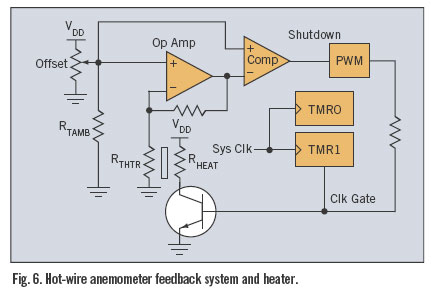
The system for accumulating the amount of energy dumped into the heater is just a counter with its clock gated by the PWM output. When the PWM output is high (heating the sensor), the counter increments. When the PWM output is low, the counter stops. A fixed sample period for the accumulation results in a counter value that is a percentage of full power to the heater. Scaled, with a subtraction of any fixed offsets, the value represents the airflow value in whatever units are needed.
Although the accumulation function of the counter is purely digital, the feedback and control of the PWM/comparator combination forever branded the PWM a mixed-signal peripheral. No longer a member of the purely black-and-white world of digital peripherals, today's PWM walks both sides of the line. It operates interchangeably as either purely digital control of an analog function or with analog feedback that places it into the mixed-signal camp. Whatever the future holds, for now the PWM peripheral's movement in the mixed-signal arena has given embedded designers another tool for monitoring and controlling our world.
The Secret Mixed-Signal Life of PWM Peripherals的更多相关文章
- Buck converter uses low-side PWM IC
The most common switching-power topology is a buck converter, which efficiently transforms high volt ...
- FCLK PCLK HCLK
一.对clock的基本认识 1 s3c2410的clock & power management模块包含三个部分:clock control.usb control.power control ...
- 这十大MCU厂商瓜分着中国市场
MCU(Micro Control Unit)中文名称为微控制单元,又称单片微型计算机(Single Chip Microcomputer)或者单片机,是指随着大规模集成电路的出现及其发展,将计算机的 ...
- Digital Current-Mode Control Challenges Analog Counterparts
http://electronicdesign.com/digital-ics/digital-current-mode-control-challenges-analog-counterparts ...
- 采用TL026等构成的宽带ALC放大器电路图
Building a Differential Amplifier An op-amp with no feedback is already a differential amplifier, am ...
- labview图形和图表的类型
http://zone.ni.com/reference/zhs-XX/help/371361L-0118/lvconcepts/types_of_graphs_and_charts/ LabVIEW ...
- DSP开发资源总结,经典书籍,论坛
OMAP4开发资源总结: 一.TI OMAP4官网介绍: http://www.ti.com.cn/general/cn/docs/wtbu/wtbuproductcontent.tsp?templa ...
- LSD-FET430UIF与MSP-FET430UIF
成功的破解了没人研究的东西很有成就感!世界需要这样的人!!!LSD-FET430UIF与MSP-FET430UIF?什么是MSPF149?网上查了很多这方面的资料,都没有,最后凭借我阅读PDF的精神和 ...
- TI公司与MSP430单片机
美国德州仪器(Texas Instruments)公司,简称TI,是全球领先的半导体公司,成立于1930 年,成立之初是一家使用地震信号处理技术勘探原油的地质勘探公司,1951年更名为德州仪器公司,1 ...
随机推荐
- Json学习整理
1:javascript对JSON的支持 2:java对JSON的支持 alibaba->fastjson 封装工具类: import com.alibaba.fastjson.JSONObje ...
- css3图片旋转
<!DOCTYPE html> <html lang="en"> <head> <meta http-equiv="Conten ...
- Coursera台大机器学习技法课程笔记07-Blending and Bagging
这一节讲如何将得到的feature或hypothesis组合起来用于预测. 1. 林老师给出了几种方法 在选择g时,需要选择一个很强的g来确保Eval最小,但如果每个g都很弱该怎么办呢 这个时候可以选 ...
- cf1104d二分+数学
#include<bits/stdc++.h> using namespace std; bool ask(int x,int y){ printf("? %d %d\n&quo ...
- 字节、字、bit、byte的关系【转】
字 word 字节 byte 位 bit 字长是指字的长度 1字=2字节(1 word = 2 byte) 1字节=8位(1 byte = 8bit) 一个字的字长为16 一个字节的字长是8 bps ...
- bootstrap改变上传文件按钮样式,并显示已上传文件名
参考博文: html中,文件上传时使用的<input type="file">的样式自定义 html中<input type="file"&g ...
- 你需要知道的 .NET
1. 简述private.protected.public.internal 修饰符的访问权限. 答. private : 私有成员, 在类的内部才可以访问. protected : 保护成员,该类内 ...
- visual studio 2015百度云下载
visual studio 2015百度云下载 https://pan.baidu.com/s/1b198Zo3mX5_zA2VX3xRRfw 提取码: 关注公众号[GitHubCN]回复2015获取
- mac和Linux的环境变量设置
摘抄自:http://hi.baidu.com/machao_pe/item/763d0ef12d32cd35fe3582db redhat和ubuntu中修改环境变量 2010-03-06 23:4 ...
- 013 JstlView
一:InternalResourceViewResolver 1.InternalResourceViewResolver JSP是常见的视图技术,可以使用InternalResourceViewRe ...