STM32 Hardware Development
http://www.st.com/web/en/resource/technical/document/application_note/CD00164185.pdf AN2586
The device requires a 2.0 V to 3.6 V operating voltage supply (VDD).
An embedded regulator is used to supply the internal 1.8 V digital power.
The real-time clock (RTC) and backup registers can be powered from the VBAT voltage
when the main VDD supply is powered off.
VDDA and VSSA must be connected to VDD and VSS, respectively

Independent A/D converter supply and reference voltage
To improve conversion accuracy, the ADC has an independent power supply that can be
filtered separately, and shielded from noise on the PCB.
● the ADC voltage supply input is available on a separate VDDA pin
● an isolated supply ground connection is provided on the VSSA pin
When available (depending on package), VREF– must be tied to VSSA.
On 100-pin and 144-pin packages
To ensure a better accuracy on low-voltage inputs, the user can connect a separate external
reference voltage ADC input on VREF+. The voltage on VREF+ may range from 2.4 V to VDDA.
On packages with 64 pins or less
The VREF+ and VREF- pins are not available, they are internally connected
to the ADC voltage supply (VDDA) and ground (VSSA).
Battery backup
To retain the content of the Backup registers when VDD is turned off, the VBAT pin can be
connected to an optional standby voltage supplied by a battery or another source.
The VBAT pin also powers the RTC unit, allowing the RTC to operate even when the main
digital supply (VDD) is turned off. The switch to the VBAT supply is controlled by the power
down reset (PDR) circuitry embedded in the Reset block.
If no external battery is used in the application, it is highly recommended to connect VBAT
externally to VDD.
Power supply schemes
The circuit is powered by a stabilized power supply, VDD.
● Caution:
– If the ADC is used, the VDD range is limited to 2.4 V to 3.6 V
– If the ADC is not used, the VDD range is 2.0 V to 3.6 V
● The VDD pins must be connected to VDD with external decoupling capacitors
(one 100 nF Ceramic capacitor for each VDD pin + one Tantalum or Ceramic capacitor
(min. 4.7 µF typ.10 µF).
● The VBAT pin can be connected to the external battery (1.8 V < VBAT < 3.6 V).
If no external battery is used, it is recommended to connect this pin to VDD
with a 100 nF external ceramic decoupling capacitor.
● The VDDA pin must be connected to two external decoupling capacitors
(100 nF Ceramic + 1 µF Tantalum or Ceramic).
● The VREF+ pin can be connected to the VDDA external power supply.
If a separate, external reference voltage is applied on VREF+,
a 100 nF and a 1 µF capacitors must be connected on this pin.
In all cases, VREF+ must be kept between 2.4 V and VDDA.
● Additional precautions can be taken to filter analog noise:
– VDDA can be connected to VDD through a ferrite bead.
– The VREF+ pin can be connected to VDDA through a resistor (typ. 47 Ω).

The STM32F1xx does not require an external reset circuit to power-up correctly.
Only a pulldown capacitor is recommended to improve EMS performance by protecting the device against parasitic resets.
Charging and discharging a pull-down capacitor through an internal resistor increases the device power consumption.
The capacitor recommended value (100 nF) can be reduced to 10 nF to limit this power consumption;

Clocks
Three different clock sources can be used to drive the system clock (SYSCLK):
● HSI oscillator clock (high-speed internal clock signal)
● HSE oscillator clock (high-speed external clock signal)
● PLL clock
The devices have two secondary clock sources:
● 40 kHz low-speed internal RC (LSI RC) that drives the independent watchdog and,
optionally, the RTC used for Auto-wakeup from the Stop/Standby modes.
● 32.768 kHz low-speed external crystal (LSE crystal) that optionally drives the real-time clock (RTCCLK)
Each clock source can be switched on or off independently when it is not used, to optimize the power consumption.


Boot mode selection

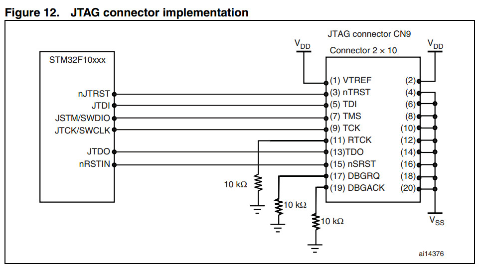
Debug management


STM32 Hardware Development的更多相关文章
- Calculate CRC32 as in STM32 hardware (EWARM v.5.50 and later)
http://supp.iar.com/Support/?note=64424&from=note+11927 BackgroundThe STM32 devices from ST Micr ...
- Linux下STM32开发环境的搭建
目录 一.概述 1.目的 2.开发环境描述 3.Eclipse构建的STM32集成开发环境结构 4.GDB / GDB Server 调试模型 二.搭建步骤 三.详细的搭建过程 1.安装eclipse ...
- STM32 USB FS Core and USB OTG Core
STM32 USB-FS-Device development kit Compatible with the STM32F102xx and STM32F103xx series, STM32 L1 ...
- IAR EWARM Checksum Technical Note
IELFTOOL Checksum - Basic actions EW targets: ARM, RH850, RX, SH, STM8 EW component: General issues ...
- ON THE EVOLUTION OF MACHINE LEARNING: FROM LINEAR MODELS TO NEURAL NETWORKS
ON THE EVOLUTION OF MACHINE LEARNING: FROM LINEAR MODELS TO NEURAL NETWORKS We recently interviewed ...
- wdk1703+vs2015编译的诡异问题
最近将wdk升级到1703(10.0.15063.0)版本,编译一个新建的minifiter项目居然出现了失败 提示错误为 WindowsDriver.common.targets(460,5): e ...
- stm32-arduino-f103
希望给工作中偶尔要用的一些辅助板卡(例如运行信息现场记录)找一个快速开发的手段,Arduino作为流行的开源嵌入硬件框架,组件丰富,资料众多,所以想以Arduino作为平台.但是Arduino板子基本 ...
- 微软职位内部推荐-Sr. SW Engineer for Privacy Id
微软近期Open的职位: Job posting title: Senior Software Engineer for Privacy Identification Profession: Engi ...
- AN2820 Driving bipolar stepper motors using a medium-density STM32F103xx microcontroller
AN2820 Driving bipolar stepper motors using a medium-density STM32F103xx microcontroller Introductio ...
随机推荐
- No manual entry for pthread_mutex_init .
$manpthread_mutex_init No manual entryfor pthread_mutex_init 解决方案: $sudo apt-get install manpages-po ...
- Linux系统调优及安全设置
1.关闭SELinux #临时关闭 setenforce 0 #永久关闭 vim /etc/selinux/config SELINUX=disabled 2.设定运行级别为3 #设定运行级别 vim ...
- 大型网站的 HTTPS 实践(一)—— HTTPS 协议和原理(转)
原文链接:http://op.baidu.com/2015/04/https-s01a01/ 1 前言 百度已经于近日上线了全站 HTTPS 的安全搜索,默认会将 HTTP 请求跳转成 HTTPS.本 ...
- Python编程规范精简版
用四个空格缩进,不要用tab键:四个空格是在较小缩进(可以允许更大的嵌套深度)和较大缩进(可读性更好)之间的一个很好的折中.制表符会带来混乱,最好不要使用: 包装行保证每行不超过79个字符:这对那些使 ...
- setitimer()
setitimer()为Linux的API,并非C语言的Standard Library,setitimer()有两个功能,一是指定一段时间后,才执行某个function,二是每间格一段时间就执行某个 ...
- Effective C++笔记(六):继承与面向对象设计
参考:http://www.cnblogs.com/ronny/p/3756494.html 条款32:确定你的public继承塑模出is-a关系 “public继承”意味着is-a.适用于base ...
- Effective C++笔记(三):资源管理
参考:http://www.cnblogs.com/ronny/p/3745098.html 资源:动态分配的内存.文件描述器.互斥锁.图形界面中的字型与笔刷.数据库连接以及网络sockets等, ...
- vmware linux虚拟机连接ip设置
首先: 点击VMware 编辑->虚拟网络编辑器: 然后选中VMnet8的查看NAT设置: 上图第二步(记下红框中网关地址和子网掩码): 第三步(用于设置虚拟机地址范围): 接下来就是设置虚拟机 ...
- DB2和Oracle中Date比较
- 三十三 StringIO和BytesIO
StringIO 很多时候,数据读写不一定是文件,也可以在内存中读写. StringIO顾名思义就是在内存中读写str. 要把str写入StringIO,我们需要先创建一个StringIO,然后,像文 ...