DSP28335的上手试用LED灯闪烁-第一篇
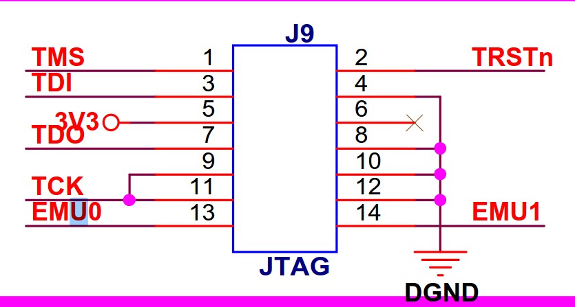
1. 本次以三兄弟的DSP28335开发板为例,看下JTAG接口,EMU0,EMU1的用途,不是很懂,不深入研究,用到再说
EMU0/1是TI芯片的JTAG才有的信号,本身不属于JTAG标准里的信号,有两个作用。
(1)设定芯片是仿真模式(上拉)还是边界扫描模式(下拉)。
(2)用做高速实时数据交换RTDX及TRACE等功能时。这个一般用户可能用不到。
所以这两个信号是双向的,这个信号一般来说不需加要buffer,直接连起来就好了,不用管他是单向还是双向。
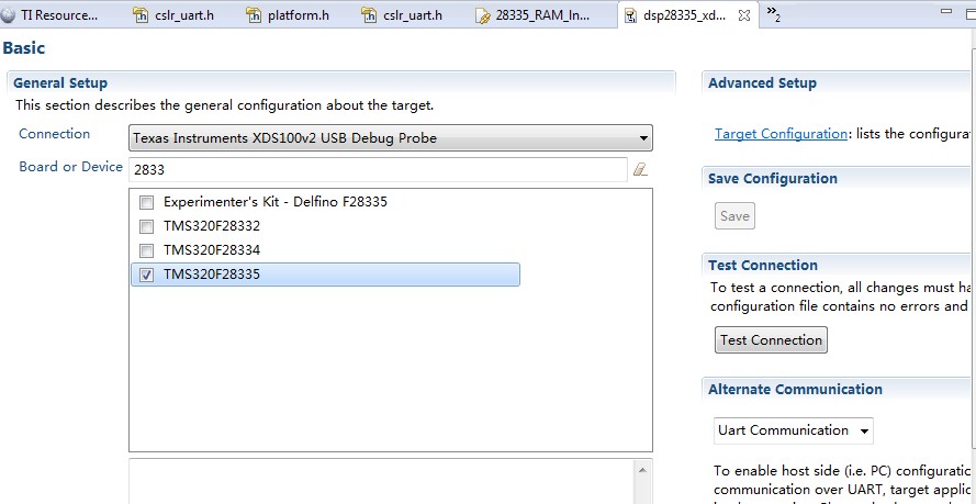
2. 打开工程,E:\dsp\SXD_C28335\SXD28335_PRO_1_V2\Example_2833x_LEDBlink,建立一个CCXML文件,编译一下工程
3. 看下引脚原理图,28335有3组GPIO,每组GPIO最多有32个引脚,但是28335是16位的,所以每组GPIO有高低寄存器

4. GPIO寄存器

5. 代码研究一下,看了一下底层用的是C2000WARE里面的库函数。
 #include "DSP28x_Project.h"     // Device Headerfile and Examples Include File

 // Prototype statements for functions found within this file.

 interrupt void cpu_timer0_isr(void);

 void main(void)

 {

 // Step 1. Initialize System Control:

 // PLL, WatchDog, enable Peripheral Clocks

 // This example function is found in the DSP2833x_SysCtrl.c file.

    InitSysCtrl();

 // Step 2. Initalize GPIO:

 // This example function is found in the DSP2833x_Gpio.c file and

 // illustrates how to set the GPIO to it's default state.

 // InitGpio();  // Skipped for this example

 // Step 3. Clear all interrupts and initialize PIE vector table:

 // Disable CPU interrupts

    DINT;

 // Initialize the PIE control registers to their default state.

 // The default state is all PIE interrupts disabled and flags

 // are cleared.

 // This function is found in the DSP2833x_PieCtrl.c file.

    InitPieCtrl();

 // Disable CPU interrupts and clear all CPU interrupt flags:

    IER = 0x0000;

    IFR = 0x0000;

 // Initialize the PIE vector table with pointers to the shell Interrupt

 // Service Routines (ISR).

 // This will populate the entire table, even if the interrupt

 // is not used in this example.  This is useful for debug purposes.

 // The shell ISR routines are found in DSP2833x_DefaultIsr.c.

 // This function is found in DSP2833x_PieVect.c.

    InitPieVectTable();

 // Interrupts that are used in this example are re-mapped to

 // ISR functions found within this file.

    EALLOW;  // This is needed to write to EALLOW protected registers

    PieVectTable.TINT0 = &cpu_timer0_isr;

    EDIS;    // This is needed to disable write to EALLOW protected registers

 // Step 4. Initialize the Device Peripheral. This function can be

 //         found in DSP2833x_CpuTimers.c

    InitCpuTimers();   // For this example, only initialize the Cpu Timers

 #if (CPU_FRQ_150MHZ)

 // Configure CPU-Timer 0 to interrupt every 500 milliseconds:

 // 150MHz CPU Freq, 50 millisecond Period (in uSeconds)

    ConfigCpuTimer(&CpuTimer0, , );

 #endif

 #if (CPU_FRQ_100MHZ)

 // Configure CPU-Timer 0 to interrupt every 500 milliseconds:

 // 100MHz CPU Freq, 50 millisecond Period (in uSeconds)

    ConfigCpuTimer(&CpuTimer0, , );

 #endif

 // To ensure precise timing, use write-only instructions to write to the entire register. Therefore, if any

 // of the configuration bits are changed in ConfigCpuTimer and InitCpuTimers (in DSP2833x_CpuTimers.h), the

 // below settings must also be updated.

    CpuTimer0Regs.TCR.all = 0x4001; // Use write-only instruction to set TSS bit = 0

 // Step 5. User specific code, enable interrupts:

 // Configure GPIO32 as a GPIO output pin

    EALLOW;

    GpioCtrlRegs.GPBMUX2.bit.GPIO53 = ;

    GpioCtrlRegs.GPBDIR.bit.GPIO53 = ;

    GpioCtrlRegs.GPAMUX1.bit.GPIO0 = ;

    GpioCtrlRegs.GPADIR.bit.GPIO0 = ;

    EDIS;

 // Enable CPU INT1 which is connected to CPU-Timer 0:

    IER |= M_INT1;

 // Enable TINT0 in the PIE: Group 1 interrupt 7

    PieCtrlRegs.PIEIER1.bit.INTx7 = ;

 // Enable global Interrupts and higher priority real-time debug events:

    EINT;   // Enable Global interrupt INTM

    ERTM;   // Enable Global realtime interrupt DBGM

 // Step 6. IDLE loop. Just sit and loop forever (optional):

    for(;;);

 }

 interrupt void cpu_timer0_isr(void)

 {

    CpuTimer0.InterruptCount++;

    GpioDataRegs.GPBTOGGLE.all = 0x40000004; // Toggle GPIO32 once per 500 milliseconds

    GpioDataRegs.GPBTOGGLE.bit.GPIO53 = ;

    GpioDataRegs.GPATOGGLE.bit.GPIO0 = ;

    // Acknowledge this interrupt to receive more interrupts from group 1

    PieCtrlRegs.PIEACK.all = PIEACK_GROUP1;

 }
6. 看下GPIO的全局变量volatile struct GPIO_CTRL_REGS GpioCtrlRegs;,volatile 确保本条指令不会被编译器优化,从下面看的出来,函数库将GPIOA,GPIOB,GPIOC,的控制寄存器全部写在一起了。数据寄存器也是一样的GpioDataRegs.GPATOGGLE.bit.GPIO0 = 1;
 struct GPIO_CTRL_REGS {

    union  GPACTRL_REG  GPACTRL;   // GPIO A Control Register (GPIO0 to 31)

    union  GPA1_REG     GPAQSEL1;  // GPIO A Qualifier Select 1 Register (GPIO0 to 15)

    union  GPA2_REG     GPAQSEL2;  // GPIO A Qualifier Select 2 Register (GPIO16 to 31)

    union  GPA1_REG     GPAMUX1;   // GPIO A Mux 1 Register (GPIO0 to 15)

    union  GPA2_REG     GPAMUX2;   // GPIO A Mux 2 Register (GPIO16 to 31)

    union  GPADAT_REG   GPADIR;    // GPIO A Direction Register (GPIO0 to 31)

    union  GPADAT_REG   GPAPUD;    // GPIO A Pull Up Disable Register (GPIO0 to 31)

    Uint32              rsvd1;

    union  GPBCTRL_REG  GPBCTRL;   // GPIO B Control Register (GPIO32 to 63)

    union  GPB1_REG     GPBQSEL1;  // GPIO B Qualifier Select 1 Register (GPIO32 to 47)

    union  GPB2_REG     GPBQSEL2;  // GPIO B Qualifier Select 2 Register (GPIO48 to 63)

    union  GPB1_REG     GPBMUX1;   // GPIO B Mux 1 Register (GPIO32 to 47)

    union  GPB2_REG     GPBMUX2;   // GPIO B Mux 2 Register (GPIO48 to 63)

    union  GPBDAT_REG   GPBDIR;    // GPIO B Direction Register (GPIO32 to 63)

    union  GPBDAT_REG   GPBPUD;    // GPIO B Pull Up Disable Register (GPIO32 to 63)

    Uint16              rsvd2[];

    union  GPC1_REG     GPCMUX1;   // GPIO C Mux 1 Register (GPIO64 to 79)

    union  GPC2_REG     GPCMUX2;   // GPIO C Mux 2 Register (GPIO80 to 95)

    union  GPCDAT_REG   GPCDIR;    // GPIO C Direction Register (GPIO64 to 95)

    union  GPCDAT_REG   GPCPUD;    // GPIO C Pull Up Disable Register (GPIO64 to 95)

 };
7. 还有一些汇编指令,以后再研究吧
 #define  EINT   asm(" clrc INTM")

 #define  DINT   asm(" setc INTM")

 #define  ERTM   asm(" clrc DBGM")

 #define  DRTM   asm(" setc DBGM")

 #define  EALLOW asm(" EALLOW")

 #define  EDIS   asm(" EDIS")

 #define  ESTOP0 asm(" ESTOP0")
DSP28335的上手试用LED灯闪烁-第一篇的更多相关文章
- Arduino 翻译系列 - LED 灯闪烁
原文地址 - https://www.arduino.cc/en/Tutorial/Blink 闪烁 这个例子展示了你能拿 Arduino / Genuino 板子来干的最简单的事:使开发板上的 LE ...
- 树莓派开机运行Python脚本 控制LED灯闪烁
一.新建一个开机运行文件 在 /home/pi/.config 下创建一个文件夹,名称为 autostart,并在该文件夹下创建一个led.desktop文件(文件名以.desktop结尾) 编辑le ...
- 1个LED灯闪烁的Arduino控制
控制任务和要求 让一个LED灯闪烁 接线 程序设计 1 int half_cycle=1000; // define the cycle time of LED blink 2 int LED_pin ...
- recovery 升级过程LED灯闪烁
Android设备在进入recovery升级的过程,我们在屏幕上面可以看到升级的机器人动画,以及升级的进度显示.这仅限于有屏幕的设备,比如平板PAD,电视TV等,对与没有屏幕的盒子BOX,那么在不接入 ...
- 使用uart串口接收模块接收信号,控制led灯闪烁
功能描述: 使用遵循uart协议的接收模块接收控制信号,用来控制led的闪烁. 设计输入: 1.uart输入信号 2.时钟信号 3.复位信号 4.led信号 设计思路: 总体上:前面已经写了串口接收模 ...
- 创龙DSP6748开发板LED闪烁-第一篇
1. 首先看下DSP6748的GPIO寄存器的文档,先看下框图,有这个框图,一目了然,输入和输出很清楚 2. 看下寄存器部分,对应上面的图,问题在于,DSP6748有多少个GPIO?最多144个,下一 ...
- STM32通用定时器实现LED灯闪烁
刚才看了一下STM32通用定时器的教程,其实和51的定时器使用差不多.只是因为32的时钟更复杂,可操控的寄存器更多,所以写的时候可能更复杂. 使用通用定时器中断的一般步骤:1.使能定时器时钟 这个需要 ...
- 第7章 使用寄存器点亮LED灯
第7章 使用寄存器点亮LED灯 全套200集视频教程和1000页PDF教程请到秉火论坛下载:www.firebbs.cn 野火视频教程优酷观看网址:http://i.youku.com/fir ...
- 第7章 使用寄存器点亮LED灯—零死角玩转STM32-F429系列
第7章 使用寄存器点亮LED灯 全套200集视频教程和1000页PDF教程请到秉火论坛下载:www.firebbs.cn 野火视频教程优酷观看网址:http://i.youku.com/fir ...
随机推荐
- 一.在Linux中for和cat遍历文件内容出现no space
以前使用for var in file方式逐行读取文件内容的时候,都没有出现问题,但是今天使用如下代码,会出现“no space” ,目标数据文件内容为6.8M, # 写入临时文件,第一行不能写入 f ...
- 汇编试验四:[bx] 和 loop 的使用
预备知识: 段前缀的使用: ffff:0~ffff:b 和 0020:0~0020:b 的数据: 一次循环的复制效果: 但是,这种方式DS的数据得修改: Source Code: assume cs: ...
- 禁用U盘的两种方法
方法一:注册表 计算机\HKEY_LOCAL_MACHINE\SYSTEM\ControlSet003\Services\USBSTOR 更改值为4即可,恢复时同理 ,重启即可 方法二:组策略
- ASP.NET Web API编程——文件下载
断点续传基本原理 HTTP协议中与断点续传相关的HTTP头为:Range和Content-Range标头,断点续传实现流程: 1)客户端请求下载一个文件,文件的总长度为n:已经下载了一部分文件,长度为 ...
- Spring(十九)之异常处理
异常处理,对于项目开发至关重要,总不能用户点击一个页面出错了,直接报500,那样用户体验多不好啊! 所以这里讲的是SpringMVC对异常的处理,希望能给大家带来一定的 帮助和启发. 一.编写实体 p ...
- VC++ MFC SDI/MDI Ribbon程序的停靠窗格被关闭后如何再次显示
VC++ 创建基于MFC的SDI应用程序,Visual Studio风格的主界面如下图所示,在该主界面上的视图菜单下包含有队对各个可停靠窗格显示或隐藏的控制菜单项.而基于Ribbon风格的应用程序,所 ...
- 给windows添加路由
route add 10.0.0.0 mask 255.0.0.0 172.16.1.253 -p
- Web打印连续的表格,自动根据行高分页
拿到这个需求,我已经蛋碎了一地,经过N天的攻克,终于是把它搞定了,只是不知道会不会在某种情况下出现BUG.表示我心虚没有敢做太多的测试.... ---------------------------- ...
- HSL与RGB颜色转换
/** * HSL颜色值转换为RGB. * 换算公式改编自 http://en.wikipedia.org/wiki/HSL_color_space. * h, s, 和 l 设定在 [0, 1] 之 ...
- SpringBoot整合Mybatis,TypeAliases配置失败的问题
SpringBoot整合Mybatis,TypeAliases配置失败的问题 问题描述 在应用MyBatis时,使用对象关系映射,将对象和Aliase映射起来. 在Mybatis的文档明确写出,如果你 ...