Electrical(Hardware) Protocols: FIFO / Pmod™ / JTAG及常用插座(20pin,14pin,10pin)插头类型及针序/ SPI / IIC / IIS / UART / SWD / ICSP / CANBus/ModBus
LVCMOS: Low Voltage COMS
LVTTL: Low Voltage TTL
Electrical(Hardware) Protocols:
0. Pmod: innovated by DIGILENT Inc., Digilent Pmod Interface Specification
https://digilent.com/reference/pmod/start
https://lab.cs.tsinghua.edu.cn/digital-design/doc/hardware/peripheral/
https://www.intel.cn/content/www/cn/zh/docs/programmable/683460/current/pmod-connectors.html
The Digilent Pmod interface is used to connect low frequency, low I/O pin count peripheral modules to host
controller boards.
There are six-pin and twelve-pins versions of the interface defined,
encompassing FIFO, JTAG, SPI, I²C, UART, I²S, H-bridge and GPIO protocols. The six-pin version provides four digital I/O signal pins, one power pin and one ground pin. The twelve-pin version provides eight I/O signal pins, two power pins and two ground pins. The signals of the twelve-pin version are arranged so that it provides two of the six-pin interfaces stacked. In general, Pmod modules can plug directly into connectors on the host controller board, called host ports, or be connected to the controller board via six-pin or twelve-pin cables.
Pmod modules are powered by the host via the interface's power and ground pins.
The Pmod interface is not intended for high frequency operation, however, using RJ45 connectors and twisted pair Ethernet cable, signals have been sent reliably at 24 MHz and distances of up to 4 meters. Theoretically, signal speeds greater than 100 MHz should be achievable using high-speed ports wit
The digital signal characteristics are not specified. However, the general expectation is that a 3.3 V logic power
supply will be used and the signals will conform to LVCMOS 3.3 V or LVTTL 3.3 V logic conventions.
- JTAG(Joint Test Action Group), JTAG is actually a protocol over SPI.
5 pins/connections(GND, TMS, TCK, TDI, TDO),
Output type: Maximum voltage: 5.5volts (5volt safe), 3.3volt normal, or open collector (pull-up resistors required).
Pull-up resistors: required for open collector output mode (2K – 10K). - SPI(Serial Peripheral Interface): Innovated by MOTOROLA Inc.,
5 pins/connections(GND, CS、SCK、MISO、MOSI), - SWD(Serial Wire Debug): ARM debug interface,
3 pins/connections(GND, SWDCLK, SWDIO), - IIC(Inter-Integrated Circuits): Innovated by PHILIPS Inc.,
3 pins/connections(GND, SCL, SDA), - UART(Universal Asynchronous Receiver/Transmitter,Serial, RS232/485)
4 pins/connections(GND, RX, TX, VCC:OnlyWhenActAsPowerSource), - FIFO: High bandwidth, High transmit rate: CPU/Video/Camera FIFO
- IIS/I2S(Integrate Interface of Sound), Innovated by PHILIPS Inc. for Digital Audio devices use,
5 pins/connections(GND, DI, DO, CLK, LRCK), - ICSP: 多用于Microchip
- CAN bus / ModBus : usually Industrial/Automotive application
Serial Bus 有Sync./Async., Duplex/Half-Duplex, Bidirection/SingleDirection 三类Categories.
Serial Bus因占用较少管脚被广泛应用, 几乎所有的CPU/MCU/MicroController都有SPI/I2C和UART接口,而且不止一个。
过去几十年有3种最常用的SPI、I2C和UART; 这3种串行总线的主要区别:
- SPI - Serial Peripheral Interface(串行外设接口), 有时钟同步串行总线, Motorola 首创;
有leader/follwer之分,只有一个leader, 其他为follwer, follwer器件寻址是靠专用SS(片选信号)线实现;
信号线不需要电阻上拉; - I2C - Inter-Integrated Circuits(集成电路之间的连接), 有时钟同步串行总线, Philips 首创;
没Leader/Follwer之分, 所有挂在总线上的器件都是平等的,都有唯一的地址(身份证护照);
信号线要通过电阻上拉; - UART - Universal Asynchronous Receiver/Transmitter(通用异步收/发串行总线, 不必用时钟同步信号)。
由于很多芯片都采用管脚功能复用, 同一个管脚既用于SPI,也用于I2C,根据具体连接方式进行选用。
当器件的管脚配置为I2C时,要记住在I2C的两线(SCL、SDA)上一定要有上拉电阻,SPI则不需要。
SPI(Serial Peripheral Interface - 串行外设接口)是一种用于短距离通信(大多嵌入式系统)的同步串行通信接口规范,
这种接口由Motorola发明,已经成了一种事实标准。广泛用于各种处理器, 传感器, 串行ADC、DAC、存储器、SD卡以及LCD等进行数据连接。
JTAG: JTAG Connectors and Interfaces
November 23, 2020 by Sam Gallagher
Learn about the interfaces and connectors used to implement JTAG.
In previous articles, we’ve taken a look at the original JTAG standard, IEEE 1149.1. This included the JTAG test access port (TAP), which allows the user to manipulate a state machine to access device internals and to run boundary-scan tests.
But while this information is essential for understanding JTAG, it is also necessary to understand the physical side, including the connectors and pinouts, and the commercial JTAG interfaces available on the market. In this article, we’re going to remedy the situation, taking a less theoretical approach to JTAG as a whole.
JTAG Connectors
There is no standard connector for JTAG. More often than not, the “JTAG connector” is a standard male header, such as a 0.1” header or a finer pitch header. As we have seen, there are only four (or five) pins required to operate a JTAG TAP. However, a device which is used to ‘communicate’ with the TAP—called a JTAG interface—also needs power and ground connections, and designers can include other connections on the JTAG header if they desire.
So, given a board, how should a designer provide JTAG access? And, given a new board, where should you look to find the JTAG connector?
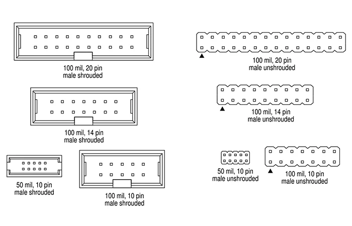
Although there is no one standard header for JTAG interfaces, several header types have become more or less standardized among manufacturers. These include the ARM JTAG 20, the ARM JTAG 14, the TI JTAG 14, the STDC14 from STMicroelectronics, the OCDS 16-pin header [pdf] from Infineon, the CoreSight 10, the CoreSight 20, the MIPI 34, and the Mictor 38. Segger defines their J-Link and J-Trace connectors to be nearly identical to the ARM JTAG 20.
Most headers are shrouded or unshrouded male headers, with 10, 14, or 20 pins, and 0.1” or 0.05” pin pitch. Examples are shown in Figure 1.
The pinouts for various JTAG interfaces (linked above) are shown in Figure 2. Here you’ll find the standard pins for JTAG (TDI, TDO, TCK, TMS, nTRST), as well as serial wire debug (SWDIO, SWCLK, SWO), and additional functions for debugging, like core tracing.
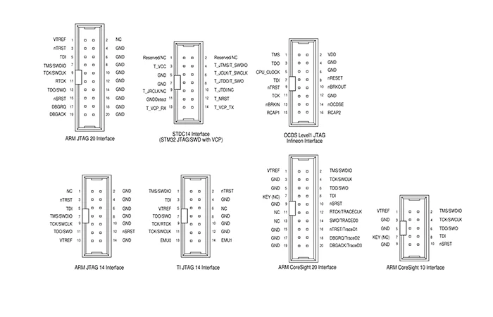
Particularly notable among the added pins are nSRST (full system reset), which forces the target to fully reset, and VTREF (voltage target reference), connected to the target supply rail for JTAG interface hardware level-shifting.
JTAG Interfaces
Several JTAG interfaces (also called JTAG debug probes) are available on the market. In the open-source hardware arena, there is the Black Magic Probe or BMP, developed by 1BitSquared and Black Sphere Technologies, used as an ARM JTAG interface, which has a large and active community supporting it. Black Magic Probe can also refer to any JTAG interface which has had its firmware replaced with the Black Magic Probe firmware.
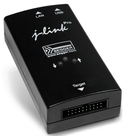
The commercial, widely used debug probes from Segger include the J-Link (shown in Figure 3) and the J-Trace, a considerably more advanced and capable debug probe suitable for industrial applications.
Specific vendors will also sell JTAG interfaces for their products. STMicroelectronics provides the STLINK series (including the STLINK/V2, and the STLINK-V3SET) for their STM8 and STM32 products, Atmel (now Microchip) provides the Atmel-ICE, NXP has the S32 Debug Probe—the list goes on.
FPGAs also use JTAG to download bit streams onto devices/memories, but these interfaces are more often called download cables. Examples include Xilinx’s Platform Cable II and Altera’s FPGA download cable, formerly known as the USB-Blaster II, now rebranded as the Intel FPGA Download Cable II.
So what exactly is going on in these devices that makes them so expensive? What functions do they support, and how does a designer use them? Generally, if you look inside a low-end debug probe, you’ll find the following:
A microcontroller as the main JTAG controller
A USB interface, which may be embedded in the microcontroller or may come separately in, for example, an FTDI chip
Level shifting circuitry for logic compatibility
Switching circuitry for enabling and disabling different paths, pull-ups, etc.
And that’s about it. As an example, look at the Black Magic Probe hardware files, available on Github. Much of the work (and cost) comes on the software end, providing powerful (sometimes real-time) debugging tools that allow a developer to make the most of the Arm CoreSight architecture.
Conclusion
To this point, we have covered the JTAG standard, including the test access port (TAP) and its state machine. In this article, we took a look at the physical side of JTAG, investigating the connectors and interfaces available to the designer from the open-source up to the commercial high-end.
From here, all that remains is a closer look at the Arm CoreSight architecture and its debug interface (ADI), which will include the increasingly common serial wire debug (SWD) JTAG alternative.
RELATED CONTENT
The JTAG Test Access Port (TAP) State Machine
JTAG Implementation in Arm Core Devices
Introduction to JTAG and the Test Access Port (TAP)
Rotary Controls For Modern Hardware Interfaces
Amphenol RF HD-EFI Series Micro-Miniature Interface Connectors | New Product Brief
What Is A JTAG Connector?
Electrical(Hardware) Protocols: FIFO / Pmod™ / JTAG及常用插座(20pin,14pin,10pin)插头类型及针序/ SPI / IIC / IIS / UART / SWD / ICSP / CANBus/ModBus的更多相关文章
- Redis常用命令入门3:列表类型
列表类型 列表类型也是一个我们很长要用到的一个类型.比如我们发博客,要用到博客列表.如果没有列表我们就只能遍历键来获取所有文章或一部分文章了,这个语法是keys,但是这个命令需要遍历数据库中的所有键, ...
- Redis常用命令入门1:字符串类型命令
Redis总共有五种数据类型,在学习的时候,一定要开一个redis-cli程序,边看边练,提高效率. 一.最简单的命令 1.获得符合规则的键名列表 keys * 这里的*号,是指列出所有的键,同时*号 ...
- Django基础篇 02- request常用属性和返回的响应类型、pycharm创建django项目
一.request常用属性 #django 请求对象里面的一些属性 print(request.method)#请求方式 print(request.body) #请求体 print(request. ...
- Redis常用命令入门4:集合类型
集合类型 之前我们已经介绍过了最基本的字符串类型.散列类型.列表类型,下面我们一起学习一下集合类型. 集合类型也是体现redis一个比较高价值的一个类型了.因为Redis的集合类型,所以我们可以很容易 ...
- Java常用类之【字符串相关类型】
一.字符相关类型 分类: 1.不可变的字符序列: String类 2.可变的字符序列: StringBuilder类--->线程不安全的 执行效率相对较高 StringBuffer类---> ...
- Redis 常用命令学四:集合类型命令
1.增加和删除命令 127.0.0.1:6379> SADD st a (integer) 1 127.0.0.1:6379> SADD st r f g (integer) 3 127. ...
- Redis 常用命令学四:列表类型命令
1.在列表两端增加值的命令 127.0.0.1:6379> lpush 1 (error) ERR wrong number of arguments for 'lpush' command 1 ...
- Redis 常用命令学习二:字符串类型命令
1.赋值与取值命令 127.0.0.1:6379> set foo helloredis OK 127.0.0.1:6379> get foo "helloredis" ...
- 测试常用shell语句——数值,数组类型;函数创建
一.特殊类型的变量 shell下默认的变量类型为字符串类型 1,数值类型 如果进行数值运算,有这么几种方法 方法一: declare -i sum sum=+ echo $sum 方法二: sum=$ ...
- S3C2440A特殊寄存器
S3C2440A特殊寄存器 特殊寄存器有: 输入输出端口 存储器控制器 NANDFLASH 看门狗定时器 时钟和电源管理 PWM定时器 UART USB设备 中断控制器 DMA LCD控制器 RTC ...
随机推荐
- 小模型工具调用能力激活:以Qwen2.5 0.5B为例的Prompt工程实践
在之前的分析中,我们深入探讨了cline prompt的设计理念(Cline技术分析:prompt如何驱动大模型对本地文件实现自主变更),揭示了其在激发语言模型能力方面的潜力.现在,我们将这些理论付诸 ...
- 想让鸿蒙应用快的“飞起”,来HarmonyOS开发者官网“最佳实践-性能专区”
在鸿蒙应用开发过程中,应用侧流畅运行体验是开发者非常关注的部分.为此,华为HarmonyOS开发者官网推出了"最佳实践-性能专区"(以下简称"性能专区"),通过 ...
- 深入解析Tortoise-ORM关系型字段与异步查询
title: 深入解析Tortoise-ORM关系型字段与异步查询 date: 2025/05/01 00:12:39 updated: 2025/05/01 00:12:39 author: cmd ...
- SpringBoot整合Web层技术
目录 1 SpringBoot整合Web层技术 1.1 SpringBoot整合Servlet 1.1.1 方式一 通过注解扫描完成Servlet组件的注册 1.1.1.1 创建Servlet 1.1 ...
- 代码随想录第十七天 | Leecode 654. 最大二叉树、617. 合并二叉树、700. 二叉搜索树中的搜索、98. 验证二叉搜索树
Leecode 654. 最大二叉树 题目描述 给定一个不重复的整数数组 nums . 最大二叉树 可以用下面的算法从 nums 递归地构建: 创建一个根节点,其值为 nums 中的最大值. 递归地在 ...
- #React中类组件中关于回调函数的一个问题
在ES6中,类中定义的方法,是放在原型对象的,供实例对象引用. //创建一个Person类 class Person { constructor(name,age) { this.name = nam ...
- 关于 Newtonsoft.Json 和 System.Text.Json 混用导致的的序列化不识别的问题
最近,我在做一个我们一个产品的OTA的功能,在调试跟后台对接Json数据的时候,发现序列化的数据一直跟期待的不一致.这让我很纳闷,明明一个简单的序列化和反序列化的问题,怎么数据就不对了.于是乎,就直接 ...
- AtCoder Beginner Contest 382-E
Problem 有无数包牌,每包有 \(N\) 张牌.在每一包牌中, 第 \(i\) 张牌是稀有牌,概率为 \(P_i\%\).每张牌是否稀有与其他牌是否稀有无关. 逐一打开包装,并获得每包中的所有卡 ...
- .NET 9中的异常处理性能提升分析:为什么过去慢,未来快
一.为什么要关注.NET异常处理的性能 随着现代云原生.高并发.分布式场景的大量普及,异常处理(Exception Handling)早已不再只是一个冷僻的代码路径.在高复杂度的微服务.网络服务.异步 ...
- 「Log」2023.8.22 小记
序幕 早上不到七点到校,6bit 早就到了. 写博客写博客写博客. \(\texttt{8:21}\):把 LCT 的博客写查不多了,SAM 的还是再咕咕咕,先打代码. 学长讲题,LCT 的,讲完吃饭 ...