PID控制器(比例-积分-微分控制器)- IV
调节/测量放大电路电路图:PID控制电路图

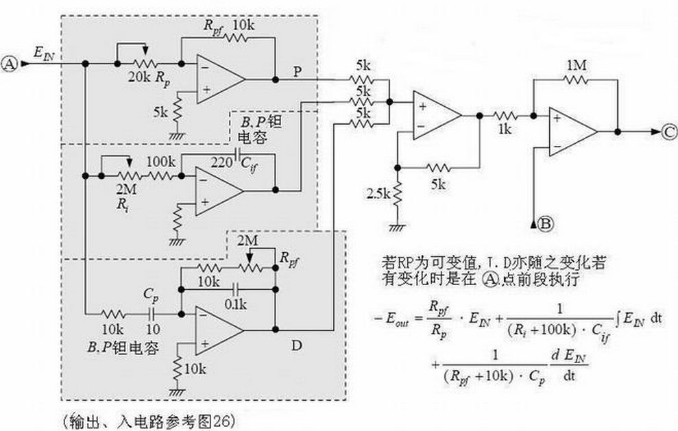
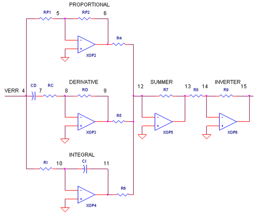
如图是PlD控制电路,即比例(P)、积分(I)、微分(D)控制电路。
A1构成的比例电路与环路增益有关,调节RP1,可使反相器的增益在0·5一∞范围内变化;
A2是积分电路,积分时间常数可在22一426S范围内变化;
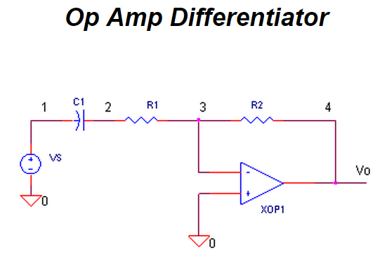
A3是微分电路,时间常数由Cl(Rl+R(RP3))决定;
A4将比例、积分、微分各电路输出倒相后合成为U。
Controller Circuit
This circuit is the basis of a temperature controller.
Study it and then answer the questions that follow.
The questions have links to outline answers but please resist the temptation to look at these
until you have written down your own answers to all the questions.
- What does the circuit do and how does it work?
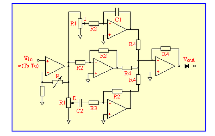
The circuit is a form of PID controller.
The input signal is buffered and amplified by a non-inverting amplifier and the gain of this stage defines the proportional gain P of the controller.
The amplified error signal passes in parallel through
an integrator (top) a unity-gain amplifier (middle) and a differentiator (bottom) all of which have inverting behaviour.
Their outputs are then summed and inverted by the final op-amp and passed to the output.
The potentiometers labelled D and I control the proportions in which derivative and integral fractions contribute
to the output signal which is proportional to the power W to be supplied to the heater. - What additional circuit is needed between the output and the heater?
A heater-driver that ensures that the power dissipated in the heater is proportional to the output voltage.
This is usually either a square-rooter if the heater is to be driven by DC, or with AC heaters some type of pulse-width modulator. - Why is there a diode in series with the output?
The heater power can only be positive or zero so the diode keeps the output signal within these constraints. - Why might one want to make R2 much larger than R1?
A low value of R2 would 'load' the potentiometers and impair the linear relationship between control position and gain. - What is the purpose of R3?
The gain of a differentiator increases in proportion to frequency and without R3 it would only be limited by the,
normally unnecessarily high, open-loop gain of the op-amp.
R3 limits the gain at high frequencies reducing the noise of the system. - What might be the most serious effect of op-amp offset voltages currents and bias?
It is most likely to be troublesome by causing an offset between the set-point and oven temperatures.
Under some circumstances the integrator may drift and eventually saturate which would prevent it from working properly. - How might the impact of op-amp offset and bias be reduced?
The first thing to try would be a resistor, equal in value to R2, between the positive input of the integrating op-amp
and ground to eliminate the common-mode bias current.
Selecting an op-amp with a good input-offset performance would be the next step. - How would you consider improving the circuit?
The improvements suggested in the previous answer would be a good start.
The diode at the output could be replaced by an active rectifier for greater precision at low heater powers.
Some method of reseting the integrator would help and maybe a circuit implement
the 'Limit I?' function of the interactive simulation.
Meters to indicate heater power and an error signal are helpful to the person who has to tune a controller for a particular oven.
PID Controller

Tuning the PID controller can be like learning to roller blade, ski or maybe riding a bull.
Until you've done it a few times, the literature you've read really doesn't hit home. But after after few attempts (and falls),
you find it wasn't so bad after all - in fact it was kind of fun!
The PID controller is every where - temperature, motion, flow controllers - and its available in analog and digital forms.
Why use it? It helps get your output (velocity, temperature, position) where you want it,
in a short time, with minimal overshoot, and with little error.
In many applications the PID controller can do the job - but as usual, with compromises.
After a short intro to the PID terms and an example control system, you'll get a chance tune a PID controller.
THE CONTROL SYSTEM
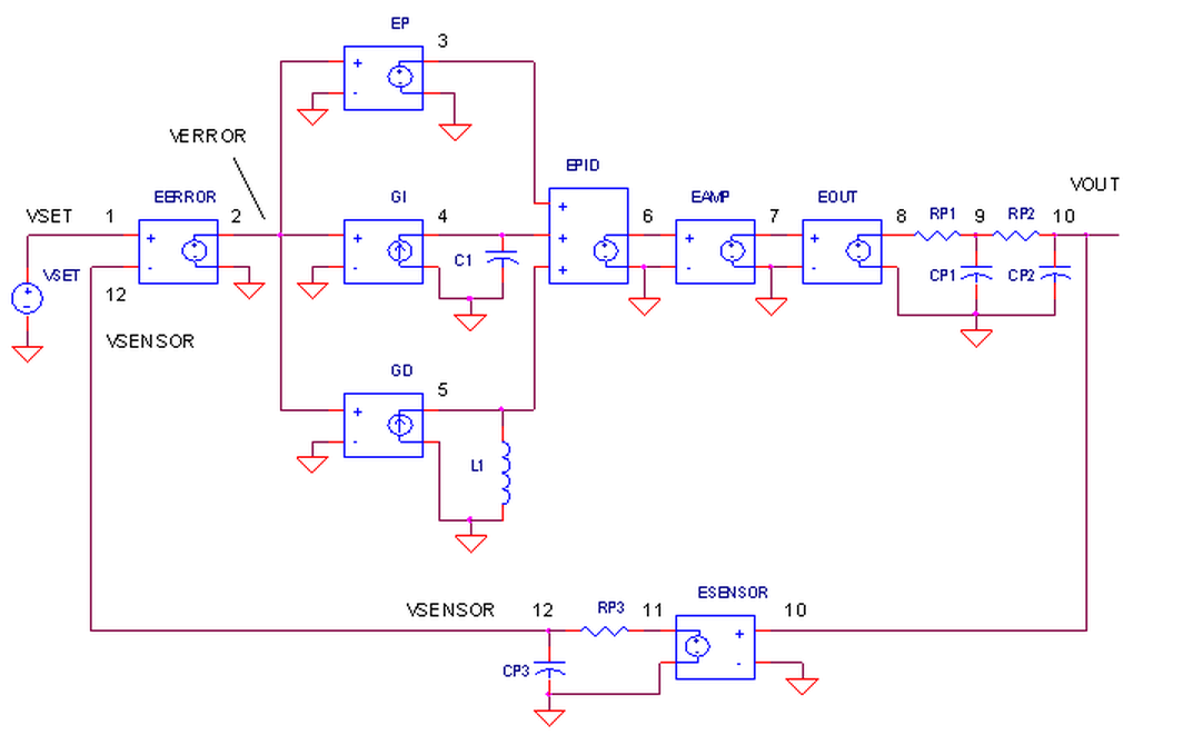
The SPICE circuit for the Control System looks pretty much like the block diagram.
PID CONTROLLER.
How do we create the PID terms? To get theProportional term, EP multiples Verror at V(2) by a fixed gain of 1 - easy enough! To get the Integral term, current source GI converts V(2) to a current and integrates it on C1=1F. Finally, theDerivative term is created by GD converting V(2) to a current and forcing it through L1. The resulting voltage becomes V(5) = L1 di / dt. A quick substitution of L1 = 1 H and i = Verror gets you V(5) = d Verror / dt.
OUTPUT PROCESS.
EOUT represents a very simplified model of a process to be controlled like motor velocity or heater temperature. The gain of 100 could represent an output transfer function of 100 RPM / V or 100 ° C / V. To include the effects of the motor's inertia or heater's thermal mass, we've added some time delay into the output using two cascaded RC filters. Although Vout is simulated in volts, we know it really represents other variables like velocity in RPM or temperature in °C.
SENSOR.
The sensor tells you, typically by a voltage, what's happening at the control system output. For motor velocity, a tachometer could generate 1 V / 100 RPM; for temperature, a thermistor circuit could produce 0.01 V / deg C. ESENSOR models this feedback device. Because a sensor does not respond instantly, an RC filter is also added here to model its finite response time.
TUNING THE PID CONTROLLER
Although you'll find many methods and theories on tuning a PID,
here's a straight forward approach to get you up and soloing quickly.
1. SET KP. Starting with KP=0, KI=0 and KD=0, increase KP until the output starts overshooting and ringing significantly.
2. SET KD. Increase KD until the overshoot is reduced to an acceptable level.
3. SET KI. Increase KI until the final error is equal to zero.
Run a simulation of the circuit file PID1.CIR.
VSET generates a 10V step input voltage to the control system.
You can adjust the PID terms at the EPID source that adds the P, I and D terms at V(3), V(4) and V(5).
Initially, the PID multipliers are set to KP=, KI= and KD=.
EPID 6 0 POLY(3) (3,0) (4,0) (5,0) 0 1 0 0
SET KP.
Plot the system input V(1) and the sensor output (12). Although the response looks smooth, what is the sensor voltage compared to the desired 10V? The output falls short by 5V! To reduce this error, increase KP to 10 (Change EPID to look like ... 10 0 0 ). Wow, the output now reaches 9V, reducing the error to 1V. But as you can see, the output is getting wild with overshoot and ringing. Push KP up higher to 20 or 30. Yes, the error reduces, but the overshoot gets worse. Eventually, your system will become unstable and break out into song (oscillate). Back off KP to 20 or so.
SET KD.
The derivative term can rescue the response by counteracting the KP drive when the output is changing. Start with a small value like KD=0.2 and rerun the simulation (Change EPID to look like ...
20 0 0.2 ). Now you're wrestling control back into the system - the ringing and overshoot are reduced! Crank up KD some more. Improvement should continue to a point where the system becomes less stable and overshoot increases again. Return KD to around 0.5.
SET KI.
With KP=20, KI=0 and KD=0.5 the response looks respectable, but the final error is a disappointing 0.5V (or 5%)! Now, try the KI term. This will integrate the remaining error into a drive signal big enough to reduce the error further. Start with KI = 10 ( EPID should look like ... 20 10 0.5 ). Check out the last half of the V(12) - the sensor output moves slowly toward 10V! You might want to put up a cursor on the plot to monitor the exact value of V(12). The bigger you make KI, the faster it will move toward 10V. Like the other terms, a value is reached where the KI does more harm than good as the system becomes less stable.
DIVING DEEPER
Diving a little deeper you can get a clearer view of the PID components. Before we go beneath the surface, set KP=, KI= and KD=.
Run a couple of simulations with KP=10 and KP 20. Plot V(1) and V(12). What is the final error for each case? You may have noticed the errors of 1 and 0.5V are proportional to the gains of 10 and 20. You can estimate the error by
Verror ≈ Vset / KP
for large KP. What kind of gain do you need for a 1% error? You can easily calculate it as a gain of 100. However, we've already seen how large gain cause overshoot, ringing and oscillations! KP can't do it alone.
KD counteracts KP - let's see how. Set KP back to 10 and run a simulation. Plot the P function V(3) which is really Verror. Now plot the D term V(5) which we know is dVerror / dt. To get a good view of D, set the Y-Axis limits to +100 /-200V. Notice how dVerror / dt swings negative when Verror is initially positive. How does this help? Essentially D counteracts the P term potentially reducing ringing and oscillations. The nice thing about the D term is that it goes to zero as the output settles. This makes sense - no change in output, no derivative term. Add in some of the D function by setting the multipliers to KP=, KI= and KD=0.5. The initial overshoot should be significantly reduced.
We've seen how a large gain produces a small error. However, big KP gets you into big trouble with overshoot and ringing. Alternatively, an integrator can also give you a big gain by accumulating even a small error over time. Run a simulation with KP=, KI= and KD=, KI= and KD=0.5. The I term completes the controller's job by moving the output toward an error of zero.
SIMULATION NOTE
Need a handy way to combine multiple signals such as the PID sum? A controlled source can be a function of multiple inputs described by a polynomial. What is this polynomial? The equation is defined by a coefficient list at the end of the statement. The example below
EPID 6 0 POLY(3) (3,0) (4,0) (5,0) 0 10 2 1
creates a polynomial of the form
V(6,0) = + ∙ V(3,0) + ∙ V(4,0) + 1 ∙ V(5,0)
or more generally,
VO = k0 + k1∙V1 + k2∙V2 + k3∙V3
In fact, you can get higher order terms and cross terms by extending the coefficient list
VO = ...+ k4∙V1∙V1 + k5∙V1∙V2 + k6∙V1∙V3 +
+ k7∙V2∙V2 + k8∙V2∙V3 +
+ k9∙V3∙V3
If you're not using a term, you need to put a 0 in its place; you can't just leave it out.
This feature is great for simpler polynomials. Keeping track of the coefficient list for large polynomials can get crazy fast.
We've all heard about the wonders of the PID controller, bringing a system's output
- temperature, velocity, light - to its desired set point quickly and accurately.
But now, your boss says okay, design one for us.
Although there's a number of ways to do it, the circuit above nicely separates the three terms into three individual op amp circuits.
We'll build it in SPICE, test each term and finally place it inside a motor speed controller for you to tune.
If you wish, take a quick review ofPID Control.
THE PID CONTROLLER
You've probably seen the terms defined before:
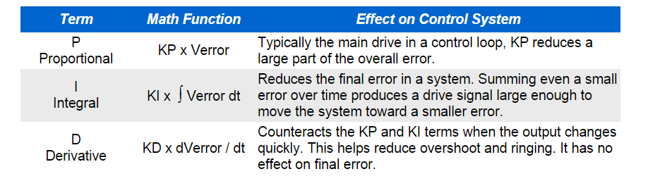
P -Proportional, I - Integral, D - Derivative.
These terms describe three basic mathematical functions applied to the error signal ,
Verror = Vset - Vsensor.
This error represents the difference between where you want to go (Vset), and where you're actually at (Vsensor).
The controller performs the PID mathematical functions on the error and applies the their sum to a process (motor, heater, etc.)
So simple, yet so powerful! If tuned correctly, the signal Vsensor should move closer to Vset.
Tuning a system means adjusting three multipliers Kp, Ki and Kd adding in various amounts of these functions
to get the system to behave the way you want.
The table below summarizes the PID terms and their effect on a control system.
THE PID CONTROLLER
What basic components are needed for a servo system?
Many look similar to the circuit below. The error amp gives you a constant reality check.
How? It compares where you want to go, Vset, with where you're at now, Vsensor,
by calculating the difference between the two, Verr = Vset - Vsensor.
The PID controller takes this error and determines the drive voltage applied
to the process in an attempt to bring Vset = Vsensor or Verr = 0.
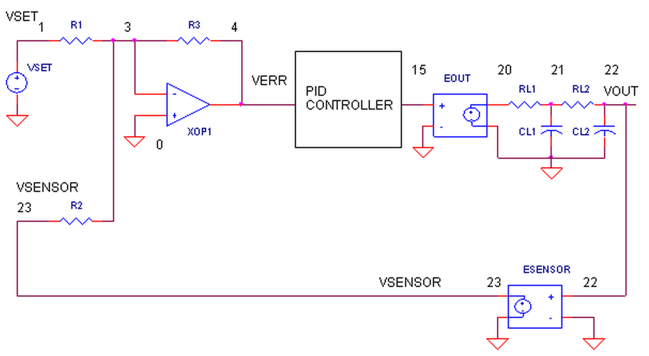
ERROR AMPLIFIER. A classic circuit for calculating the error is a summing op amp.
In the controller, XOP1 performs the error calculation. Remembering that the summing amp is an inverting amp,
we calculate its output using R1 = R2 = R3 = 10 kΩ.
Verr = - (Vset / R1 + Vsensor / R2) ∙ R3 = (Vset + Vsensor) ∙ (10 k / 10 k) = - ( Vset + Vsensor )
But how does the summer calculate a difference?
Well, it does require that your sensor circuit produce a negative output voltage.
Assuming that Vsensor is the negative of the actual sensor voltage Vsensor = - Vsens, you get the difference.
Verr = -( Vset - Vsens )
You can look at the error amp's function this way. When Vsensor is exactly the negative ofVset, the currents through R1 and R2,
equal and opposite, cancel each other as they enter the op amps's summing junction.
You end up with zero current through R3 and of course 0V, or zero error, at the output.
Any difference between Vset and -Vsensor, results in an error voltage at the output that the PID controller can act upon.
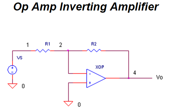
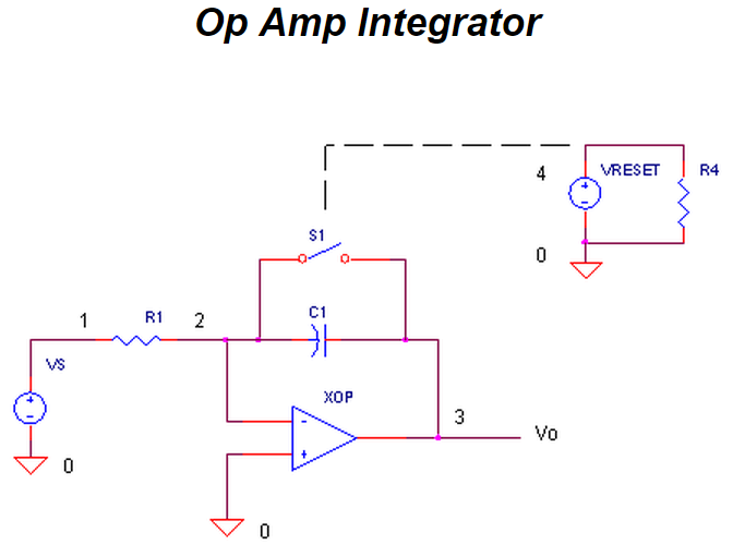
OP AMP PID CONTROLLER.
How do we get the PID terms from the error voltage Verr?
We enlist three simple op amp circuits.
If you need, take a review of the op amp amplifier,integrator and differentiator circuits.

Lastly, we need to add the three PID terms together. Again the summing amplifier XOP5 serves us well.
Because the error amp, PID and summing circuits are inverting types,
we need to add a final op amp inverter XOP6 to make the final output positive, given a positive Vset.
OUTPUT PROCESS.
EOUT represents a very simplified model of a process to be controlled, such as motor velocity for example.
The gain of 100 could represent an output transfer function of 100 RPM / V.
To include the effects of the motor's inertia, we've added some time delay into the output using two cascaded RC filters.
Although Vout is simulated in volts, we know it really represents RPM.
SENSOR.
The sensor tells you the actual velocity at the motor, 1 V / 100 RPM for this tachometer.
ESENSOR models this feedback device. Note, this sensor block actually produces a negative output voltage,
the proper input polarity for your error amplifier as mentioned above.
PID控制器(比例-积分-微分控制器)- IV的更多相关文章
- PID控制器(比例-积分-微分控制器)- I
形象解释PID算法 小明接到这样一个任务: 有一个水缸点漏水(而且漏水的速度还不一定固定不变),要求水面高度维持在某个位置,一旦发现水面高度低于要求位置,就要往水缸里加水. 小明接到任务后就一直守在水 ...
- PID控制器(比例-积分-微分控制器)- II
Table of Contents Practical Process Control Proven Methods and Best Practices for Automatic PID Cont ...
- PID控制器(比例-积分-微分控制器)- V
Linear Actuator - PID Control Introduction This application guide is designed to explain the basics ...
- PID控制器(比例-积分-微分控制器)- III
PID Controller Algorithms Controller manufacturers arrange the Proportional, Integral and Derivative ...
- [Fundamental of Power Electronics]-PART II-9. 控制器设计-9.5 控制器的设计
9.5 控制器设计 现在让我们来考虑如何设计控制器系统,来满足有关抑制扰动,瞬态响应以及稳定性的规范或者说设计目标.典型的直流控制器设计可以用以下规范定义: 1.负载电流变化对输出电压调节的影响.当负 ...
- .NET/ASP.NET MVC Controller 控制器(深入解析控制器运行原理)
阅读目录: 1.开篇介绍 2.ASP.NETMVC Controller 控制器的入口(Controller的执行流程) 3.ASP.NETMVC Controller 控制器的入口(Controll ...
- 创建控制器的方法、控制器加载view过程、控制器view的生命周期、多控制器组合
在介绍四大对象的那篇博客中,可以基本了解到程序启动的过程: main-->UIApplicationMain-->创建UIApplication的实例和app代理AppDelegate的实 ...
- 集合视图控制器(CollectionViewController) 、 标签控制器(TabBarController) 、 高级控件介绍
1 创建集合视图,设置相关属性以满足要求 1.1 问题 集合视图控制器UIConllectionViewController是一个展示大量数据的控制器,系统默认管理着一个集合视图UICollectio ...
- 【iOS开发-21】UINavigationController导航控制器初始化,导航控制器栈的push和pop跳转理解
(1)导航控制器初始化的时候一般都有一个根视图控制器,导航控制器相当于一个栈,里面装的是视图控制器,最先进去的在最以下,最后进去的在最上面.在最上面的那个视图控制器的视图就是这个导航控制器对外展示的界 ...
随机推荐
- spring事物深入了解
1.问题 1.以前对事物的了解只是停留在声明式事物,配置xml,或使用注解,事物的传播行为也只用过REQUIRED和SUPPORTS,可以说对事物的了解很模糊. 2.直到在开发中遇到问题.. 问题的描 ...
- Ex 6_16 旧货销售问题_第七次作业
即可 子问题定义:定义数组B(S,j),其中 B(S,j)表示在子集S中结束位置为j的子问题的最大收益值,其中j的前一个地点有两种情况,第一种情况是某个拍卖会 另一种情况是从家里出发. 递归关系: 初 ...
- mysql当查询某字段结果为空并赋值
1 代码 1.1 当当前字段为空,查询结果返回“none”,并且统计出现频率 select case when 字段 is null then 'none' else 字段 end as 字段, co ...
- XHR简介
在XHR诞生前,网页要获取客户端和服务器的任何状态更新,都需要刷新一次,在XHR诞生后就可以完全通过JS代码异步实现这一过程.XHR的诞生也使最初的网页制作转换为开发交互应用,拉开了WEB2.0的序幕 ...
- poj2464扫描线好题,树状数组解法
用树状数组解比线段树快了好多,难度也下降许多 分别用两个树状数组维护当前扫描线左侧和右侧的点,离散化y轴即可 #include<iostream> #include<cstring& ...
- poj1511,线段树扫描线面积
经典题,线段树扫描线其实类似区间更新,一般的做法是想象一根扫描线从上扫到下或者从左扫到右,本题的做法是从上扫到下 只要扫到了一根水平线,就将其更新到线段树对应区间中,区间和它的子区间是独立更新的 #i ...
- 性能测试二十九:Dubbo框架测试脚本编写
测试脚本编写 新建一个folder命名为lib,用于存放依赖包 把以下jar全部拷进lib下,并build path 找开发要 真正要测试的以jar包形式存在的代码的类, 打开看一下 放到lib并bu ...
- 性能测试二十五:redis-cli 命令总结
常用命令dbsize:查看redis中的kv数量 keys *:查看redis中所有的keyset key_1 v_1:新增一个key_1,包含v_1get key_1:查看key_1中的内容del ...
- 步步为营-59-svn简介
说明:版本控制器Svn的使用,安装教程不再多说 VisualSVN-Server--项目经理 TortoiseSVN--右击的时候显示 VisualSVN-- visual studio中使用 1 搭 ...
- 步步为营-20-XML
说明:可扩展标记语言 eXtensible Markup Language--区分大小写 涉及到的知识点:DOM 文档对象模型 文本文件存储数据缺点:1,不易读取.2,易乱码 1 通过代码创建一个xm ...