
Multiplexing SDIO Devices Using MAX II or CoolRunner-II CPLD
XAPP906
Supporting Multiple SD Devices with CoolRunner-II CPLDs
There has been an increasing demand to add multiple Secure Digital (SD) devices in a single system. Whether the system application calls for a combination of SD memory ports, 802.11 SDIO cards or any other SDIO expansion cards, there is no question that the SD protocol is currently hitting its stride. The problem, however, is that most host devices (i.e. Intel PXA270, TI OMAP, or Qualcomm MSM processors) only provide a single SD interface. Fortunately, CoolRunner-II CPLDs can be used to allow host devices to support any number of SD devices. This application note details a scalable, auto-sensing bidirectional multiplexer based design.
Creating an SD Multiplexer Using CoolRunner-II Figure 1 shows a generalized CoolRunner™-II usage model to incorporate any number of SD ports for a given host device that only has a single native SD interface. The CoolRunner-II CPLD is placed between the host controller and the SD devices. As such, the CoolRunner-II part performs a bidirectional multiplexing function, allowing the host to communicate with any selected SD Device. More importantly, this design has no directional control pins, which means that the CoolRunner-II automatically detects the direction of data flow.

This implementation is extremely flexible and scalable, meaning that the number of SD ports can be increased or decreased as desired. The design also supports any of the defined SD card modes -- SPI, 1-bit, or 4-bit data modes. While the primary purpose of using a CoolRunner-II device in this type of application is to provide additional SD ports to the host controller, secondary benefits include level translation and logic isolation between the host and the SD card. Figure 1 shows the case where the host is 1.8V, but the SD Devices are 3.3V. CoolRunner-II CPLDs provide negligible standby current and ultra low dynamic power consumption. Hence, incorporating a CoolRunner-II CPLD will not have a significant impact upon your power budget.
Compliance With the SDA Specification
The SDA specification states that one SD bus can only support one SD device. The clock pin can be shared, but DAT[3:0] and CMD lines must be unique for every SD device. See Figure 2 for additional details.

This reference design is fully compliant with the SDA Specification. The following section will show you how to satisfy the above requirements while supporting any number of SD devices using a controller with a single bus.
Block Diagram
A block diagram showing typical use of this design for two SD devices sharing the same SD host interface can be seen in Figure 3. Conceptually, the design can be viewed and used as a bidirectional multiplexer. The host device controls the CoolRunner-II CPLD via the ’Select’ signals, thereby dictating which SD device to communicate with. Once an SD device has been selected, the logic in the CoolRunner-II device automatically detects the direction of data flow, and allows data to flow accordingly (either from the host to the SD card or from the SD card to the host). A directional control pin is not required, thereby making this design easy to use.

The host can access each SD device individually without affecting the state of the other when the multiplexer is switched accordingly. If neither the host nor the SD is driving data, the CoolRunner-II CPLD allows the system to be in the default high impedance with weak pull-up state. The primary purpose of this circuit is to provide additional SD capability to the host, but this circuit can also be used to provide level translation and/or logic isolation.
Implementation Details
Figure 4 shows the actual logic circuit for a 1:2 bidirectional multiplexer design, which can be found described using VHDL (see “VHDL Download”).
In the initial condition or idle state, the Host and SD Cards should be high impedance with a weak pull-up.
Hence, the circuit in Figure 4 is designed to tristate the CoolRunner-II device’s output buffers, thereby allowing the external pull-up resistors to take effect.
Register A (A_REG) and Register B (B_REG) are both designed to be initialized to logic ’0’ upon power-up.
The SD Cards are selected via the ’Select’ inputs to the CPLD.
When ’Select’ is logic ’0’, SD1 is chosen and when ’Select’ is logic ’1’, the SD2 device is chosen.
For simplicity while describing this circuit, let us assume in the following discussion that the Host is only choosing to communicate with SD1. < ’Select’ is logic ’0’ >
The autodirectional control aspect of this design is implemented in the following manner -- A transaction is initiated when either the host or SD1 drives Low.
For example, if the host wants to send data to the SD1 device, the host would begin by driving the A side Low.
Upon driving Low, the logic in the circuit detects the Low going edge and responds by enabling the ’B’ output buffer,
but continues to keep the ’A’ output buffer disabled.
Specifically, when A is driven Low, a rising edge is delivered to the clock input of A_REG.
After clocking, A_REG’s Q output becomes logic ’1’ and therefore prevents B_REG from receiving a clocking event.
In parallel with the A_REG clocking and triggering, gate B1 outputs a logic ’1’ when A goes Low.
This enables the ’B’ Output Buffer and, ultimately, B will follow A and drive Low.
Conversely, when it is driven from Low to High, gate B1 outputs a Low and tristates the B output buffer.
This forces B to go High (via the external pull-up resistor).
Once the A and B sides are both High, A_REG and B_REG are reset to 0.
This process is repeated indefinitely.
The reverse happens when SD1 attempts to drive data toward the host.
Additionally, if the host wishes to communicate with the SD2 device,
the ’Select’ inputs to the circuit are set to a logic ’1’ and the sequence of events are similar to the above.

Simulation Results
Functional and timing simulations have been extensively performed on this circuit using ModelSim,
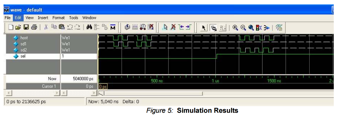
and test stimuli have been included with the VHDL download. Figure 5 shows some simulation results.
In the first part of Figure 5, the Select input is held Low.
A dotted white line denotes a "Weak 1" condition, or, in other words, represents a pulled up state.
In the first transaction, the host attempts to drive data toward SD1, and SD1 follows accordingly.
Immediately after, the SD1 device attempts to drive data toward the host, and the host follows.
Similar events happen when the Select input is driven High.
The host drives data toward the SD2 device, then the SD2 device drives data toward the host.
----------------------------------------------------------------------------------

-- Company:

-- Engineer:

--

-- Create Date:    :: //

-- Design Name:

-- Module Name:    SDIO - Behavioral

-- Project Name:

-- Target Devices:

-- Tool versions:

-- Description:

--

-- Dependencies:

--

-- Revision:

-- Revision 0.01 - File Created

-- Additional Comments:

--

----------------------------------------------------------------------------------

library IEEE;

use IEEE.STD_LOGIC_1164.ALL;

use IEEE.STD_LOGIC_ARITH.ALL;

use IEEE.STD_LOGIC_UNSIGNED.ALL;

---- Uncomment the following library declaration if instantiating

---- any Xilinx primitives in this code.

library UNISIM;

use UNISIM.VComponents.all;

entity SDIO2 is

    Port ( h_clk : in  STD_LOGIC;

           h1_cmd : inout  STD_LOGIC;

           h1_dat3 : inout  STD_LOGIC;

           h1_dat2 : inout  STD_LOGIC;

           h1_dat1 : inout  STD_LOGIC;

           h1_dat0 : inout  STD_LOGIC;

            c1_clk : out  STD_LOGIC;

           c1_cmd : inout  STD_LOGIC;

           c1_dat3 : inout  STD_LOGIC;

           c1_dat2 : inout  STD_LOGIC;

           c1_dat1 : inout  STD_LOGIC;

           c1_dat0 : inout  STD_LOGIC;

           --

           h2_cmd : inout  STD_LOGIC;

           h2_dat3 : inout  STD_LOGIC;

           h2_dat2 : inout  STD_LOGIC;

           h2_dat1 : inout  STD_LOGIC;

           h2_dat0 : inout  STD_LOGIC;

            c2_clk : out  STD_LOGIC;

           c2_cmd : inout  STD_LOGIC;

           c2_dat3 : inout  STD_LOGIC;

           c2_dat2 : inout  STD_LOGIC;

           c2_dat1 : inout  STD_LOGIC;

           c2_dat0 : inout  STD_LOGIC;

            sel : in STD_LOGIC

            --test : in STD_LOGIC --simulation purpose only

            );

              attribute KEEP: string;

end SDIO2;

architecture Behavioral of SDIO2 is

signal test: std_logic;

signal h1_cmd_oe, h1_cmd_reg, h1_cmd_clk, h1_cmd_buf, h1_cmd_reset: std_logic;

signal c1_cmd_oe, c1_cmd_reg, c1_cmd_clk, c1_cmd_buf, c1_cmd_reset: std_logic;

attribute KEEP of h1_cmd_buf: signal is "TRUE";

attribute KEEP of c1_cmd_buf: signal is "TRUE";

signal h1_dat3_oe, h1_dat3_reg, h1_dat3_clk, h1_dat3_reset: std_logic;

signal c1_dat3_oe, c1_dat3_reg, c1_dat3_clk, c1_dat3_reset: std_logic;

signal h1_dat2_oe: std_logic;

signal c1_dat2_oe: std_logic;

signal h1_dat1_oe: std_logic;

signal c1_dat1_oe: std_logic;

signal h1_dat0_oe: std_logic;

signal c1_dat0_oe: std_logic;

------

signal h2_cmd_oe, h2_cmd_reg, h2_cmd_clk, h2_cmd_buf, h2_cmd_reset: std_logic;

signal c2_cmd_oe, c2_cmd_reg, c2_cmd_clk, c2_cmd_buf, c2_cmd_reset: std_logic;

attribute KEEP of h2_cmd_buf: signal is "TRUE";

attribute KEEP of c2_cmd_buf: signal is "TRUE";

signal h2_dat3_oe, h2_dat3_reg, h2_dat3_clk, h2_dat3_reset: std_logic;

signal c2_dat3_oe, c2_dat3_reg, c2_dat3_clk, c2_dat3_reset: std_logic;

signal h2_dat2_oe: std_logic;

signal c2_dat2_oe: std_logic;

signal h2_dat1_oe: std_logic;

signal c2_dat1_oe: std_logic;

signal h2_dat0_oe: std_logic;

signal c2_dat0_oe: std_logic;

begin

test <= '';

c1_clk <= h_clk and not sel;

--

h1_cmd_oe <= not h1_cmd_reg and not c1_cmd and not test and not sel;

h1_cmd <= '' when (h1_cmd_oe = '') else 'Z';

h1_cmd_clk <= not h1_cmd_reg and not c1_cmd_reg and not h1_cmd_buf;

h1_cmd_reset <= h1_cmd and c1_cmd;

h1_cmd_inst : buf

port map(

    O => h1_cmd_buf,

    I => h1_cmd

    );

process(h1_cmd_clk, h1_cmd_reset)

begin

    if(h1_cmd_reset = '') then

        h1_cmd_reg <= '';

    elsif(h1_cmd_clk'event and h1_cmd_clk = '') then

        h1_cmd_reg <= '';

    end if;

end process;

--

c1_cmd_oe <= not c1_cmd_reg and not h1_cmd and not test and not sel;

c1_cmd <= '' when (c1_cmd_oe = '') else 'Z';

c1_cmd_clk <= not c1_cmd_reg and not h1_cmd_reg and not c1_cmd_buf;

c1_cmd_reset <= c1_cmd and h1_cmd;

c1_cmd_inst : buf

port map(

    O => c1_cmd_buf,

    I => c1_cmd

    );

process(c1_cmd_clk, c1_cmd_reset)

begin

    if(c1_cmd_reset = '') then

        c1_cmd_reg <= '';

    elsif(c1_cmd_clk'event and c1_cmd_clk = '') then

        c1_cmd_reg <= '';

    end if;

end process;

--

h1_dat3_oe <= not h1_dat3_reg and not c1_dat3 and not test and not sel;

h1_dat3 <= '' when (h1_dat3_oe = '') else 'Z';

h1_dat3_clk <= not h1_dat3_reg and not c1_dat3_reg and ((not h1_dat3) or (not h1_dat2) or (not h1_dat1) or (not h1_dat0));

h1_dat3_reset <= h1_dat3 and c1_dat3 and h1_dat2 and c1_dat2 and h1_dat1 and c1_dat1 and h1_dat0 and c1_dat0;

process(h1_dat3_clk, h1_dat3_reset)

begin

    if(h1_dat3_reset = '') then

        h1_dat3_reg <= '';

    elsif(h1_dat3_clk'event and h1_dat3_clk = '') then

        h1_dat3_reg <= '';

    end if;

end process;

--

c1_dat3_oe <= not c1_dat3_reg and not h1_dat3 and not test and not sel;

c1_dat3 <= '' when (c1_dat3_oe = '') else 'Z';

c1_dat3_clk <= not c1_dat3_reg and not h1_dat3_reg and ((not c1_dat3) or (not c1_dat2) or (not c1_dat1) or (not c1_dat0));

c1_dat3_reset <= h1_dat3 and c1_dat3 and h1_dat2 and c1_dat2 and h1_dat1 and c1_dat1 and h1_dat0 and c1_dat0;

process(c1_dat3_clk, c1_dat3_reset)

begin

    if(c1_dat3_reset = '') then

        c1_dat3_reg <= '';

    elsif(c1_dat3_clk'event and c1_dat3_clk = '') then

        c1_dat3_reg <= '';

    end if;

end process;

--

h1_dat2_oe <= not h1_dat3_reg and not c1_dat2 and not test and not sel;

h1_dat2 <= '' when (h1_dat2_oe = '') else 'Z';

--

c1_dat2_oe <= not c1_dat3_reg and not h1_dat2 and not test and not sel;

c1_dat2 <= '' when (c1_dat2_oe = '') else 'Z';

--

h1_dat1_oe <= not h1_dat3_reg and not c1_dat1 and not test and not sel;

h1_dat1 <= '' when (h1_dat1_oe = '') else 'Z';

--

c1_dat1_oe <= not c1_dat3_reg and not h1_dat1 and not test and not sel;

c1_dat1 <= '' when (c1_dat1_oe = '') else 'Z';

--

h1_dat0_oe <= not h1_dat3_reg and not c1_dat0 and not test and not sel;

h1_dat0 <= '' when (h1_dat0_oe = '') else 'Z';

--

c1_dat0_oe <= not c1_dat3_reg and not h1_dat0 and not test and not sel;

c1_dat0 <= '' when (c1_dat0_oe = '') else 'Z';

-------------------------------------------------------------------------------

c2_clk <= h_clk and sel;

-------------------------------------------------------------------------------

h2_cmd_oe <= not h2_cmd_reg and not c2_cmd and not test and sel;

h2_cmd <= '' when (h2_cmd_oe = '') else 'Z';

h2_cmd_clk <= not h2_cmd_reg and not c2_cmd_reg and not h2_cmd_buf;

h2_cmd_reset <= h2_cmd and c2_cmd;

h2_cmd_inst : buf

port map(

    O => h2_cmd_buf,

    I => h2_cmd

    );

process(h2_cmd_clk, h2_cmd_reset)

begin

    if(h2_cmd_reset = '') then

        h2_cmd_reg <= '';

    elsif(h2_cmd_clk'event and h2_cmd_clk = '') then

        h2_cmd_reg <= '';

    end if;

end process;

--

c2_cmd_oe <= not c2_cmd_reg and not h2_cmd and not test and sel;

c2_cmd <= '' when (c2_cmd_oe = '') else 'Z';

c2_cmd_clk <= not c2_cmd_reg and not h2_cmd_reg and not c2_cmd_buf;

c2_cmd_reset <= c2_cmd and h2_cmd;

c2_cmd_inst : buf

port map(

    O => c2_cmd_buf,

    I => c2_cmd

    );

process(c2_cmd_clk, c2_cmd_reset)

begin

    if(c2_cmd_reset = '') then

        c2_cmd_reg <= '';

    elsif(c2_cmd_clk'event and c2_cmd_clk = '') then

        c2_cmd_reg <= '';

    end if;

end process;

--

h2_dat3_oe <= not h2_dat3_reg and not c2_dat3 and not test and sel;

h2_dat3 <= '' when (h2_dat3_oe = '') else 'Z';

h2_dat3_clk <= not h2_dat3_reg and not c2_dat3_reg and ((not h2_dat3) or (not h2_dat2) or (not h2_dat1) or (not h2_dat0));

h2_dat3_reset <= h2_dat3 and c2_dat3 and h2_dat2 and c2_dat2 and h2_dat1 and c2_dat1 and h2_dat0 and c2_dat0;

process(h2_dat3_clk, h2_dat3_reset)

begin

    if(h2_dat3_reset = '') then

        h2_dat3_reg <= '';

    elsif(h2_dat3_clk'event and h2_dat3_clk = '') then

        h2_dat3_reg <= '';

    end if;

end process;

--

c2_dat3_oe <= not c2_dat3_reg and not h2_dat3 and not test and sel;

c2_dat3 <= '' when (c2_dat3_oe = '') else 'Z';

c2_dat3_clk <= not c2_dat3_reg and not h2_dat3_reg and ((not c2_dat3) or (not c2_dat2) or (not c2_dat1) or (not c2_dat0));

c2_dat3_reset <= h2_dat3 and c2_dat3 and h2_dat2 and c2_dat2 and h2_dat1 and c2_dat1 and h2_dat0 and c2_dat0;

process(c2_dat3_clk, c2_dat3_reset)

begin

    if(c2_dat3_reset = '') then

        c2_dat3_reg <= '';

    elsif(c2_dat3_clk'event and c2_dat3_clk = '') then

        c2_dat3_reg <= '';

    end if;

end process;

--

h2_dat2_oe <= not h2_dat3_reg and not c2_dat2 and not test and sel;

h2_dat2 <= '' when (h2_dat2_oe = '') else 'Z';

--

c2_dat2_oe <= not c2_dat3_reg and not h2_dat2 and not test and sel;

c2_dat2 <= '' when (c2_dat2_oe = '') else 'Z';

--

h2_dat1_oe <= not h2_dat3_reg and not c2_dat1 and not test and sel;

h2_dat1 <= '' when (h2_dat1_oe = '') else 'Z';

--

c2_dat1_oe <= not c2_dat3_reg and not h2_dat1 and not test and sel;

c2_dat1 <= '' when (c2_dat1_oe = '') else 'Z';

--

h2_dat0_oe <= not h2_dat3_reg and not c2_dat0 and not test and sel;

h2_dat0 <= '' when (h2_dat0_oe = '') else 'Z';

--

c2_dat0_oe <= not c2_dat3_reg and not h2_dat0 and not test and sel;

c2_dat0 <= '' when (c2_dat0_oe = '') else 'Z';

end Behavioral;
Application Note 509
Multiplexing SDIO Devices Using MAX II CPLDs
This application note describes how to use Altera® MAX® II CPLDs to implement a Secure Digital (SD) or Secure Digital Input Output (SDIO) device multiplexer to multiplex two (or more) SD/SDIO devices to an SD/SDIO host equipped with a single SD interface. This document also illustrates how the select line of this multiplexer can be controlled through an I2C interface.
It may often be required for an SD host controller with a single SD interface to support more than one SD device. The SD protocol and standards recommend doing this using one of two methods. One method is to use a bidirectional multiplexer between the SD host and the multiple SD devices and to use this multiplexer to multiplex the data lines. This is performed while the clock line is connected to each of the multiple SD devices. Another method is to retain the data lines connected to the multiple SD devices while multiplexing the unidirectional clock line. The second method is used in this design example, as illustrated in the block diagram in Figure 1.

The “MUX” in Figure 1 on page 1 represents a unidirectional multiplexer that is implemented using a MAX II CPLD. The select line for the multiplexer is controlled through an I2C interface, which is also implemented in the same CPLD. The multiplexer is thus an I2C slave, and the clock line from the host controller is either connected to the SD Device A or the SD Device B, depending on the I2C data received. Figure 2 illustrates the block diagram of the multiplexer implementation in the MAX II CPLD.

Multiplexing SDIO Devices Using MAX II or CoolRunner-II CPLD的更多相关文章
- 洛谷 P2616 [USACO10JAN]购买饲料II Buying Feed, II
洛谷 P2616 [USACO10JAN]购买饲料II Buying Feed, II https://www.luogu.org/problemnew/show/P2616 题目描述 Farmer ...
- Leetcode之二分法专题-275. H指数 II(H-Index II)
Leetcode之二分法专题-275. H指数 II(H-Index II) 给定一位研究者论文被引用次数的数组(被引用次数是非负整数),数组已经按照升序排列.编写一个方法,计算出研究者的 h 指数. ...
- Leetcode之回溯法专题-90. 子集 II(Subsets II)
Leetcode之回溯法专题-90. 子集 II(Subsets II) 给定一个可能包含重复元素的整数数组 nums,返回该数组所有可能的子集(幂集). 说明:解集不能包含重复的子集. 示例: 输入 ...
- Leetcode之回溯法专题-52. N皇后 II(N-Queens II)
Leetcode之回溯法专题-52. N皇后 II(N-Queens II) 与51题的代码80%一样,只不过52要求解的数量,51求具体解,点击进入51 class Solution { int a ...
- Leetcode之回溯法专题-47. 全排列 II(Permutations II)
Leetcode之回溯法专题-47. 全排列 II(Permutations II) 给定一个可包含重复数字的序列,返回所有不重复的全排列. 示例: 输入: [1,1,2] 输出: [ [1,1,2] ...
- 【P2616】 【USACO10JAN】购买饲料II Buying Feed, II
P2616 [USACO10JAN]购买饲料II Buying Feed, II 题目描述 Farmer John needs to travel to town to pick up K (1 &l ...
- [Swift]LeetCode541. 反转字符串 II | Reverse String II
Given a string and an integer k, you need to reverse the first k characters for every 2k characters ...
- OBD Experts OBD II Software OBD II Protocol Stack
http://www.obdexperts.co.uk/stack.html OBD II Software OBD Experts can provide you with ready to use ...
- lintcode 中等题: reverse linked list II 翻转链表II
题目 翻转链表 II 翻转链表中第m个节点到第n个节点的部分 样例 给出链表1->2->3->4->5->null, m = 2 和n = 4,返回1->4-> ...
随机推荐
- 咏南中间件+开发框架支持最新的DELPHI XE10.1(BERLIN) UPDATE1
咏南中间件+开发框架支持最新的DELPHI XE10.1(BERLIN) UPDATE1 购买提供:中间件源码,价格十分优惠!有意者请向本人索取演示程序! 附带福利(赠送): CS开发框架源码BS开发 ...
- Daily Scrum 12.3
今日完成任务: 与安卓组进行商量对数据库修改的方案.现在在等他们最终确认,确认之后进行整理以及源代码的调试. 对资源功能的代码进行阅读. 遇到困难: 关于整合,爬虫组爬到的内容和网站定位有所不符,所以 ...
- Verilog之基本算数运算
1.加减法 module addsub ( :] dataa, :] datab, input add_sub, // if this is 1, add; else subtract input c ...
- centos上手动编译安装tmux的问题
https://blog.linuxeye.com/323.html 装个tmux也是不容易.. 关键词:libevent要自己下载2.0版,然后编译.安装时还要各种参数指定目录.
- iOS支持图文混排的按钮(UIButton)
创建UIButton子类 直接上代码了 .h文件 创建UIButton子类 直接上代码了 .h文件 #import <UIKit/UIKit.h> @interface GraphicBt ...
- C# 基础(5)--字符串
Params 可变参数,只能修饰数组,可以传递数组,也可以传递数组的元素. 要抛弃一个异常,可以这样写: Throe new exeception?? 命名空间 不在同一个命名空间下的类,不同直接访问 ...
- jsp_属性范围_session
session属性设置后,不管是客户端跳转还是服务器端跳转,只要属性设置了就可以取得. 下面写个小例子来验证一下: (1)session_demo.jsp <%@ page contentTyp ...
- iOS开发零基础--Swift篇:逻辑分支
一. 分支的介绍 分支即if/switch/三目运算符等判断语句 通过分支语句可以控制程序的执行流程 二. if分支语句 和OC中if语句有一定的区别 判断句可以不加() 在Swift的判断句中必须有 ...
- 第44讲:Scala中View Bounds代码实战及其在Spark中的应用源码解析
今天学习了view bounds的内容,来看下面的代码. //class Pair[T <: Comparable[T]](val first : T,val second : T){// d ...
- 解决修改密码报错‘passwd:Authentication token’
1.修改密码时报错: 错误信息:'passwd: Authentication token manipulation error' [root@localhost test]# ' | passwd ...