Arduino Uno Rev3
Overview
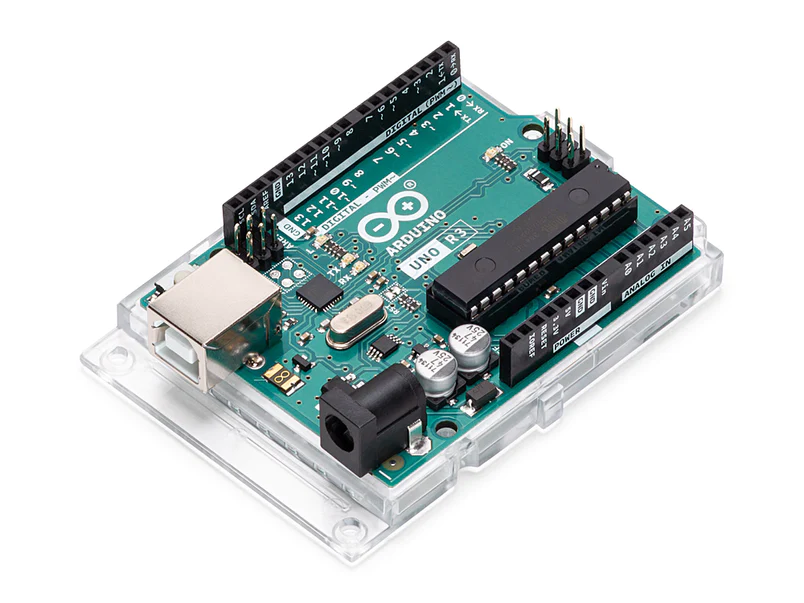
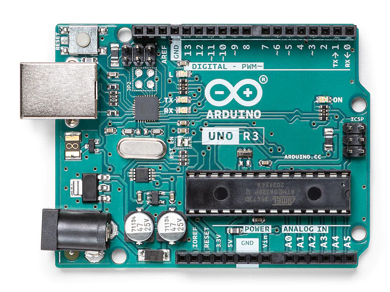
Arduino Uno is a microcontroller board based on the ATmega328P (datasheet). It has 14 digital input/output pins (of which 6 can be used as PWM outputs), 6 analog inputs, a 16 MHz ceramic resonator (CSTCE16M0V53-R0), a USB connection, a power jack, an ICSP header and a reset button. It contains everything needed to support the microcontroller; simply connect it to a computer with a USB cable or power it with a AC-to-DC adapter or battery to get started.. You can tinker with your Uno without worrying too much about doing something wrong, worst case scenario you can replace the chip for a few dollars and start over again.
"Uno" means one in Italian and was chosen to mark the release of Arduino Software (IDE) 1.0. The Uno board and version 1.0 of Arduino Software (IDE) were the reference versions of Arduino, now evolved to newer releases. The Uno board is the first in a series of USB Arduino boards, and the reference model for the Arduino platform; for an extensive list of current, past or outdated boards see the Arduino index of boards.
Related Boards
If you are interested in boards with similar functionality, at Arduino you can find:
Getting started
The Getting Started with Arduino Uno page contains all the information you need to configure your board, use the Arduino Software (IDE), and start tinkering with coding and electronics.
From the Tutorials section you can find examples from libraries and built-in sketches as well other useful information to expand your knowledge of the Arduino hardware and software.
Find inspiration for your Uno projects from our tutorial platform Project Hub.
Need Help?
Check the Arduino Forum for questions about the Arduino Language, or how to make your own Projects with Arduino. Need any help with your board please get in touch with the official Arduino User Support as explained in our Contact Us page.
Warranty
You can find here your board warranty information.
Tech specs
| Microcontroller | ATmega328P |
| Operating Voltage | 5V |
| Input Voltage (recommended) | 7-12V |
| Input Voltage (limit) | 6-20V |
| Digital I/O Pins | 14 (of which 6 provide PWM output) |
| PWM Digital I/O Pins | 6 |
| Analog Input Pins | 6 |
| DC Current per I/O Pin | 20 mA |
| DC Current for 3.3V Pin | 50 mA |
| Flash Memory | 32 KB (ATmega328P) of which 0.5 KB used by bootloader |
| SRAM | 2 KB (ATmega328P) |
| EEPROM | 1 KB (ATmega328P) |
| Clock Speed | 16 MHz |
| LED_BUILTIN | 13 |
| Length | 68.6 mm |
| Width | 53.4 mm |
| Weight | 25 g |
Conformities
Documentation
OSH: Schematics
Arduino Uno is open-source hardware! You can build your own board using the following files:
EAGLE FILES IN .ZIP SCHEMATICS IN .PDF BOARD SIZE IN .DXFDATASHEET IN .PDF
Pinout Diagram

Download the full pinout diagram as PDF here.
Interactive Board Viewer
Learn more
FAQs
Programming
The Arduino Uno can be programmed with the (Arduino Software (IDE)). Select "Arduino Uno from the Tools > Board menu (according to the microcontroller on your board). For details, see the reference and tutorials.
The ATmega328 on the Arduino Uno comes preprogrammed with a bootloader that allows you to upload new code to it without the use of an external hardware programmer. It communicates using the original STK500 protocol (reference, C header files).
You can also bypass the bootloader and program the microcontroller through the ICSP (In-Circuit Serial Programming) header using Arduino ISP or similar; see these instructions for details.
The ATmega16U2 (or 8U2 in the rev1 and rev2 boards) firmware source code is available in the Arduino repository. The ATmega16U2/8U2 is loaded with a DFU bootloader, which can be activated by:
- On Rev1 boards: connecting the solder jumper on the back of the board (near the map of Italy) and then resetting the 8U2.
- On Rev2 or later boards: there is a resistor that pulling the 8U2/16U2 HWB line to ground, making it easier to put into DFU mode.
You can then use Atmel's FLIP software (Windows) or the DFU programmer (Mac OS X and Linux) to load a new firmware. Or you can use the ISP header with an external programmer (overwriting the DFU bootloader). See this user-contributed tutorial for more information.
Warnings
The Arduino Uno has a resettable polyfuse that protects your computer's USB ports from shorts and overcurrent. Although most computers provide their own internal protection, the fuse provides an extra layer of protection. If more than 500 mA is applied to the USB port, the fuse will automatically break the connection until the short or overload is removed.
Differences with other boards
The Uno differs from all preceding boards in that it does not use the FTDI USB-to-serial driver chip. Instead, it features the Atmega16U2 (Atmega8U2 up to version R2) programmed as a USB-to-serial converter.
Power
The Arduino Uno board can be powered via the USB connection or with an external power supply. The power source is selected automatically.
External (non-USB) power can come either from an AC-to-DC adapter (wall-wart) or battery. The adapter can be connected by plugging a 2.1mm center-positive plug into the board's power jack. Leads from a battery can be inserted in the GND and Vin pin headers of the POWER connector.
The board can operate on an external supply from 6 to 20 volts. If supplied with less than 7V, however, the 5V pin may supply less than five volts and the board may become unstable. If using more than 12V, the voltage regulator may overheat and damage the board. The recommended range is 7 to 12 volts.
The power pins are as follows:
- Vin. The input voltage to the Arduino board when it's using an external power source (as opposed to 5 volts from the USB connection or other regulated power source). You can supply voltage through this pin, or, if supplying voltage via the power jack, access it through this pin.
- 5V.This pin outputs a regulated 5V from the regulator on the board. The board can be supplied with power either from the DC power jack (7 - 12V), the USB connector (5V), or the VIN pin of the board (7-12V). Supplying voltage via the 5V or 3.3V pins bypasses the regulator, and can damage your board. We don't advise it.
- 3V3. A 3.3 volt supply generated by the on-board regulator. Maximum current draw is 50 mA.
- GND. Ground pins.
- IOREF. This pin on the Arduino board provides the voltage reference with which the microcontroller operates. A properly configured shield can read the IOREF pin voltage and select the appropriate power source or enable voltage translators on the outputs to work with the 5V or 3.3V.
Memory
The ATmega328 has 32 KB (with 0.5 KB occupied by the bootloader). It also has 2 KB of SRAM and 1 KB of EEPROM (which can be read and written with the EEPROM library).
Input and Output
See the mapping between Arduino pins and ATmega328P ports. The mapping for the Atmega8, 168, and 328 is identical.
Each of the 14 digital pins on the Uno can be used as an input or output, using pinMode(),digitalWrite(), and digitalRead() functions. They operate at 5 volts. Each pin can provide or receive 20 mA as recommended operating condition and has an internal pull-up resistor (disconnected by default) of 20-50k ohm. A maximum of 40mA is the value that must not be exceeded on any I/O pin to avoid permanent damage to the microcontroller.
In addition, some pins have specialized functions:
- Serial: 0 (RX) and 1 (TX). Used to receive (RX) and transmit (TX) TTL serial data. These pins are connected to the corresponding pins of the ATmega8U2 USB-to-TTL Serial chip.
- External Interrupts: 2 and 3. These pins can be configured to trigger an interrupt on a low value, a rising or falling edge, or a change in value. See the attachInterrupt() function for details.
- PWM: 3, 5, 6, 9, 10, and 11. Provide 8-bit PWM output with the analogWrite() function.
- SPI: 10 (SS), 11 (MOSI), 12 (MISO), 13 (SCK). These pins support SPI communication using the SPI library.
- LED: 13. There is a built-in LED driven by digital pin 13. When the pin is HIGH value, the LED is on, when the pin is LOW, it's off.
- TWI: A4 or SDA pin and A5 or SCL pin. Support TWI communication using the Wire library.
The Uno has 6 analog inputs, labeled A0 through A5, each of which provide 10 bits of resolution (i.e. 1024 different values). By default they measure from ground to 5 volts, though is it possible to change the upper end of their range using the AREF pin and the analogReference() function. There are a couple of other pins on the board:
- AREF. Reference voltage for the analog inputs. Used with analogReference().
- Reset. Bring this line LOW to reset the microcontroller. Typically used to add a reset button to shields which block the one on the board.
Communication
The Arduino Uno has a number of facilities for communicating with a computer, another Arduino board, or other microcontrollers. The ATmega328 provides UART TTL (5V) serial communication, which is available on digital pins 0 (RX) and 1 (TX). An ATmega16U2 on the board channels this serial communication over USB and appears as a virtual com port to software on the computer. The 16U2 firmware uses the standard USB COM drivers, and no external driver is needed. However, on Windows, a .inf file is required. The Arduino Software (IDE) includes a serial monitor which allows simple textual data to be sent to and from the board. The RX and TX LEDs on the board will flash when data is being transmitted via the USB-to-serial chip and USB connection to the computer (but not for serial communication on pins 0 and 1).
A SoftwareSerial library allows serial communication on any of the Uno's digital pins.
The ATmega328 also supports I2C (TWI) and SPI communication. The Arduino Software (IDE) includes a Wire library to simplify use of the I2C bus; see the documentation for details. For SPI communication, use the SPI library.
Automatic (Software) Reset
Rather than requiring a physical press of the reset button before an upload, the Arduino Uno board is designed in a way that allows it to be reset by software running on a connected computer. One of the hardware flow control lines (DTR) of the ATmega8U2/16U2 is connected to the reset line of the ATmega328 via a 100 nanofarad capacitor. When this line is asserted (taken low), the reset line drops long enough to reset the chip. The Arduino Software (IDE) uses this capability to allow you to upload code by simply pressing the upload button in the interface toolbar. This means that the bootloader can have a shorter timeout, as the lowering of DTR can be well-coordinated with the start of the upload.
This setup has other implications. When the Uno is connected to either a computer running Mac OS X or Linux, it resets each time a connection is made to it from software (via USB). For the following half-second or so, the bootloader is running on the Uno. While it is programmed to ignore malformed data (i.e. anything besides an upload of new code), it will intercept the first few bytes of data sent to the board after a connection is opened. If a sketch running on the board receives one-time configuration or other data when it first starts, make sure that the software with which it communicates waits a second after opening the connection and before sending this data.
The Uno board contains a trace that can be cut to disable the auto-reset. The pads on either side of the trace can be soldered together to re-enable it. It's labeled "RESET-EN". You may also be able to disable the auto-reset by connecting a 110 ohm resistor from 5V to the reset line; see this forum thread for details.
Revisions
Revision 3 of the board has the following new features:
- 1.0 pinout: added SDA and SCL pins that are near to the AREF pin and two other new pins placed near to the RESET pin, the IOREF that allow the shields to adapt to the voltage provided from the board. In future, shields will be compatible with both the board that uses the AVR, which operates with 5V and with the Arduino Due that operates with 3.3V. The second one is a not connected pin, that is reserved for future purposes.
- Stronger RESET circuit.
- Atmega 16U2 replace the 8U2.
Arduino Uno Rev3的更多相关文章
- 基于Proteus仿真的Arduino学习(1)——Arduino Uno最小系统及LED的简单使用
一.前言: A.Arduino简介 Arduino是由一个欧洲开发团队于2005年冬季开发.其成员包括Massimo Banzi.David Cuartielles.Tom Igoe.Gianluc ...
- Arduino uno R3 ISP刷Rootloader for arduino pro mini
找了好久才发现的,好东西.介绍怎么使用uno对mini 刷Rootloader **SOLUTION** Reinstall the Arduino Pro Mini Bootloader using ...
- [Arduino] Arduino Uno R3 中文介绍
Arduino UNO是Arduino USB接口系列的最新版本,作为Arduino平台的参考标准模板.UNO的处理器核心是ATmega328,同时具有14路数字输入/输出口(其中6路可作为PWM输出 ...
- Arduino UNO仿真开发环境设置和仿真运行
一. Proteus仿真平台简介 Proteus软件是英国Labcenter electronics公司出版的EDA工具软件(该软件中国总代理为广州风标电子技术有限公司).它不仅具有其它EDA工具软件 ...
- Arduino UNO的原理图
Arduino UNO的原理图是开源的,所以可以从arduino网站上下载它: https://www.arduino.cc/en/Main/ArduinoBoardUno 原理图PDF: https ...
- 2.6 基于ARDUINO UNO+MC20的路径显示功能
需要准备的硬件 MC20开发板 1个 https://item.taobao.com/item.htm?id=562661881042 GSM/GPRS天线 1根 https://item.taoba ...
- 用 Arduino Uno 给 Arduino Mini(Pro)烧录程序
用 Arduino Uno 给 Arduino Mini(Pro)烧录程序 准备 Arduino Uno Arduino Mini(Pro) 杜邦线若干 接线 首先去掉 Arduino 上的芯片ATM ...
- Arduino UNO R3
Arduino 常见型号 当然还有 LilyPad,附图: 最常见的自然是UNO,最新版是第三版R3: 国内也有一些改进的板子.我用的是一般的板子,拿到货也只能默默了. 简介 The Uno is a ...
- 短信控制的 智能插头(sim900a arduino uno)
https://www.arduino.cn/thread-19432-1-2.html 1.所需工具:(1)arduino UNO,(2)sim900a模块,(3)单路继电器,(4)220v ac转 ...
- 如何使用Arduino UNO开发板编程ATtiny85
最近在Youtube上看了一个GreatScott制作的有关如何使用Attiny85的精彩教程,之后我购买了一片Attiny85 IC.但是,我花了很长时间尝试在它上面运行一个简单的LED闪烁的代码. ...
随机推荐
- uni-app简单通用Request网络请求 支持请求成功 失败回调
uni-app简单通用Request网络请求 支持请求成功 失败回调; 下载完整代码请访问uni-app插件市场地址:https://ext.dcloud.net.cn/plugin?id=12794 ...
- 逍遥自在学C语言 | 多级指针探秘
前言 多级指针在C语言中是一种特殊的指针类型,它可以指向其他指针的指针. 通过多级指针,我们可以间接地访问或修改存储在内存中的数据. 在本文中,我们将讨论多级指针的概念.使用方法.使用场景以及常见错误 ...
- 一次与 ChatGPT 的 .NET 面试问答
以常用问题来面试机器人,机器人是否能够合格 1. 您能描述一下您曾经在.NET项目中集成硬件设备的经历吗?这个过程是怎样的,您面临了哪些挑战? GPT 回答:当我在.NET项目中集成硬件设备时,我首先 ...
- c# 文件在线预览功能
using DocumentFormat.OpenXml.Packaging; using DocumentFormat.OpenXml.Wordprocessing; using DocumentF ...
- Linux内核笔记(三)内核编程语言和环境
学习概要: Linux内核使用的编程语言.目标文件格式.编译环境.内联汇编.语句表达式.寄存器变量.内联函数 c和汇编函数之间的相互调用机制Makefile文件的使用方法. as86汇编语言语法 汇编 ...
- 从0开发属于自己的nestjs框架的mini 版 —— ioc篇
如今,nodejs的框架也是层出不穷,偏向向底层的有 express.koa. Fastify,偏向于上层有阿里的 Egg.thinkjs .还有国外的 nestjs. 在这里我更喜欢 nestjs, ...
- Django: AssertionError: `HyperlinkedIdentityField` requires the request in the serializer context. Add `context={'request': request}` when instantiating the serializer.
错误翻译 AssertionError: ' HyperlinkedIdentityField '需要在序列化器上下文中请求.在实例化序列化器时添加' context={'request': requ ...
- QPushButton中常用的方法
常用方法如下所示: setCheckable():设置按钮是否已经被选中,如果设置为True,则表示按钮将保持已点击和释放状态. toggl():在按钮之间进行切换 setIcon():设置按钮上的图 ...
- 文心一言 VS 讯飞星火 VS chatgpt (70)-- 算法导论6.5 9题
九.请设计一个时间复杂度为 (n lgk)的算法,它能够将 k 个有序链表合并为一个有序链表,这里 n 是所有输入链表包含的总的元素个数.(提示:使用最小堆来完成 k 路归并. 文心一言: 要设计一个 ...
- UI获取元素的几种方式
通过浏览器驱动获取页面元素的8种方式. 定位方法: 通过webdriver对象的find_element方法 通过 id获取元素 el = driver.find_element(By.ID,'id' ...