
Half Wavelength Dipole Antenna
Reference :
1. wikipedia
The dipole antenna is the simplest and most widely used class of antenna.It consists of two identical conductive elements such as metal wires or rods, which are usually bilaterally symmetrical.Each side of the feedline to the transmitter or receiver is connected to one of the conductors.
Dipoles are resonant antennas, meaning that the elements serve as resonators, with standing waves of radio current flowing back and forth between their ends. So the length of the dipole elements is determined by the wavelength of the radio waves used. The most common form is the half-wave dipole, in which each of the two rod elements is approximately 1/4 wavelength long, so the whole antenna is a half-wavelength long. The radiation pattern of a vertical dipole is omnidirectional; it radiates equal power in allazimuthal directions perpendicular to the axis of the antenna. For a half-wave dipole the radiation is maximum, 2.15 dBi perpendicular to the antenna axis, falling monotonically with elevation angle to zero on the axis, off the ends of the antenna.
Several different variations of the dipole are also used, such as thefolded dipole, short dipole, cage dipole, bow-tie, and batwing antenna. Dipoles may be used as standalone antennas themselves, but they are also employed as feed antennas (driven elements) in many more complex antenna types, such as the Yagi antenna, parabolic antenna, reflective array, turnstile antenna, log periodic antenna, and phased array.
Dipole characteristics

1. Impedance
The feedpoint impedance of a dipole antenna is very sensitive to its electrical length. Therefore, a dipole will generally only perform optimally over a rather narrow bandwidth, beyond which its impedance will become a poor match for the transmitter or receiver (and transmission line). The real (resistive) and imaginary (reactive) components of that impedance, as a function of electrical length, are shown in the accompanying graph.

A true half-wave dipole is one half of the wavelength λ in length, where λ=c/f in free space. Such a dipole has a feedpoint impedance consisting of 73Ω resistance and +43Ω reactance, thus presenting a slightly inductive reactance. In order to cancel that reactance, and present a pure resistance to the feedline, the element is shortened by the factor k for a net length of:
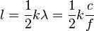
The adjustment factor k, in order for the reactance to be cancelled, depends on the diameter of the conductor. For thin wires (diameter= 0.00001 wavelengths), k is approximately 0.98; for thick conductors (diameter= 0.008 wavelengths), k drops to about 0.94. This is because the effect of antenna length on reactance is much greater for thinner conductors. For the same reason, antennas with thicker conductors have a wider operating bandwidth over which they attain an acceptablestanding wave ratio.

Dipole antennas of lengths approximately equal to any odd multiple of λ/2 are also resonant, presenting a small reactance (which can be cancelled by a small length adjustment). However these are rarely used. One size that is more practical though is a dipole with a length of 5/4 wavelengths. Not being close to 3/2 wavelengths, this antenna's impedance has a large (negative) reactance and can only be used with an impedance matching network (or "antenna tuner"). It is a desirable length because such an antenna has the highest gain for any dipole which isn't a great deal longer.
2. Radiation pattern and gain
Neglecting electrical inefficiency, the antenna gain is equal to the directive gain, which is 1.5 or 1.76 dBi for a short dipole, increasing to 1.64 or 2.15 dBi for a half-wave dipole. For a 5/4 wave dipole the gain further increases to about 5.2 dBi, making this length desirable for that reason even though the antenna is then off-resonance. Longer dipoles than that have radiation patterns that are multi-lobed, with poorer gain (unless they are much longer) even along the strongest lobe.

3. Feeding a dipole antenna
Ideally, a half-wave dipole should be fed using a balanced transmission line matching its typical 65 - 70Ω input impedance. Twin lead with a similar impedance is available but seldom used.
Many types of coaxial cable have a characteristic impedance of 75Ω, which would therefore be a good match for a half-wave dipole, however coax is an unbalanced transmission line (with one terminal at ground potential) whereas a dipole antenna presents a balanced input (both terminals have an equal but opposite voltage with respect to ground). When a balanced antenna is fed with a single-ended line, common mode currents can cause the coax line to radiate in addition to the antenna itself, distorting the radiation pattern and changing the impedance seen by the line. The dipole can be properly fed, and retain its expected characteristics, by using a balun in between the coaxial feedline and the antenna terminals. Connection of coax to a dipole antenna using a balun is plot below.


Another solution, especially for receiving antennas, is to use common 300 ohm twin lead in conjunction with a folded dipole. The folded dipole is similar to the simple half-wave dipole but with the feedpoint impedance multiplied by 4, thus closely matching that 300 ohm impedance. This is the most common household antenna for fixed FM broadcast band tuners, which usually include balanced 300 ohm antenna input terminals.
4. detailed calculation
The current distribution is that of a standing wave, approximately sinusoidal along the length of the dipole, with a node at each end and an antinode (peak current) at the center (feedpoint):


where k = 2π/λ and z runs from −L /2 to L /2.
In the far field, this produces a radiation pattern whose electric field is given by

A numerical integration of this integral over all solid angle, as we did for the short dipole, supplies a value for the radiation resistance:  Using the induced EMF method, the real part of the driving point impedance can also be written in terms of the cosine integral:

5 simlation result

Half Wavelength Dipole Antenna的更多相关文章
- Dipole Antenna : 2
Characteristics of dipole antenna. %% % characteristics of dipole antenna % author : Leon % email:ya ...
- dipole antenna simulation by FEKO
新建变量 建立模型 设置频率 馈电设置为wire port ,Edge 选中振子,从中心馈电. 设置输入信号 Mesh. run solver.在post feko中查看相关结果
- dipole antenna simulation by HFSS
工作频点为1GHz,新建工程,添加新设计,编辑添加下面的变量 建立天线模型,即两个金属圆柱.编辑完一个振子后,另一半可以用镜像命令产生参数如下设置 ,材料为PEC 两个圆柱间建立一个矩形片,连接两个圆 ...
- dipole antenna simulation by CST
CST偶极子天线仿真,半波振子天线 一.本文使用CST仿真频率为1GHz的偶极子天线,使用2013版本.仿真的步骤为 1.选择一个CST的天线工程模板 2.设置好默认的单位 3.设置背景的材料(空气腔 ...
- Radio Basics for RFID
Radio Basics for RFID The following is excerpted from Chapter 3: Radio Basics for UHF RFID from the ...
- 由浅入深学习PBR的原理和实现
目录 一. 前言 1.1 本文动机 1.2 PBR知识体系 1.3 本文内容及特点 二. 初阶:PBR基本认知和应用 2.1 PBR的基本介绍 2.1.1 PBR概念 2.1.2 与物理渲染的差别 2 ...
- RFID 读写器 Reader Writer Cloner
RFID读写器的工作原理 RFID的数据采集以读写器为主导,RFID读写器是一种通过无线通信,实现对标签识别和内存数据的读出和写入操作的装置. 读写器又称为阅读器或读头(Reader).查询器(Int ...
- 802.11 wireless 三
802.11 wireless 3watts,milliwatts,and Decibels瓦特(功率单位)的定义是1焦耳/秒微波炉1000瓦特,手机100-200毫瓦 decibels(分贝:比较能 ...
- POJ 3020 Antenna Placement
Antenna Placement Time Limit: 1000MS Memory Limit: 65536K Total Submissions: 5645 Accepted: 2825 Des ...
随机推荐
- Can you explain Lazy Loading?
Introduction Lazy loading is a concept where we delay the loading of the object until the point wher ...
- 启动Eclipse 弹出"Failed to load the JNI shared library jvm.dll"错误
启动Eclipse 弹出"Failed to load the JNI shared library jvm.dll"错误,如下 原因:eclipse的版本与jre或者jdk版本不 ...
- JavaScript 中有关数组对象的方法
JS 处理数组多种方法 js 中的数据类型分为两大类:原始类型和对象类型. 原始类型包括:数值.字符串.布尔值.null.undefined 对象类型包括:对象即是属性的集合,当然这里又两个特殊的对象 ...
- SharpGL学习笔记(十八) 解析3ds模型并显示
笔者设想的3D仿真中的元件,是不可能都是“画”出来的.这样就玩复杂了,应该把任务分包出去,让善于制作模型的软件来制作三维模型,我们只需要解析并且显示它即可. 3dsmax制作三维模型的方便,快捷,专业 ...
- Head First Design Patterns学习笔记-观察者模式
认识观察者模式 首先来看看报纸订阅的过程 1.报社的业务就是出版报纸 2.向某家报社订阅报纸,只要他们有新报纸出版,就会送过来,只要你是他们的订户 3.当你不想再看报纸的时候,取消订阅,他们就不会再送 ...
- android 浏览器开发实例
android app需要通过手机显示网页信息还是比较常用的,比如我最近业余开发的 抢商铺游戏,需要对游戏规则做说明,规则会比较多,而且要经常变动,就想到用网页来展示,更新起来方便,不像应用,一旦发布 ...
- 【读书笔记】iOS-安全地传输用户密码的方法
正确做法:事先生成一对用于加密的公私钥,客户端在登录时,使用公钥将用户的密码加密后,将密文传输到服务器.服务器使用私钥将密码解密,然后加盐之后多次请求MD5,之后再和服务器原来存储的用同样方法处理过的 ...
- Struts2(十四)拦截器实现权限管理
一.认识拦截器 拦截器也是一个类 拦截器可以在Action被调用之前和之后执行代码 框架很多核心功能是拦截器实现的 拦截器的特点: 拦截器自由组合,增强了灵活性.扩展性.有利于系统解耦 拦截器可以拦截 ...
- iOS设计模式-单例模式
(一)什么是单例模式(Singleton) 单例模式:保证一个类仅有一个实例,并提供一个访问它的全局访问点 *最初的定义是在<设计模式>(Addison-Wesley)中 解读 1> ...
- Silverlight项目笔记1:UI控件与布局、MVVM、数据绑定、await/async、Linq查询、WCF RIA Services、序列化、委托与事件
最近从技术支持转到开发岗,做Silverlight部分的开发,用的Prism+MVVM,框架由同事搭好,目前做的主要是功能实现,用到了一些东西,侧重于如何使用,总结如下 1.UI控件与布局 常用的主要 ...