STM32 Controller area network (bxCAN) Identifier filtering
Identifier filtering
In the CAN protocol the identifier of a message is not associated with the address of a node but related to the content of the message.
Consequently a transmitter broadcasts its message to all receivers.
On message reception a receiver node decides - depending on the identifier value - whether the software needs the message or not.
If the message is needed, it is copied into the SRAM.
If not, the message must be discarded without intervention by the software.
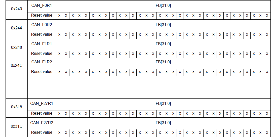
To fulfill this requirement, the bxCAN Controller provides 28 configurable and scalable filter banks (27-0) to the application.
In other devices the bxCAN Controller provides 14 configurable and scalable filter banks (13-0) to the application
in order to receive only the messages the software needs.
This hardware filtering saves CPU resources which would be otherwise needed to perform filtering by software.
Each filter bank x consists of two 32-bit registers, CAN_FxR0 and CAN_FxR1. = 2 * 28 = 56 Registers

Scalable width
To optimize and adapt the filters to the application needs, each filter bank can be scaled independently.
Depending on the filter scale a filter bank provides:
One 32-bit filter for the STDID[10:0], EXTID[17:0], IDE and RTR bits.
Two 16-bit filters for the STDID[10:0], RTR, IDE and EXTID[17:15] bits.
Furthermore, the filters can be configured in mask mode or in identifier list mode.
Mask mode
In mask mode the identifier registers are associated with mask registers specifying
which bits of the identifier are handled as must match or as dont care.
Each bit of the register specifies whether the bit of the associated identifier register
must match with the corresponding bit of the expected identifier or not.
0: Dont care, the bit is not used for the comparison --- Don't Care
1: Must match, the bit of the incoming identifier must have the same level
has specified in the corresponding identifier register of the filter -- Do Care.
Identifier list mode
In identifier list mode, the mask registers are used as identifier registers.
Thus instead of defining an identifier and a mask, two identifiers are specified,
doubling the number of single identifiers.
All bits of the incoming identifier must match the bits specified in the filter registers.
Each bit of the register specifies the level of the corresponding bit of the expected identifier.
0: Dominant bit is expected
1: Recessive bit is expected
Filter bank scale and mode configuration
The filter banks are configured by means of the corresponding CAN_FMR register.
To configure a filter bank it must be deactivated by clearing the FACT bit in the CAN_FAR register.
The filter scale is configured by means of the corresponding FSCx bit in the CAN_FS1R register, refer to Figure 342.
The identifier list or identifier mask mode for the corresponding Mask/Identifier registers is configured
by means of the FBMx bits in the CAN_FMR register.
To filter a group of identifiers, configure the Mask/Identifier registers in mask mode.
To select single identifiers, configure the Mask/Identifier registers in identifier list mode.
Filters not used by the application should be left deactivated.
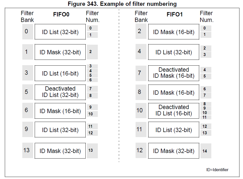
Each filter within a filter bank is numbered (called the Filter Number)
from 0 to a maximum dependent on the mode and the scale of each of the filter banks.
Concerning the filter configuration, refer to Figure 342.
Filter match index
Once a message has been received in the FIFO it is available to the application.
Typically, application data is copied into SRAM locations.
To copy the data to the right location the application has to identify the data by means of the identifier.
To avoid this, and to ease the access to the SRAM locations, the CAN controller provides a Filter Match Index.
This index is stored in the mailbox together with the message according to the filter priority rules.
Thus each received message has its associated filter match index.
The Filter Match index can be used in two ways:
Compare the Filter Match index with a list of expected values.
Use the Filter Match Index as an index on an array to access the data destination location.
For nonmasked filters, the software no longer has to compare the identifier.
If the filter is masked the software reduces the comparison to the masked bits only.
The index value of the filter number does not take into account the activation state of the
filter banks. In addition, two independent numbering schemes are used, one for each FIFO.
Refer to Figure 343 for an example.
Filter priority rules
Depending on the filter combination it may occur that an identifier passes successfully through several filters.
In this case the filter match value stored in the receive mailbox is chosen according to the following priority rules:
A 32-bit filter takes priority over a 16-bit filter.
For filters of equal scale, priority is given to the Identifier List mode over the Identifier Mask mode
For filters of equal scale and mode, priority is given by the filter number (the lower the number, the higher the priority).

The example above shows the filtering principle of the bxCAN. On reception of a message, the identifier is compared first with the filters configured in identifier list mode.
If there is a match, the message is stored in the associated FIFO and the index of the matching filter is stored in the Filter Match Index.
As shown in the example, the identifier matches with Identifier #2 thus the message content and FMI 2 is stored in the FIFO.
If there is no match, the incoming identifier is then compared with the filters configured in mask mode.
If the identifier does not match any of the identifiers configured in the filters, the message is discarded by hardware without disturbing the software.
STM32 Controller area network (bxCAN) Identifier filtering的更多相关文章
- 再谈STM32的CAN过滤器-bxCAN的过滤器的4种工作模式以及使用方法总结
1. 前言 bxCAN是STM32系列最稳定的IP核之一,无论有哪个新型号出来,这个IP核基本未变,可见这个IP核的设计是相当成熟的.本文所讲述的内容属于这个IP核的一部分,掌握了本文所讲内容,就可以 ...
- Real-time storage area network
A cluster of computing systems is provided with guaranteed real-time access to data storage in a sto ...
- 存储区域网络(Storage Area Network,简称SAN)
存储区域网络(Storage Area Network,简称SAN)采用网状通道(Fibre Channel ,简称FC,区别与Fiber Channel光纤通道)技术,通过FC交换机连接存储阵列和服 ...
- mvc action controller area
获取控制器名称: ViewContext.RouteData.Values["controller"].ToString(); 获取Action名称: ViewContext.Ro ...
- linux 下使用 tc 模拟网络延迟和丢包-使用 linux 模拟广域网延迟 - Emulating wide area network delays with Linux
tc 是linux 内置的命令:使用man pages 查看 我们看到,其功能为 show / manipulate traffic control settings,可对操作系统进行流量控制: ne ...
- HDU 2125 Local area network
简单DP,N×M的网格其中有一条边坏掉了,问从起点到终点的放法数 有两种方法,一种是DP很好理解 //#define LOCAL #include <cstdio> #include &l ...
- STM32(12)——CAN
简介: CAN是Controller Area Network,是 ISO 国际标准化的串行通信协议. CAN 控制器根据两根线上的电位差来判断总线电平.总线电平分为显性电平和隐性电平,二者必居其一 ...
- stm32之CAN总线基础
can总线协议概述: CAN是Controller Area Network的缩写,由德国博世公司开发:CAN通过ISO11891以及ISO11519进行了标准化: CAN总线的特点: 1.多 ...
- CAN通信(STM32)
1.CAN是控制器局域网络(Controller Area Network, CAN)的简称 (理论知识不做讲解了,太多了) 2.芯片选用:TJA1050 差分信号输入, 这里的显性电平CANH和CA ...
随机推荐
- shell 判断为空打印
判断参数是否为空-空退出并打印null #!/bin/sh echo $ name=${:?"null"} echo $name
- C# p2p UDP穿越NAT,UDP打洞源码
思路如下(参照源代码): 1. frmServer启动两个网络侦听,主连接侦听,协助打洞的侦听. 2. frmClientA和frmClientB分别与frmServer的主连接保持联系. 3. 当f ...
- (F - 超级英雄Hero HYSBZ - 1191 )匈牙利算法
题目链接:https://cn.vjudge.net/contest/281037#problem/F 题目大意:中文题目 具体思路:可以看成二分图匹配,寻找最大匹配就可以了,注意当某一个匹配不到的时 ...
- Centos6.5下升级Python版本
Cenos6.5升级Python2.6到2.7 1.下载源码包 wget https://www.python.org/ftp/python/2.7.12/Python-2.7.12.tgz 2.进行 ...
- 解决getJSON跨域登录Session丢失的问题
最近在做项目中发现,我用下面的代码异步请求到login.ashx: var memberUrl = rooturl + 'member.ashx?r=' + Math.random() + '& ...
- Windows下安装Python及Eclipse中配置PyDev插件
最近开始接触Python,鉴于之前安装Java的教训,决定这次边安装Python,边写下历程,供日后反复使用. 在Python官网http://www.python.org/下载Python版本,鉴于 ...
- 解决spring boot JavaMailSender部分收件人错误导致发送失败的问题
使用spring boot通常使用spring-boot-starter-mail进行邮件的发送.当进行邮件群发的话,如果一个收件人的地址错误,会导致所有邮件都发送失败.因此我们需要在邮件发送失败的时 ...
- intellij 出现“Usage of API documented as @since 1.8+”的解决办法
intellij 出现“Usage of API documented as @since 1.8+”的解决办法 Usage of API documented as @since 1.8+ This ...
- InnoDB逻辑存储结构
从InnoDB存储引擎的逻辑存储结构看,所有数据都被逻辑地存放在一个空间中,称之为表空间(tablespace).表空间又由段(segment).区(extent).页(page)组成.页在一些文档中 ...
- ResultCode 自定义错误状态码
public class ResultCode { // 成功状态码 public static final int SUCCESS = 1; // -------------------失败状态码- ...