
How determine the RC time constant in PWM DAC low-pass filter?
how determine the RC time constant
in PWM digital to analog low-pass filter?
I 'm looking for the best RC time constant and its reason in a PWM to convert digital signal to analog based
on duty-cycle and frequency and other parameters.
PWM frequency is 10 kHz.
The best RC is infinite, then you have a perfectly ripple-less DC output.
Problem is that it also takes forever to respond to changes in the duty cycle.
So it's always a tradeoff. A first-order RC filter has a cutoff frequency of

and a roll-off of 6 dB/octave = 20 dB/decade.
The graph shows the frequency characteristic for a
0.1 Hz (blue), a 1 Hz (purple) and a 10 Hz (the other color) cutoff frequency.
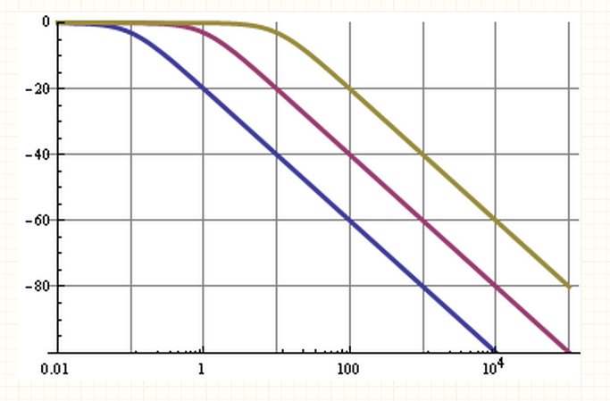
So we can see that for the 0.1 Hz filter the 10 kHz fundamental of the PWM signal is suppressed by 100 dB, that's not bad;
this will give very low ripple. But!
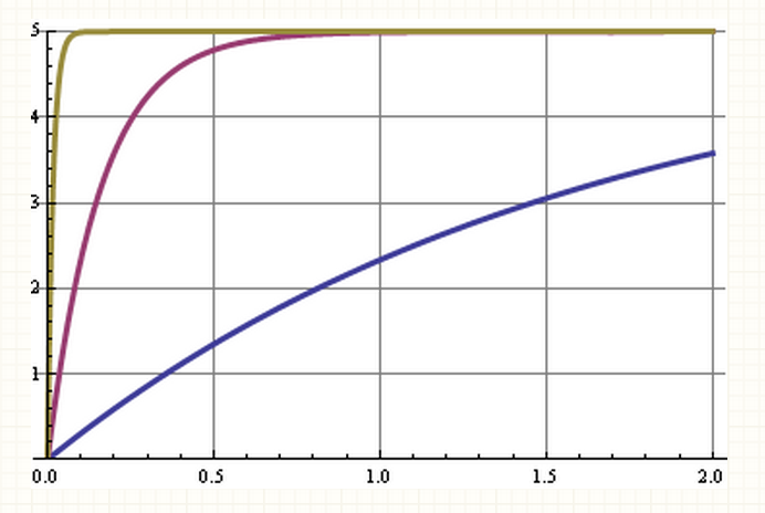
This graph shows the step response for the three cutoff frequencies.
A change in duty cycle is a step in the DC level, and some shifts in the harmonics of the 10 kHz signal.
The curve with the best 10 kHz suppression is the slowest to respond, the x-axis is seconds.
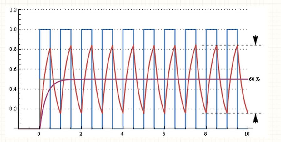
This graph shows the response of a 30 µs RC time (cutoff frequency 5 kHz) for a 50 % duty cycle 10 kHz signal.
There's an enormous ripple, but it responds to the change from 0 % duty cycle in 2 periods, or 200 µs.
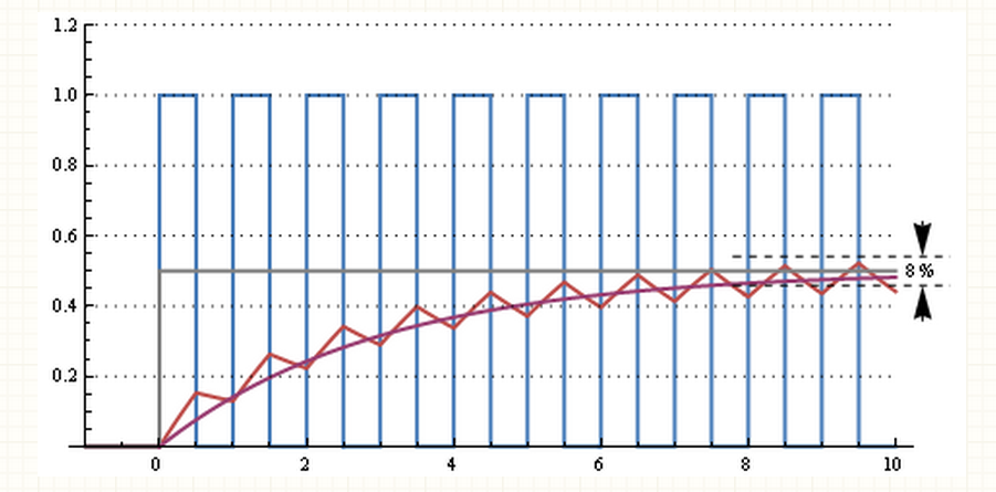
This one is a 300 µs RC time (cutoff frequency 500 Hz).
Still some ripple, but going from 0 % to 50 % duty cycle takes about 10 periods, or 1 ms.
Further increasing RC to milliseconds will decrease ripple further and increase reaction time.
It all depends on how much ripple you can afford and how fast you want the filter to react to duty cycle changes.
This web page calculates that for R = 16 kΩ and C = 1 µF
we have a cutoff frequency of 10 Hz,
a settling time to 90 % of 37 ms for a peak-to-peak ripple of 8 mV at 5 V maximum.
You can improve your filter by going to higher orders:

The blue curve was or simple RC filter with a 20 dB/decade roll-off.
A second order filter (purple) has a 40 dB/decade roll-off,
so for the same cutoff frequency will have 120 dB suppression at 10 kHz instead of 60 dB.
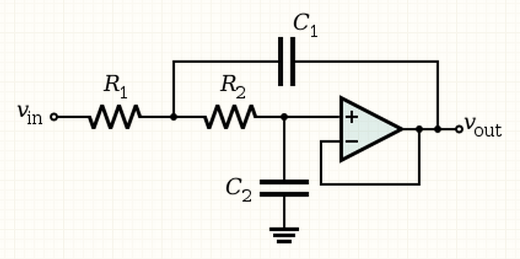
These graphs are pretty ideal and can be best attained with active filters, like a Sallen-Key.
Equations
Peak-to-peak ripple voltage for a first order RC filter as a function of PWM frequency and RC time constant:

"d" is the duty cycle, 0..1.
Ripple is the largest for d = 0.5
Step response to 99 % of end value is 5 x RC.
Cutoff frequency for the Sallen-Key filter:

For a Butterworth filter (maximum flat):
R1 =R2, C1 = C2
Fc = 1 / ( 2 * pi * sqrt( R1 * R1 * C1 * C1 ) ) = 1 / ( 2 * pi * R1 * C1 ) ) = 1/ ( 6.3 * ( R1 * C1 ) ) = 0.16 / ( R1 * C1 )
As Steven said, it's a tradeoff between attenuating the PWM frequency versus response time.
This is why any such decision has to start with a spec of what you want from the resulting analog signal.
What signal to noise ratio does it need to be, or at least how much noise at the PWM frequency can you tolerate?
How fast does it have to settle to the noise floor level?
Or conversely, what is the upper frequency you care about?
Note that it may not be possible to meet a particular set of criteria with a particular PWM output.
Let's say you wanted good quality voice output.
We'll say that's up to 8 kHz and 60 dB signal to noise.
That isn't going to happen with any reasonably tractable analog filter with 20 kHz PWM,
and certainly not with anything as simple as a single R and C.
As a example, let's work backwards and see what the PWM characterstics would have to be
to support the above voice example with a single R,C filter.
We've already said the -3 dB rolloff frequency is 8 kHz,
so that's what we set the R and C to.
The rolloff frequency of a single R,C filter is:

When R is in Ohms, C in Farads, then F is in Hertz.
It should be obvious this equation can be rearranged to solve for any of R, C, or F given the other two.
I keep 1/(2 π) = .15915 always in a register in my calculator
because this computation comes up regularly in electronics.
Then I simply divide that by two of R, C, or F to get the third.
We have two degrees of freedom and the above equation only nails down one of them.
The other can be thought of as the impedance you want the resulting signal to have.
Let's shoot for around 10 kΩ, which is what we'll make R just to see what C comes out to:

That's basically the standard capacitor value of 2 nF, so we'll just go with that.
If it hadn't come out to a common value, we'd have picked a near one then gone back and adjusted R accordingly.
Resistors are available in much finer variations and at higher tolerances than ordinary capacitors,
so you usually find a close capacitor value, then let that drive the exact resistor value.
So we've settled on R = 10 kΩ and C = 2 nF.
Note that this has come from the 8 kHz upper frequency requirement.
We have no more choices to make, so the settling time and signal to noise ratio will be what it will be.
All we can do now is determine whether it will be good enough, or conversely,
what PWM characteristics would be necessary to support the output signal specs.
Since the spec was a signal to noise ratio of 60 dB,
that means the noise must be less than 1 part in 1000 of the voltage,
which means the PWM frequency must be attenuated by that much.
A single R,C filter attenuates inversely proportional to frequency after the rolloff frequency.
This is a approximation that breaks near the rolloff frequency and below,
but it's good enough in most cases after a octave or two past the rollof frequency.
In other words, 16 kHz will be attenuated by 2 with some error, 32 kHz by 4 with less error,
and after that you can pretty much just divide the frequency of interest by the rolloff frequency to get attenuation.
We want the PWM frequency to be attenuated by 1000, which means it needs to be 8 MHz or higher.
That's high but doable with some processors.
For example, some of the PIC 24H and dsPIC line
have a special "power supply control" PWM module that operate at just under 1 GHz.
Now let's look at the PWM resolution.
Again, this is driven by the 60 dB signal to noise spec, which we know already means 1:1000.
That would require a PWM resolution of at least 999 (you always get one more output level than the PWM resolution).
That means the internal PWM slice clock needs to run 999 times the 8 MHz PWM output frequency, or basically 8 GHz.
Not gonna happen with reasonably available off the shelf parts.
However, there is a way to get around these limitations, and that is to use more than just a single R,C filter.
When I want a nice analog signal, I usually use two or three of them in succession.
Let's see how using three successive R,C filters changes things.
We originally said our upper frequency of interest was 8 kHz,
which implies we can tolerate that being 3 dB down unless we say otherwise.
A single R,C filter will attenuate by 3 dB at the rolloff frequency, so we put it at right at 8 kHz.
We can't have three filters at 8 kHz since they would attenuate by 9 dB there combined.
So, we move the filters out by the number of poles (separate R,C filters in this case).
The three R,C filters (three poles) are therefore at 24 kHz.
It seems like we lost ground doing this, but the big advantage is
that the frequencies above that are now attenuated by the ratio cubed instead of just the ratio as with a single pole.
Again we want the PWM frequency to be attenuated by 1000, which is 10^3,
so we only need to be 10x beyond the filter rolloff frequencies which means 240 kHz is high enough.
That's a big difference from 8 MHz.
Now the internal PWM clock or PWM slice frequency only needs to be 240 MHz.
That's still high but attainable.
Hopefully this has given you some insight into the issues.
If you provide concrete specs we can work thru specific values for your case.
It's possible to improve performance over a single RC by using cascaded RC stages.
One cannot get as good performance in a pure multi-stage RC passive filter as can be obtained from active filters,
but performance may nonetheless be better than with a single stage.
Unfortunately, I don't know any particular good methods for computing optimal RC values.
Another thing to note is that while pulse-width modulation is the most common form of duty-cycle modulation, it is not the only one.
One simple approach which can be very useful in cases where the target output voltage won't be changing too often,
and where the output is more likely to be near the center of the range than at the edges,
is to generate a set of signals by computing (current counter value "and not" previous counter value),
and ANDing that signal with the bits of desired data value,
in reverse order (so that the MSB of the data value gets AND'ed with the xor of the present counter LSB and the previous one).
Using such an approach with e.g. six-bit duty cycle modulation would mean a 32/64 duty cycle wave
will be represented by a frequency of half the PWM clock, rather than square wave with a frequency 1/64 of the PWM clock.
A 33/64 duty cycle would be represented mostly by a frequency of half the PWM clock, but with some extra high pulses thrown in.
Here's a demo of what I'm talking about.

All great answers given so far, well written and relevant,
but often the best answer needs a better question.
When you consider "best amount of RC?", what assumptions need to be considered for any design;
What is impedance of filter relative to impedance of source and load?
If not critical, choose R in between source and load. But say if CMOS driver is a value 10~100 Ω and say load is 100KΩ, but you want 0.3% accuracy on DC loss, then choose R << 0.3% of R-load, or as I call it "impedance ratio method" for loading considerations so here R < 0.003 * 1e5 = 300Ω. This choice of R is not critical, but you must take care not to load filter, so you may choose by impedance ratios for quick calculation on DC loss and AC rejection.
- if you wanted noise @ 10KHz PWM to be <1% of source, then choose impedance of Zc(f) to be <1% of R for series RC LPF.
- if you wanted ripple >80dB down on all harmonics above 0.5 MHz for interference reasons, say on AM radio or FCC/CE EMC tests, again look at impedance ratio of cap including ESR relative to R estimate a value of C then choose slightly bigger with margin for temp. tolerance and consider how much margin you need. You know that 1st order filters have a slope of 20dB/decade and then you can decide if 1st order filter is sufficient. Cascading RC filters must consider the loading effects on each stage. LC filters cost more and active filter may be needed.
Assuming you know impedance of a capacitor impedance ratio criteria is a simple solution. Otherwise to find an impedance in the middle of source and load consider one method Rf = √(Rs*Rl), where Rf is filter RC value for source, Rs and load Rl as one method for middle range.
The nice thing about design, is depending on your criteria, there are often multiple "best" answers for RC value. :)
How determine the RC time constant in PWM DAC low-pass filter?的更多相关文章
- PWM DAC Low Pass Filtering
[TI博客大赛][原创]LM3S811之基于PWM的DAC http://bbs.ednchina.com/BLOG_ARTICLE_3005301.HTM http://www.fpga4fun.c ...
- PWM DAC vs. Standalone
http://analogtalk.com/?p=534 http://analogtalk.com/?p=551 Posted by AnalogAdvocate on April 09, 2010 ...
- 【STM32】PWM DAC基本原理(实验:PWM实现DAC)
虽然STM32F103ZET6具有内部DAC,但是也仅仅只有两条DAC通道,并且STM32还有其他的很多型号是没有DAC的.通常情况下,采用专用的D/A芯片来实现,但是这样就会带来成本的增加. 不过S ...
- MCU PWM DAC OP Voltage Output
- how to generate an analog output from a in-built pwm of Atmega 32AVR microcontrloller?
how to generate an analog output from a in-built pwm of Atmega 32AVR microcontrloller? you need a re ...
- RFID 读写器 Reader Writer Cloner
RFID读写器的工作原理 RFID的数据采集以读写器为主导,RFID读写器是一种通过无线通信,实现对标签识别和内存数据的读出和写入操作的装置. 读写器又称为阅读器或读头(Reader).查询器(Int ...
- RFID Reader 线路图收集
This 125 kHz RFID reader http://www.serasidis.gr/circuits/RFID_reader/125kHz_RFID_reader.htm http:// ...
- DAC Essentials
http://e2e.ti.com/blogs_/b/analogwire/archive/tags/DAC%2bEssentials DAC Essentials: A new blog serie ...
- PID DC/DC Converter Controller Using a PICmicro Microcontroller
http://www.microchip.com/stellent/idcplg?IdcService=SS_GET_PAGE&nodeId=1824&appnote=en011794 ...
随机推荐
- PYTHON-面向对象 继承 派生
1. 什么是继承 继承是一种新建类的方式,新建的类称之为子类/派生类,被继承的类称之为父类/基类/超类 继承有3个特点: 1. 子类可以遗传/重用父类的属性(解决类与类之间代码冗余的问题) 2. 在p ...
- 采用busybox 代替android 自带的shell
折腾了几天,被Android那点儿少得可怜的shell命令折磨的死去活来,终于下定了革命的决心.看一下怎么把渺小的toolbox替换成伟大的busybox吧.先大致描述一下Android系统中的she ...
- wpf Assembly.LoadFile dll GetType 反射 抛异常 不具有由 URI 识别的资源。
public static void LoadViewFromUri(this Window window, string baseUri) { try { var resourceLocater = ...
- 【C++ Primer | 15】构造函数与拷贝控制
合成拷贝控制与继承 #include <iostream> using namespace std; class Base { public: Base() { cout << ...
- JS高级 - 面向对象5(继承,引用)
<script type="text/javascript"> //------------------Person类 //(Person)的构造函数 function ...
- Redis的优势和特点
Redis的特点: 内存数据库,速度快,也支持数据的持久化,可以将内存中的数据保存在磁盘中,重启的时候可以再次加载进行使用. Redis不仅仅支持简单的key-value类型的数据,同时还提供list ...
- springbank 开发日志 阅读spring mvc的源代码真是受益良多
决定模仿spring mvc的dispatcher->handlerMapping(return executorChain)->handler.execute 这样的流程之后,就开始看s ...
- hihocoder 1343 : Stable Members【拓扑排序】
hihocoder #1343:题目 解释:一个学习小组,一共有N个学员,一个主管.每个学员都有自己的导师(一个或者多个),导师可以是其他学员也可以是主管.每周学员都要把自己的学习报告和收到的报告提交 ...
- 在Ubuntu下解决 adb devices :???????????? no permissions 方法
http://sdvdxl.blog.51cto.com/3845763/1126539 MODE表示读取模式,0666表示任何人都可以访问. 最后 adb devices查看
- js中setInterval和setTimeout区别和用法
setTimeout setTimeout() //- 在指定时间后执行代码clearTimeout() //- 取消 setTimeout(),clearTimeout()方法的参数必须是由setT ...