STM32 串口USART DMA方式发送接收数据
硬件:stm32f103cbt6
软件:STM32F10x_StdPeriph_Lib_V3.5.0
DMA,直接内存存取,类似用它的双手释放CPU的灵魂,所以,本文通过USART3进行串口收发,接受使用DMA的方式,无需CPU进行干预,当接受完成之后,数据可以直接从内存的缓冲区读取,从而减少了CPU的压力。
具体的代码实现如下:
usart_driver.h封装了接口,数据接收回调函数类型,基本数据结构等;usart_driver.c函数原型实现,中断服务函数实现等;
拷贝这两个文件即可,可以根据目录下的参考用例,进行初始化。
头文件
usart_driver.h已经声明了外部函数可能用到的接口;
USART3_DR的地址
因为USART3接收到数据会存在DR寄存器中,而DMA控制器则负责将该寄存器中的内容一一搬运到内存的缓冲区中(比如你定义的某个数组中),所以这里需要告诉DMA控制去哪里搬运,因此需要设置USART3_DR的总线地址。
USART3的基址如下图所示;
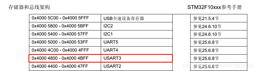
DR寄存器的偏移地址如下图所示;
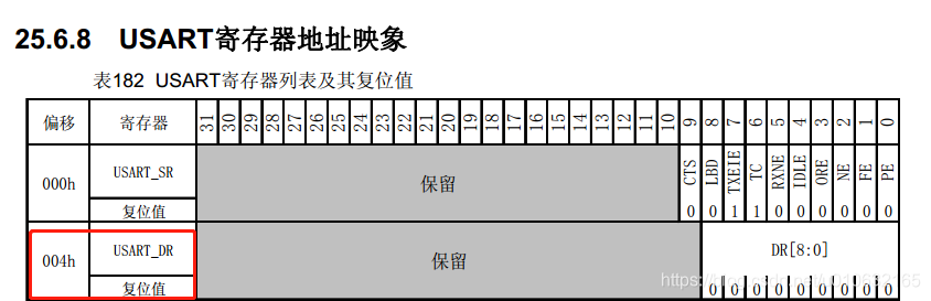
所以最终地址为:0x40004800 + 0x004
#define USART_DR_Base 0x40004804
DMA的通道
因为有很多外设都可以使用DMA,比如ADC,I2C,SPI等等,所以,不同的外设就要选择属于自己的DMA通道,查找参考手册;
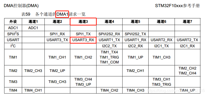
因此USART3_RX在这里会使用DMA1的通道3,这都是硬件上已经预先分配好的,我们需要遵循这个规则。
所以在代码中我们做出相应的定义;如下所示;
#define USART_Rx_DMA_Channel DMA1_Channel3
DMA的中断
DMA支持三种中断:传输过半,传输完成,传输出错;
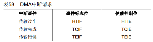
因此在使用是相当安全也相当灵活,而本文只是用了传输完成中断;如下定义了,传输完成中断的标志位,DMA1_FLAG_TC3也就对应了图中的TCIF;
#define USART_Rx_DMA_FLAG DMA1_FLAG_TC3
USART接收回调函数
在STM32的HAL中封装了大量外设的回调函数,使用起来十分方便,但是标准库中则没有这样的做法,但是这里我们可以自己实现,rx_cbk就是回调,即串口数据接收完成就会执行已经注册的回调函数;
typedef void (*rx_cbk)(void* args);
通过使用接口usart_set_rx_cbk进行回调函数的注册,pargs为将传递的参数指针;
void usart_set_rx_cbk(uart_mod_t *pmod, rx_cbk pfunc,void *pargs);
头文件源码
#ifndef USART_DRIVER_H

#define USART_DRIVER_H

#include <stdio.h>

#include <stdint.h>

/* Private function prototypes -----------------------------------------------*/

#define USE_MICROLIB_USART 1

#if USE_MICROLIB_USART

#ifdef __GNUC__

/* With GCC/RAISONANCE, small printf (option LD Linker->Libraries->Small printf

   set to 'Yes') calls __io_putchar() */

#define PUTCHAR_PROTOTYPE int __io_putchar(int ch)

#else

#define PUTCHAR_PROTOTYPE int fputc(int ch, FILE *f)

//#define GETCHAR_PROTOTYPE int fgetc(FILE *f)

#endif /* __GNUC__ */

extern PUTCHAR_PROTOTYPE;

#else

#endif

//default 8N1

#define COM_PORT	USART3

#define TX_PIN		GPIO_Pin_10

#define RX_PIN		GPIO_Pin_11

#define BAUDRATE	115200

#define IRQ_UART_PRE	3

#define IRQ_UART_SUB	3

#define USART_Rx_DMA_Channel    DMA1_Channel3

#define USART_Rx_DMA_FLAG       DMA1_FLAG_TC3

#define USART_DR_Base           0x40004804

#define USART_BUF_SIZE			((uint16_t)16)

typedef void (*rx_cbk)(void* args);

struct uart_mod {

	uint8_t rx_buf[USART_BUF_SIZE];

	uint8_t rx_dat_len;

	uint8_t head;

	uint8_t tail;

	void (*init)(void);

	void *pargs;

	rx_cbk pfunc_rx_cbk;

};

typedef struct uart_mod uart_mod_t;

extern  uart_mod_t user_uart_mod;

void usart_init(void);

void usart_set_rx_cbk(uart_mod_t *pmod, rx_cbk pfunc,void *pargs);

void usart_send_char(char ch);

void usart_test_echo(void);

uint8_t usart_recv_char(void);

int usart_printf(const char *fmt, ...);

//extern GETCHAR_PROTOTYPE;

#endif
DMA的基本配置
串口接收DMA的配置在函数dma_init中;
static void dma_init(void)
已经定义了数据缓冲区,如下:
uint8_t RxBuffer[USART_BUF_SIZE] = { 0 };
因此需要在DMA的配置中设置USART_DR的地址,和数据缓冲区的地址,以及两者的大小;
还有就是数据流向;
- 寄存器流向内存;
- 内存流向寄存器;
这个需要搞清楚;相关配置如下所示;
	DMA_InitStructure.DMA_PeripheralBaseAddr = USART_DR_Base;

	DMA_InitStructure.DMA_MemoryBaseAddr = (uint32_t)RxBuffer;

	DMA_InitStructure.DMA_BufferSize = USART_BUF_SIZE;

	DMA_InitStructure.DMA_DIR = DMA_DIR_PeripheralSRC;
注意:
DMA_DIR_PeripheralSRC表示,外设作为源地址,数据是从外设寄存器流向内存,即DMA会把数据从地址USART_DR_Base搬运到RxBuffer去。
如果这个地方搞错,会导致RxBuffer始终没有你想要的数据。
环形队列接收数据
线性缓冲区会因为缓冲器接收数据已满导致无法继续接收的问题;而环形队列进行接收的话,会自动进行覆盖,这样一来,在读取数据的时候,也要配置一个环形队列进行数据处理,下面的配置是把DMA配置为循环模式;
DMA_InitStructure.DMA_Mode = DMA_Mode_Circular;
在结构体user_uart_mod中,则用两个变量分别指向队首head和队尾tail;
具体数据的读取在函数USART3_IRQHandler中,会把数据从内存的RxBuffer读取到结构体user_uart_mod的成员变量rx_buf中;
最终调用回调函数。
函数原型
usart_driver.c
#include <stdio.h>

#include <stdarg.h>

#include "stm32f10x_usart.h"

#include "usart_driver.h"

uint8_t RxBuffer[USART_BUF_SIZE] = { 0 };

uart_mod_t user_uart_mod = {

	.rx_dat_len = 0,

	.head = 0,

	.tail = 0,

	.pfunc_rx_cbk = NULL,

	.pargs = NULL

};

static USART_InitTypeDef USART_InitStructure;

static void rcc_init(void){

	RCC_AHBPeriphClockCmd(RCC_AHBPeriph_DMA1, ENABLE);

	/* Enable GPIO clock */

	RCC_APB2PeriphClockCmd( RCC_APB2Periph_GPIOB

							| RCC_APB2Periph_AFIO, ENABLE);

	RCC_APB1PeriphClockCmd( RCC_APB1Periph_USART3, ENABLE);

}

static void gpio_init(void){

  GPIO_InitTypeDef GPIO_InitStructure;

  /* Configure USART Tx as alternate function push-pull */

  GPIO_InitStructure.GPIO_Mode = GPIO_Mode_AF_PP;

  GPIO_InitStructure.GPIO_Pin = TX_PIN;

  GPIO_InitStructure.GPIO_Speed = GPIO_Speed_50MHz;

  GPIO_Init(GPIOB, &GPIO_InitStructure);

  /* Configure USART Rx as input floating */

  GPIO_InitStructure.GPIO_Mode = GPIO_Mode_IN_FLOATING;

  GPIO_InitStructure.GPIO_Pin = RX_PIN;

  GPIO_Init(GPIOB, &GPIO_InitStructure);

}

static void dma_init(void){

  DMA_InitTypeDef DMA_InitStructure;

  /* USARTy_Tx_DMA_Channel (triggered by USARTy Tx event) Config */

	DMA_DeInit(USART_Rx_DMA_Channel);

	DMA_InitStructure.DMA_PeripheralBaseAddr = USART_DR_Base;

	DMA_InitStructure.DMA_MemoryBaseAddr = (uint32_t)RxBuffer;

	//DMA_InitStructure.DMA_DIR = DMA_DIR_PeripheralDST;

	DMA_InitStructure.DMA_DIR = DMA_DIR_PeripheralSRC;

	DMA_InitStructure.DMA_BufferSize = USART_BUF_SIZE;

	DMA_InitStructure.DMA_PeripheralInc = DMA_PeripheralInc_Disable;

	DMA_InitStructure.DMA_MemoryInc = DMA_MemoryInc_Enable;

	DMA_InitStructure.DMA_PeripheralDataSize = DMA_PeripheralDataSize_Byte;

	DMA_InitStructure.DMA_MemoryDataSize = DMA_MemoryDataSize_Byte;

	DMA_InitStructure.DMA_Mode = DMA_Mode_Circular;

	DMA_InitStructure.DMA_Priority = DMA_Priority_VeryHigh;

	DMA_InitStructure.DMA_M2M = DMA_M2M_Disable;

	DMA_Init(USART_Rx_DMA_Channel, &DMA_InitStructure);

}

static void irq_init(void){

	NVIC_InitTypeDef NVIC_InitStructure;

	/* Enable the USART3_IRQn Interrupt */

	NVIC_InitStructure.NVIC_IRQChannel = USART3_IRQn;

	NVIC_InitStructure.NVIC_IRQChannelPreemptionPriority = IRQ_UART_PRE;

	NVIC_InitStructure.NVIC_IRQChannelSubPriority = IRQ_UART_SUB;

	NVIC_InitStructure.NVIC_IRQChannelCmd = ENABLE;

	NVIC_Init(&NVIC_InitStructure);

}

void usart_send_char(char ch){

	/* Loop until the end of transmission */

	//while (USART_GetFlagStatus(COM_PORT, USART_FLAG_TC) == RESET){}

	while((COM_PORT->SR & USART_FLAG_TC) != USART_FLAG_TC){

	}

	USART_SendData(COM_PORT, (uint8_t) ch);

}

uint8_t usart_recv_char(){

	/* Wait the byte is entirely received by USARTy */

    //while(USART_GetFlagStatus(COM_PORT, USART_FLAG_RXNE) == RESET){}

	while((COM_PORT->SR & USART_FLAG_RXNE) != USART_FLAG_RXNE){

	}

    /* Store the received byte in the RxBuffer1 */

    return (uint8_t)USART_ReceiveData(COM_PORT);

}

int usart_printf(const char *fmt, ... )

{

    uint8_t i = 0;

    uint8_t usart_tx_buf[128] = { 0 };

    va_list ap;

    va_start(ap, fmt );

    vsprintf((char*)usart_tx_buf, fmt, ap);

    va_end(ap);

	while(usart_tx_buf[i] && i < 128){

		usart_send_char(usart_tx_buf[i]);

		i++;

	}

   	usart_send_char('\0');

	return 0;

}

void usart_test_echo(){

	uint8_t tmp_dat = 0xff;

	tmp_dat = usart_recv_char();

	usart_send_char(tmp_dat);

}

void usart_init(void){

	rcc_init ();

	gpio_init ();

	irq_init();

	/* USARTx configured as follow:

		- BaudRate = 115200 baud

		- Word Length = 8 Bits

		- One Stop Bit

		- No parity

		- Hardware flow control disabled (RTS and CTS signals)

		- Receive and transmit enabled

	*/

	USART_InitStructure.USART_BaudRate = BAUDRATE;

	USART_InitStructure.USART_WordLength = USART_WordLength_8b;

	USART_InitStructure.USART_StopBits = USART_StopBits_1;

	USART_InitStructure.USART_Parity = USART_Parity_No;

	USART_InitStructure.USART_HardwareFlowControl = USART_HardwareFlowControl_None;

	USART_InitStructure.USART_Mode = USART_Mode_Rx | USART_Mode_Tx;

	/* USART configuration */

	USART_Init(COM_PORT, &USART_InitStructure);

	USART_ITConfig(COM_PORT, USART_IT_IDLE, ENABLE);

	//USART_ITConfig(COM_PORT, USART_IT_RXNE, ENABLE);

	/* Enable USART */

	USART_Cmd(COM_PORT, ENABLE);

	USART_DMACmd(COM_PORT,USART_DMAReq_Rx, ENABLE);

	dma_init();

	DMA_ITConfig(USART_Rx_DMA_Channel, DMA_IT_TC, ENABLE);

	DMA_ITConfig(USART_Rx_DMA_Channel, DMA_IT_TE, ENABLE);

	DMA_Cmd(USART_Rx_DMA_Channel, ENABLE);

}

void usart_set_rx_cbk(uart_mod_t *pmod, rx_cbk pfunc,void *pargs){

	pmod->pargs = pargs;

	pmod->pfunc_rx_cbk = pfunc;

}

void DMA1_Channel3_IRQHandler(void){

     if(DMA_GetITStatus(USART_Rx_DMA_FLAG) == SET){

        DMA_ClearITPendingBit(USART_Rx_DMA_FLAG);

    }

}

/**

  * @brief  This function handles USART3 global interrupt request.

  * @param  None

  * @retval None

  */

void USART3_IRQHandler(void)

{

	uint8_t buf[USART_BUF_SIZE];

	uint16_t rect_len = 0;

	if(USART_GetITStatus(COM_PORT, USART_IT_IDLE) != RESET)

	{

		uint8_t i = 0;

		USART_ReceiveData(COM_PORT);

		user_uart_mod.head = USART_BUF_SIZE - DMA_GetCurrDataCounter(USART_Rx_DMA_Channel);

		//fifo is not full

		while(user_uart_mod.head%USART_BUF_SIZE != user_uart_mod.tail%USART_BUF_SIZE){

			user_uart_mod.rx_buf[i++] = RxBuffer[user_uart_mod.tail++%USART_BUF_SIZE];

		}

		user_uart_mod.rx_dat_len = i;

		//DMA_Cmd(USART_Rx_DMA_Channel, ENABLE);

		if(user_uart_mod.pfunc_rx_cbk != NULL){

			user_uart_mod.pfunc_rx_cbk(user_uart_mod.pargs);

		}

	}

	USART_ClearITPendingBit(COM_PORT, USART_IT_IDLE);

	//USART_ClearITPendingBit(COM_PORT, USART_IT_RXNE);

}

#if USE_MICROLIB_USART

/**

  * @brief  Retargets the C library printf function to the USART.

  * @param  None

  * @retval None

  */

PUTCHAR_PROTOTYPE

{

	/* Place your implementation of fputc here */

	/* e.g. write a character to the USART */

	USART_SendData(COM_PORT, (uint8_t) ch);

	/* Loop until the end of transmission */

	while (USART_GetFlagStatus(COM_PORT, USART_FLAG_TC) == RESET)

	{}

	return ch;

}

#else

#pragma import(__use_no_semihosting)

struct __FILE

{

	int handle;

};

FILE __stdout;

int _sys_exit(int x)

{

	x = x;

	return 0;

}

int fputc(int ch, FILE *f)

{

	/* Place your implementation of fputc here */

	/* e.g. write a character to the USART */

	USART_SendData(COM_PORT, (uint8_t) ch);

	/* Loop until the end of transmission */

	while (USART_GetFlagStatus(COM_PORT, USART_FLAG_TC) == RESET)

	{}

	return ch;

}

#endif
参考用例
这里需要调用usart_init,并设置回调函数,如果不设置,则不会执行回调。
void motor_get_cmd_from_uart(void *pargs){

	if(pargs == NULL){

		return;

	}

	uart_mod_t *p = pargs;

	if(p->rx_dat_len > 0 && p->rx_dat_len == PACKAGE_SIZE){

		if(p->rx_buf[0] == PACKAGE_HEAD

		&& p->rx_buf[PACKAGE_SIZE - 1] == PACKAGE_TAIL){

			user_cmd_mod.head = p->rx_buf[0];

			user_cmd_mod.cmd.value_n[0] = p->rx_buf[1];

			user_cmd_mod.cmd.value_n[1] = p->rx_buf[2];

			user_cmd_mod.option = p->rx_buf[3];

			user_cmd_mod.data.value_n[0] = p->rx_buf[4];

			user_cmd_mod.data.value_n[1] = p->rx_buf[5];

			user_cmd_mod.data.value_n[2] = p->rx_buf[6];

			user_cmd_mod.data.value_n[3] = p->rx_buf[7];

			user_cmd_mod.tail = p->rx_buf[PACKAGE_SIZE - 1];

			user_cmd_mod.process_flag = 1;

		}

	}

	p->rx_dat_len = 0;

}

int main(void){

	usart_init();

	usart_set_rx_cbk(&user_uart_mod, motor_get_cmd_from_uart,&user_uart_mod);

}
STM32 串口USART DMA方式发送接收数据的更多相关文章
- 使用DMA方式发送串口数据
一.初始化部分代码 //串口接收DMA缓存 uint8_t Uart_Rx[UART_RX_LEN] = {}; uint32_t Uart_Send_Buffer[] = {}; void USAR ...
- STM32的USART DMA传输(转)
源:STM32的USART DMA传输 问题描述: 我有一个需求,AD采得一定数目的数据之后,由串口DMA发出,由于AD使用双缓冲,所以每次开始DMA的时候都需要重新设置开始的内存地址以及传输的数目( ...
- 安卓Socket连接实现连接实现发送接收数据,openwrt wifi转串口连接单片机实现控制
安卓Socket连接实现连接实现发送接收数据,openwrt wifi转串口连接单片机实现控制 socket 连接采用流的方式进行发送接收数据,采用thread线程的方式. 什么是线程? 详细代码介 ...
- 网络编程--使用UDP发送接收数据
package com.zhangxueliang.udp; import java.io.IOException; import java.net.DatagramPacket; import ja ...
- 网络编程--使用TCP协议发送接收数据
package com.zhangxueliang.tcp; import java.io.IOException; import java.io.OutputStream; import java. ...
- STM32串口usart发送数据
主函数请直接关注41行到47行代码!! #include "stm32f10x.h" // 相当于51单片机中的 #include <reg51.h> #include ...
- c# 串口发送接收数据
/********************** 串口数据接收事件 *****************************/ private void SerialPort_DataReceived ...
- stm32串口USART 硬件流控 --学习笔记
流控的概念源于 RS232 这个标准,在 RS232 标准里面包含了串口.流控的定义.大家一定了解,RS232 中的"RS"是Recommend Standard 的缩写,即&qu ...
- STM32串口USART的使用方法和程序
通用同步异步收发器(USART)提供了一种灵活的方法来与使用工业标准NR 异步串行数据格式的外部设备之间进行全双工数据交换. USART利用分数波特率发生器提供宽范围的波特率选择,支持同步单向通信和半 ...
随机推荐
- python基础入门:matplotlib绘制多Y轴画图(附源码)
前言 本文的文字及图片来源于网络,仅供学习.交流使用,不具有任何商业用途,版权归原作者所有,如有问题请及时联系我们以作处理. 作者:屁屁酱 PS:如有需要Python学习资料的小伙伴可以加点击下方链接 ...
- 智能可视化搭建系统 Atom 服务架构演变
作者:凹凸曼 - Manjiz Atom 是什么?Atom 是集结业内各色资深电商行业设计师,提供一站式专业智能页面和小程序设计服务的平台.经过 2 年紧凑迭代,项目越来越庞大,需求不断变更优化,内部 ...
- INDIRECT函数实现动态图表的跨数据抓取
涉及函数: indirect函数:通常有两种用法.直接指定单元格地址和隐式指定单元格地址.直接指定:=indirect("A4"),则会返回A4单元格所显示的内容.参数给定的既是字 ...
- AWR发现TOP Event log file sequential read
对客户DB进行巡检,发现TOP EVENT是LOG FILE Sequential read 等待事件说明 https://www.xuebuyuan.com/zh-hant/1743045.html ...
- Python 输出 log 到文件的方法
import loggingfrom logging.handlers import RotatingFileHandler module_name = "test_module" ...
- Django新手十个开发指导
下面是关于Django新手开发中的一些建议,大家可以参考一下~~ 1,不要将项目名称包含在引用代码里 比如你创建了一个名为"project"的项目,包含一个名为"app& ...
- js 函数的防抖(debounce)与节流(throttle) 带 插件完整解析版 [helpers.js]
前言: 本人纯小白一个,有很多地方理解的没有各位大牛那么透彻,如有错误,请各位大牛指出斧正!小弟感激不尽. 函数防抖与节流是做什么的?下面进行通俗的讲解. 本文借鉴:h ...
- Git 提交项目命令
git add . //添加⽂件到待提交区 git commit -m "注释" //创建⼀个提交 git push origin //将修改内容提交
- SpringMVC Root WebApplicationContext启动流程
传统的SpringMVC项目中,需要在web.xml中配置Contextlistener.ContextLoaderListener是负责引导启动和关闭Spring的Root上下文的监听器.主要将处理 ...
- nginx 反向代理转发导致css,js,图片失效
为什么80%的码农都做不了架构师?>>> 需要添加以下配置 location ~ .*\.(gif|jpg|jpeg|png|bmp|swf)$ { proxy_pass htt ...