Arduino – Turn LED ON and OFF With Button
In this Arduino tutorial I will show you how to turn an LED on and off with a push button. In fact, we’ll do 2 slightly different applications.
First, we will power on the LED when the button is pressed, and power off the LED when the button is not pressed.
And then we’ll modify the program to toggle the LED’s state only when we release the button.
For more info on each component, also check out this Arduino LED tutorial and this Arduino push button tutorial.
Let’s get started!
>> Watch this video as an additional resource:
You are learning how to use Arduino to build your own projects?
Check out Arduino For Beginners and learn step by step.
After watching the video, subscribe to the Robotics Back-End Youtube channel so you don’t miss the next tutorials!
Table of Contents
Arduino circuit with an LED and a button
To build the circuit you will need those components:
- Arduino board (any board, if you don’t have Uno you can easily adapt by finding corresponding pins).
- Breadboard.
- LED – any color.
- Push button.
- 220 Ohm resistor for the LED. If you don’t have this specific value, any resistor from 330 to 1k Ohm will do.
- 10k Ohm resistor for the push button. If you don’t have, you can go until 20k-50k Ohm.
- A bunch of male to male wires (including if possible black, red, and other colors).
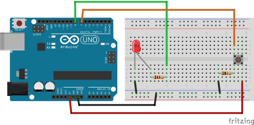
Here’s the circuit you have to make.
Step by step instructions to build the circuit (more info about Arduino pins here):
- First, make sure to power off your Arduino – remove any USB cable.
- Plug a black wire between the blue line of the breadboard and a ground (GND) pin on the Arduino board.
- Plug the LED. You can notice that the LED has a leg shorter than the other. Plug this shorter leg to the ground (blue line here) of the circuit.
- Connect the longer leg of the LED to a digital pin (here pin no 8, you can change it). Add a 220 Ohm resistor in between to limit the current going through the LED.
- Add the push button to the breadboard, like in the picture.
- Connect one leg of the button to the ground, and put a 10k Ohm resistor in between. This resistor will act as a “pull down” resistor, which means that the default button’s state will be LOW.
- Add a red wire between another leg of the button and VCC (5V).
- Finally, connect a leg of the button (same side as the pull down resistor) to a digital pin (here 7).
All right your circuit is now finished. You can start writing code.
Turn on the LED when button is pressed, turn it off otherwise
What we want to achieve is simple: when the button is not pressed, the LED is off. And when we press the button the LED should be on.
The code
Let’s break this code down line by line.
Setup
First, as a best practice, we use some defines to keep the pin number for the LED and push button. That way, if you have used different pins than I, you just need to modify those 2 lines. Also, in the future if you want to change the LED from pin 8 to pin 11 for example, you can modify this line without touching anything else in the code.
The setup function is executed once at the beginning of the program. This is the perfect time to initialize our pins with the pinMode() function:
- OUTPUT for the LED, as we’re going to write data to it.
- INPUT for the push button, as we’re going to read data from it.
Now, the digital pins are correctly set up.
Loop – Turn on the LED when button is pressed
In the loop function, we start by reading the button’s state with the digitalRead() function. As we have a pull down resistor on the button, we know that the non-pressed state will give us the value LOW.
(Note: if you were using a pull up resistor, or no resistor at all – with the INPUT_PULLUP option for pinMode – this would be the opposite. HIGH when the button is not pressed, and LOW when it’s pressed.)
So, once we get the button’s state, we check if it’s HIGH or LOW:
- HIGH (pressed): we power on the LED with digitalWrite() and the HIGH state.
- LOW (not pressed): we power off the LED with digitalWrite() and the LOW state.
OK, now let’s do something a little bit more complex.
Toggle LED’s state with the push button – first iteration
What we want to do is to toggle the LED’s state when you press + release the button. So, the first time you release the button, the LED will turn on. The second time, it will turn off. Etc.
The code
Let’s analyze the code.
Setup
Those defines are the same as before.
We need to create 2 global variables, to keep the state of the button and the LED. In the loop we’ll use those variables to compare the previous state to the new state.
The void setup stays the same. We just set the mode for both pins.
And now the serious stuff is coming. We enter the void loop function.
Monitor the button’s state
The first thing we do is to read the button’s state and to store it inside a new local variable.
Then we can compare the current state to the last one (from the previous execution of the loop function). 4 possibilities here:
- LOW -> LOW (last -> current).
- LOW -> HIGH.
- HIGH -> LOW.
- HIGH -> HIGH.
With the condition, we only enter the next block of code if the current and last state are different. If the 2 states are the same, then we don’t enter the if and the loop function is finished for this turn.
Also, now that we have the information we want, we directly store the current state into the last state variable, so that we have the correct value for the next time we enter the loop.
At this point we have only 2 possibilities left:
- Either the previous state was LOW and the current state is HIGH (not pressed to pressed).
- Or the previous state was HIGH and the current state is LOW (pressed to not pressed).
We are only interested in the second option, so here we just have to check if the current button’s state is LOW. If that’s the case, we can now turn the LED on or off.
Toggle the LED when the button has been released
Here we toggle the state of the LED. I’m not a big fan of one-liners but this one is really handful when you just need to toggle a state. This will save you 3-4 lines of code for something really trivial.
Here’s the template for this one-liner: (condition to evaluate) ? if true use this value : if false use this value.
So, if the LED is currently powered on (ledState == HIGH), we assign the value LOW. If the LED is powered off (ledState != HIGH), we assign the value HIGH.
And the last thing we need to do is of course to physically set the state for the LED, with the new computed state.
Turn LED on and off with button – using debounce
One thing you might notice with the previous experiment: sometimes when you press and release the button, the LED’s state doesn’t change, or blinks quickly multiple times.
This is because the button is physically bouncing when you press it. Thus, many false positives will be interpreted by the Arduino. What you can do to prevent that is to add a debounce delay in your code. For example, you can decide that when the program detects a change in the button’s state, it will wait 50 milliseconds before considering another change viable.
Let’s add a few lines to our previous code.
The improved code
Now, if you run this program, you won’t have any problem with the LED’s state being changed quite randomly when you press/release the button.
And here is how we achieve that.
Debounce explained
We create 2 new global variables:
- One to decide how long we want to wait before validating a second change in the button’s state. Here it means that if the state changes, any changes after that in the next 50 milliseconds will be ignored. 50 millis is a good value, you can experiment with lower and upper values to check the behavior.
- Another one to keep the last time the state was changed, so we have a starting point to compare to.
Then, in the loop, we only start the button/LED functionality if enough time has passed since the last time the button’s state was changed.
To do that it’s quite simple: we compare the duration since the last update time to the required debounce duration.
Once the debounce delay has been passed, then we can do what we did before. And don’t forget to update the starting point for the “debounce timer” just after you detect a change in the button’s state. So, the next time the program enters the loop, it will wait for 50 milliseconds (or the value you’ve chosen) to detect new changes in the button’s state.
Conclusion – Arduino turn Led ON and OFF with button
In this tutorial you have seen how to build an Arduino circuit with an LED and a push button, and also how to control this circuit to turn the LED on and off with the button.
Even if it’s a rather simple application, there are many ways to program it. You can power on the LED only when the button is pressed, or make the LED blink when you release the button, and so on.
Another way to write the code (for the exact same functionalities) is to use Arduino interrupts – available for the boards having interrupt pins.
To go further from here, check out:
Arduino – Turn LED ON and OFF With Button的更多相关文章
- 使用Arduino和LED光柱显示器件轻松制作电池电压指示器
电池有一定的电压限制,如果电压在充电或放电时超出规定的限制,电池的使用寿命就会受到影响或降低.每当我们使用电池供电的项目,有时我们需要检查电池电压电量,确定是否需要充电或更换.本电路将帮助您监测电池电 ...
- Arduino控制LED灯(开关控制)
问题:当使用"digitalRead(BUT) == 1"控制LED灯时会出现"digitalWrite(LED, ledState);"的值出现跳动. 原因: ...
- Arduino uno LED灯实验
http://jingyan.baidu.com/article/a65957f4e358d924e67f9bad.html
- Arduino关于旋转编码器程序的介绍(Reading Rotary Encoders)--by Markdown
介绍 旋转或编码器是一个角度測量装置. 他用作精确測量电机的旋转角度或者用来控制控制轮子(能够无限旋转,而电位器只能旋转到特定位置).其中有一些还安装了一个能够在轴上按的button,就像音乐播放器的 ...
- Arduino 串行外设接口——W3Cschool
来源:https://www.w3cschool.cn/arduino/arduino_serial_peripheral_interface.html Arduino 串行外设接口 由 drbear ...
- FL2440驱动添加(4)LED 驱动添加
硬件信息:FL2440板子,s3c2440CPU带四个LED,分别在链接GPB5,GPB6,GPB8,GPB10 内核版本:linux-3.8.0 led驱动代码如下: 值得注意地方地方: 1,定时器 ...
- fl2440 platform总线led字符设备驱动
首先需要知道的是,设备跟驱动是分开的.设备通过struct device来定义,也可以自己将结构体封装到自己定义的device结构体中: 例如:struct platform_device: 在inc ...
- 如何用 JavaScript 控制 Arduino?
Arduino 运行 C 语言,而主控端运行 JavaScript,一次要编写和维护两种程序.既然浏览器和服务器都用 JavaScript,若 Arduino 也能用 JavaScript 控制,那岂 ...
- Arduino系列之智能家居蓝牙语音遥控灯(四)
用到的材料 Arduino uno hc-05 蓝牙模块 安卓手机 安卓APP AMR—voice 通过安卓手机连接Arduino的蓝牙模块Hc-05,通过语音识别软件AMR-voice识别语音, ...
- 「雕爷学编程」Arduino动手做(20)—水银开关模块
37款传感器与模块的提法,在网络上广泛流传,其实Arduino能够兼容的传感器模块肯定是不止37种的.鉴于本人手头积累了一些传感器和模块,依照实践出真知(一定要动手做)的理念,以学习和交流为目的,这里 ...
随机推荐
- C++调用tensorflow模型
C++ 和python的混合编程 windows + vs 新建一个工程,在工程属性中添加如下的几个 C:\Users\[user_name]\Anaconda3\include C:\Users\[ ...
- python接口自动化封装导出excel方法和读写excel数据
一.首先需要思考,我们在页面导出excel,用python导出如何写入文件的 封装前需要确认python导出excel接口返回的是一个什么样的数据类型 如下:我们先看下不对返回结果做处理,直接接收数据 ...
- 好用的log4j.properties配置文件(按照级别打印日志,每天生成不同类型的日志,可以打印sql日志)
日志按照级别分类 log4j.rootLogger = INFO,stdout,D,E,I #ShuChuDaoDaYingTai log4j.appender.stdout = org.apache ...
- 【活动回顾】WebRTC服务端工程实践和优化探索
11月7日,即构和上海GDG技术社区联合举办了实时音视频技术云上技术分享专场,来自即构科技和Bilibili的资深技术专家进行了深度分享.大会吸引了众多开发人员交流.观看,并在活动过程中与分享嘉宾进行 ...
- Federated Learning001
联邦学习--笔记001 2022.11.16周三 今天学习了联邦学习的开山之作---Communication-Efficient Learning of Deep Networks from Dec ...
- 万字长文 | Hadoop 上云: 存算分离架构设计与迁移实践
一面数据原有的技术架构是在线下机房中使用 CDH 构建的大数据集群.自公司成立以来,每年都保持着高速增长,业务的增长带来了数据量的剧增. 在过去几年中,我们按照每 1 到 2 年的规划扩容硬件,但往往 ...
- Hexo博客Next主题相册搭建
参考文章,小红鸡 参考文章,主题美化 效果展示:相册 在blog文件夹/source下创建photos文件夹,在photos文件夹创建index.md文件,编辑index.md文件,写入以下代码: & ...
- 【Azure Event Hub】Event Hub的Process Data页面无法通过JSON格式预览数据
问题描述 在Event Hub的门户页面中,可以通过Process Data页面查看Event Hub中的数据,但是当使用JSON格式预览时(View in JSON),却出现错误. 消息一: No ...
- 图技术在 LLM 下的应用:知识图谱驱动的大语言模型 Llama Index
LLM 如火如荼地发展了大半年,各类大模型和相关框架也逐步成型,可被大家应用到业务实际中.在这个过程中,我们可能会遇到一类问题是:现有的哪些数据,如何更好地与 LLM 对接上.像是大家都在用的知识图谱 ...
- 记一次 .NET 某物流API系统 CPU爆高分析
一:背景 1. 讲故事 前段时间有位朋友找到我,说他程序CPU直接被打满了,让我帮忙看下怎么回事,截图如下: 看了下是两个相同的程序,既然被打满了那就抓一个 dump 看看到底咋回事. 二:为什么会打 ...