(6)s3c2440用I2C接口访问EEPROM
在前面阅读理解了I2C的官方协议文档后,就拿s3c2440和EEPROM来验证一下.
本来是想用s3c2440的SDA和SCL管脚复用为GPIO来模拟的,但在没有示波器的情况下搞了一周,怎么都出不来,最后还是放弃了.甚至参考了linux下i2c-algo-bit.c和i2c-gpio.c,依然没调出来.如果有示波器,可能很快就能找到原因,现在完全不知道问题出在哪里.其实想用GPIO模拟I2C的目的很简单,以一种简单而又深刻的方式来理解I2C.
既然这条路暂时没法走,退而求其次,用s3c2440的I2C接口来访问EEPROM,只要按照datasheet的来做,基本上不用考虑时序咯.
从s3c2440和AT24C02A的datasheet开始:
s3c2440的介绍其实很简单,IIC-bus接口有四种操作模式:
Master transmitter mode Master receive mode Slave transmitter mode Slave receive mode
但实际上,我们只会用到M-Tx和M-Rx,因为在s3c2440和EEPROM的连接中,没办法将s3c2440当作slave.
然后s3c2440的datasheet从I2C的协议文档上copy了一些内容:开始终止条件\数据传输格式\ACK\读写操作\总线仲裁\终止条件等.这些还是看I2C的协议文档比较好.
I2C-BUS的配置:
为了控制SCL的频率,IICCON中可以控制一个4bit的分频器.IICADD寄存器用来保存IIC-Bus的接口地址,这个实际也无需用,只有访问从设备时才需要地址.而这里s3c2440是主设备.
在每次IIC Tx/Rx操作前,都要做下面的操作:
如果需要的话,写从地址到IICADD
设置IICCON寄存器(使能中断,定义SCL的周期)
设置IICSTAT来使能串行输出
然后就是M-Tx和M-Rx操作模式的流程图,后面的代码就是严格按照这个图来的.这里就不截图了.
寄存器的说明大概如下:
#define rIICCON (*(volatile unsigned *)0x54000000) /********************** [7]:ack enable bit [6]:Tx clock source selection 0:IICCLK = PCLK/16 1:IICCLK = PCLK/512 [5]:Tx/Rx interrupt [4]:interrupt pending flag !!!! [3:0]:Tx clock = IICCLK/(IICCON[3:0]+1) **********************/ #define rIICSTAT (*(volatile unsigned *)0x54000004) /********** [7:6]:10:M-Rx 11:M-Tx [5]:busy signal status/start stop conditon !!! [4]:serial output enable/disable bit 1:enable [3]:iic arbitration procedure status flag bit || which didn't used [2]:address-as-slave status flag !!! [1]:address zero status flag [0]:last-received bit status flag 0:ack 1:nack **********/ #define rIICADD (*(volatile unsigned *)0x54000008) /********* * [7:1]:slave address 只有在IICSTAT的output disable时,IICADD才可以写.随时可以读. * ************/ #define rIICDS (*(volatile unsigned *)0x5400000c) /************** * [7:0]:8bit data shift reg for IIC-Bus Tx/Rx operation.只有IICSTAT的output enable时,IICDS才可以写.随时可以读. * *************/ #define rIICLC (*(volatile unsigned *)0x54000010) /************** * 该寄存器用于多主机的情况,暂时用不到 * ************/
下面看下AT24C02A的datasheet:
AT24C02A:2K的容量,32pages,每个page8个字节,总共256字节.读写需要8bit的word address.
AT24C02A的地址是从下图来的:

所以地址就是我们看到的0xa0,A2 A1 A0因为在原理图上这三个管脚都接的低电平.
写操作:
以字节写的图为例:
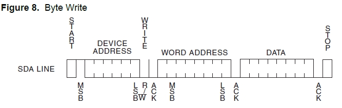
结合s3c2440的M-Tx模式,代码操作如下:
- void I_Write(unsigned int slvaddr, unsigned char addr, unsigned char data)
- {
- unsigned int ack;
- init(slvaddr);
- //rIICSTAT |= 0x3<<6; //configure M Tx mode
- rIICDS = slvaddr;//0xa0; //write slave address to IICDS
- rIICCON&=~0x10; //clear pending bit
- rIICSTAT = 0xf0; //(M/T start)
- //the data of the IICDS is transmitted
- uart_SendByte('a');
- while((rIICCON & 1<<4) == 0);//udelay(10);//ack period and then interrupt is pending
- if((rIICSTAT & 0x01)==0)
- uart_SendByte('y');//ack = 0; //收到应答
- else
- uart_SendByte('n');//ack = 1; //没有应答
- rIICDS = addr;
- rIICCON&=~0x10; //clear pending bit
- //the data of the IICDS is shifted to sda
- uart_SendByte('b');
- while((rIICCON & 1<<4) == 0);//udelay(10);//ack period and then interrupt is pending
- if((rIICSTAT & 0x01)==0)
- uart_SendByte('y');//ack = 0; //收到应答
- else
- uart_SendByte('n');//ack = 1; //没有应答
- rIICDS = data;
- rIICCON&=~0x10; //clear pending bit
- //the data of the IICDS is shifted to sda
- uart_SendByte('c');
- while((rIICCON & 1<<4) == 0);//udelay(10);//ack period and then interrupt is pending
- if((rIICSTAT & 0x01)==0)
- uart_SendByte('y');//ack = 0; //收到应答
- else
- uart_SendByte('n');//ack = 1; //没有应答
- rIICSTAT = 0xD0; //write (M/T stop to IICSTAT)
- //rIICCON = 0xe0;
- rIICCON&=~0x10; //clear pending bit
- uart_SendByte('d');
- while((rIICSTAT & 1<<5) == 1);
- }
void I_Write(unsigned int slvaddr, unsigned char addr, unsigned char data)

{

	unsigned int ack;

	init(slvaddr);

	//rIICSTAT |= 0x3<<6;  //configure M Tx mode

	rIICDS = slvaddr;//0xa0;  //write slave address to IICDS

	rIICCON&=~0x10; //clear pending bit

	rIICSTAT = 0xf0;  //(M/T start)

	//the data of the IICDS is transmitted

	uart_SendByte('a');

	while((rIICCON & 1<<4) == 0);//udelay(10);//ack period and then interrupt is pending

	if((rIICSTAT & 0x01)==0)

		uart_SendByte('y');//ack = 0;    //收到应答

	else

		uart_SendByte('n');//ack = 1;    //没有应答

	rIICDS = addr;

	rIICCON&=~0x10; //clear pending bit

	//the data of the IICDS is shifted to sda

	uart_SendByte('b');

	while((rIICCON & 1<<4) == 0);//udelay(10);//ack period and then interrupt is pending

	if((rIICSTAT & 0x01)==0)

		uart_SendByte('y');//ack = 0;    //收到应答

	else

		uart_SendByte('n');//ack = 1;    //没有应答

	rIICDS = data;

	rIICCON&=~0x10; //clear pending bit

	//the data of the IICDS is shifted to sda

	uart_SendByte('c');

	while((rIICCON & 1<<4) == 0);//udelay(10);//ack period and then interrupt is pending

	if((rIICSTAT & 0x01)==0)

		uart_SendByte('y');//ack = 0;    //收到应答

	else

		uart_SendByte('n');//ack = 1;    //没有应答

	rIICSTAT = 0xD0; //write (M/T stop to IICSTAT)

	//rIICCON = 0xe0;

	rIICCON&=~0x10; //clear pending bit

	uart_SendByte('d');

	while((rIICSTAT & 1<<5) == 1);

}
读操作:
以随机读的图为例:
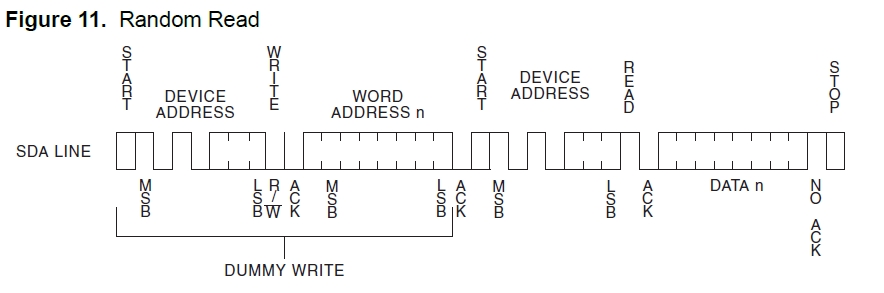
随机读要复杂点,因为前面的DUMMY WRITE要用M-Tx模式,而后面真正的读操作要用M-Rx模式.结合s3c2440的模式操作的流程图,代码如下:
- unsigned char I_Read(unsigned int slvaddr, unsigned char addr)
- {
- unsigned char data;
- int ack;
- init(slvaddr);
- //rIICSTAT |= 0x3<<6; //configure M Tx mode
- rIICDS = slvaddr;//0xa0; //write slave address to IICDS
- rIICCON&=~0x10; //clear pending bit
- rIICSTAT = 0xf0; //(M/T start)
- //the data of the IICDS is transmitted
- while((rIICCON & 1<<4) == 0);//udelay(10);//ack period and then interrupt is pending
- if((rIICSTAT & 0x01)==0)
- uart_SendByte('y');//ack = 0; //收到应答
- else
- uart_SendByte('n');//ack = 1; //没有应答
- rIICDS = addr;
- rIICCON&=~0x10; //clear pending bit
- //the data of the IICDS is shifted to sda
- while((rIICCON & 1<<4) == 0);//udelay(10);//ack period and then interrupt is pending
- if((rIICSTAT & 0x01)==0)
- uart_SendByte('y');//ack = 0; //收到应答
- else
- uart_SendByte('n');//ack = 1; //没有应答
- init(slvaddr);
- rIICSTAT &= ~(0x1<<6);//configure M Rx mode
- rIICSTAT |= 0x1<<7;
- //rIICSTAT |= 0x2<<6; //configure M Rx mode
- rIICDS = slvaddr;
- rIICCON&=~0x10; //clear pending bit
- rIICSTAT = 0xb0; //(M/R Start)
- //the data of IICDS(slave address) is transmitted
- while((rIICCON & 1<<4) == 0);//udelay(10);//uart_SendByte('o');//ack period and then interrupt is pending::
- if((rIICSTAT & 0x01)==0)
- uart_SendByte('y');//ack = 0; //收到应答
- else
- uart_SendByte('n');//ack = 1; //没有应答
- data = rIICDS;
- if(data==160)
- uart_SendByte('o');
- rIICCON&=~0x10; //clear pending bit
- //sda is shifted to IICDS
- while((rIICCON & 1<<4) == 0);//udelay(10);//ack period and then interrupt is pending
- if((rIICSTAT & 0x01)==0)
- uart_SendByte('y');//ack = 0; //收到应答
- else
- uart_SendByte('n');//ack = 1; //没有应答
- uart_SendByte('a');
- rIICSTAT = 0x90;
- uart_SendByte('b');
- rIICCON&=~0x10; //clear pending bit
- uart_SendByte('c');
- while((rIICSTAT & 1<<5) == 1)uart_SendByte('o');
- uart_SendByte('d');
- return data;
- }
unsigned char I_Read(unsigned int slvaddr, unsigned char addr)

{

	unsigned char data;

	int ack;

	init(slvaddr);

	//rIICSTAT |= 0x3<<6;  //configure M Tx mode

	rIICDS = slvaddr;//0xa0;  //write slave address to IICDS

	rIICCON&=~0x10; //clear pending bit

	rIICSTAT = 0xf0;  //(M/T start)

	//the data of the IICDS is transmitted

	while((rIICCON & 1<<4) == 0);//udelay(10);//ack period and then interrupt is pending

	if((rIICSTAT & 0x01)==0)

		uart_SendByte('y');//ack = 0;    //收到应答

	else

		uart_SendByte('n');//ack = 1;    //没有应答

	rIICDS = addr;

	rIICCON&=~0x10; //clear pending bit

	//the data of the IICDS is shifted to sda

	while((rIICCON & 1<<4) == 0);//udelay(10);//ack period and then interrupt is pending

	if((rIICSTAT & 0x01)==0)

		uart_SendByte('y');//ack = 0;    //收到应答

	else

		uart_SendByte('n');//ack = 1;    //没有应答

	init(slvaddr);

	rIICSTAT &= ~(0x1<<6);//configure M Rx mode

	rIICSTAT |= 0x1<<7;

	//rIICSTAT |= 0x2<<6;  //configure M Rx mode

	rIICDS = slvaddr;

	rIICCON&=~0x10; //clear pending bit

	rIICSTAT = 0xb0;  //(M/R Start)

	//the data of IICDS(slave address) is transmitted

	while((rIICCON & 1<<4) == 0);//udelay(10);//uart_SendByte('o');//ack period and then interrupt is pending::

	if((rIICSTAT & 0x01)==0)

		uart_SendByte('y');//ack = 0;    //收到应答

	else

		uart_SendByte('n');//ack = 1;    //没有应答

	data = rIICDS;

	if(data==160)

		uart_SendByte('o');

	rIICCON&=~0x10; //clear pending bit

	//sda is shifted to IICDS

	while((rIICCON & 1<<4) == 0);//udelay(10);//ack period and then interrupt is pending

	if((rIICSTAT & 0x01)==0)

		uart_SendByte('y');//ack = 0;    //收到应答

	else

		uart_SendByte('n');//ack = 1;    //没有应答

	uart_SendByte('a');

	rIICSTAT = 0x90;

	uart_SendByte('b');

	rIICCON&=~0x10; //clear pending bit

	uart_SendByte('c');

	while((rIICSTAT & 1<<5) == 1)uart_SendByte('o');

	uart_SendByte('d');

	return data;

}
这个EEPROM的其他读写操作依此类推.
最后,做一下总结:
1.单次的写字节和随机读之间应该加延时,验证过程中发现,在两次写字节之间延时100us的话,在第二次写字节的时候就收不到ACK.将延时改为1000us就正常了.
2.IICDS的读写操作一定要在清楚IIC interrupt pending bit之前做,也就是代码中出现的:
- rIICDS = slvaddr;
- rIICCON&=~0x10; //clear pending bit
	rIICDS = slvaddr;

	rIICCON&=~0x10; //clear pending bit
while((rIICCON & 1<<4) == 0);//udelay(10);//ack period and then interrupt is pending if((rIICSTAT & 0x01)==0) uart_SendByte('y');//ack = 0; //收到应答 else uart_SendByte('n');//ack = 1; //没有应答
只需要上面的代码就可以了,通过轮询IICCON的第4bit来查看ack period and then interrupt is pending.
当然如果用中断系统中IIC中断也是可以的,一个是中断方式,一个是轮询方式,在这里感觉差别不大.
关于I2C裸机到此为止,但是gpio模拟I2c一直耿耿于怀啊~~
在工作中,linux下做过用I2C子系统用GPIO模拟I2C.那个只要配置好GPIO的input和output,构造数据结构,驱动就能工作了,不得不佩服这个子系统的强大.因为前面的blog对文件系统和设备模型都做过分析,但并没有针对特定的子系统做过分析,过段时间就来分析linux的I2C,学习C语言也是如何实现OOP的某些特性的,体会好代码的设计思路.
(6)s3c2440用I2C接口访问EEPROM的更多相关文章
- JZ2440 裸机驱动 第12章 I2C接口
本章目标: 了解I2C总线协议: 掌握S3C2410/S3C2440中I2C接口的使用方法: 12.1 I2C总线协议及硬件介绍 12.1.1 I2C总线协议 1 I2C总线的概念 2 I2C总线的信 ...
- EEPROM的操作---SPI接口和I2C接口
参考:http://blog.csdn.net/yuanlulu/article/details/6163106 ROM最初不能编程,出厂什么内容就永远什么内容,不灵活.后来出现了PROM,可以自己写 ...
- S3C2440—7.存储控制器访问外设
文章目录 一.内存接口的概念 二.存储控制器(内存控制器) 2.1 什么是存储控制器? 2.2 S3C2440存储控制器介绍 2.3 存储控制器如何处理不同位宽的外设 2.4 怎么确定芯片的访问地址? ...
- 通过I2C总线向EEPROM中写入数据,记录开机次数
没买板子之前,用protues画过电路图,实现了通过i2c总线向EEPROM中写入和读出数据. 今天,在自己买的板子上面写关于i2c总线的程序,有个地方忘了延时,调程序的时候很蛋疼.下面说说我对I2c ...
- 解决STM32 I2C接口死锁在BUSY状态的方法讨论
关于STM32的I2C接口死锁在BUSY状态无法恢复的现象,网上已有很多讨论,看早几年比较老的贴子,有人提到复位MCU也无法恢复.只有断电才行的状况,那可是相当严重的问题.类似复位也无法恢复的情况是存 ...
- seller【2】Mock数据(接口访问配置)
Mock数据 在文件[vue.config.js] - devServer 字段 - before(app)函数配置数据接口访问 const appData = require('./data.jso ...
- 树莓派配置RTC时钟(DS3231,I2C接口)
1.购买基于DS3231的RTC时钟模块,并且支持3.3V的那种 2.配置树莓派 a.打开树莓派的i2c接口 sudo raspi-config -->Interfacing Options - ...
- redis 限制接口访问频率
代码: <?php /** * */ class myRedis { private static $redis = null; /** * @return null|Redis */ publ ...
- Vue解决接口访问跨域问题
随手摘录 Vue解决接口访问跨域问题 1.打开 config -> index.js 2. 找到proxyTable 3.粘贴 如下代码,'https://www.baidu.com'换成要访问 ...
随机推荐
- compass(sass)+seajs+frozenui+frozenjs+svn主干分支
1.compass框架 sass编译 1.compass create 项目名 2.cd目录,执行compass watch 2.frozen框架 js(frozen.js),css(global.c ...
- gentoo下grub文件编辑
在编译完内核,配置好网络,配置好fstab文件等等,最后一个至关重要的文件要属grub文件了,该文件的配置成功才最终决定gentoo 是否成功装上,首先当然是 emerge grub 了,现在就可以配 ...
- php中一些安全性防止问题建议
只要我们作好了各类操作就可在基本防止一些朋友利用网站本身的漏洞进行网站操作了,很多在php中都有的如XSS用 htmlentities()预防XSS攻击还有sql注入可以用mysql_real_esc ...
- ubuntu 12.04 安装 nginx+php+mysql web服务器
Nginx 是一个轻量级,以占用系统资源少,运行效率而成为web服务器的后起之秀,国内现在很多大型网站都以使用nginx,包括腾讯.新浪等大型信息网站,还有淘宝网站使用的是nginx二次开发的web服 ...
- MFC应用程序的开发流程
(1)根据应用程序特性在"MFC AppWizard[exe]"应用程序向导各步骤对话框进行选择,创建一个应用程序的框架. (2)利用资源编辑器为程序编辑或添加资源,如编辑菜单.添 ...
- MVC-列表页操作按钮调用脚本
如上图所示功能:点击右边的“编辑”和“重置按钮”,调用js实现弹出框功能. 1.写脚本: <script type="text/javascript"> functio ...
- MVC-登录并设置角色
1.新建一个类,设置角色: using System; using System.Collections.Generic; using System.Linq; using System.Text; ...
- Xcode 7.3.1的模拟器路径
/Applications/Xcode.app/Contents/Developer/Platforms/iPhoneSimulator.platform/Developer/Library/Core ...
- SWFUpload 按钮显示问题
问题: 今天遇到一个这样的问题,我用Vs2010打开用SWFUpload上传文件的网页时,按钮显示不出来,试了好多方法,终于被我找到了! 解决方法: 原来是vs2010自带的Asp.net Devel ...
- [XJOI NOI2015模拟题13] B 最小公倍数 【找规律】
题目链接:XJOI - NOI2015-13 - B 题目分析 通过神奇的观察+打表+猜测,有以下规律和性质: 1) 删除的 n 个数就是 1~n. 2) 当 c = 2 时,如果 n + 1 是偶数 ...