
Simple Addition Permits Voltage Control Of DC-DC Converter's Output
http://electronicdesign.com/power/simple-addition-permits-voltage-control-dc-dc-converters-output
In a standard dc-dc converter, a resistor divider typically defines a fixed output voltage. However, applications like programmable output voltage power supplies and motor control circuits require dynamic control of the dc-dc converter’s output voltage. The circuit described here allows control of the converter’s output voltage, VOut, with a control voltage, VC.
In a conventional dc-dc buck converter, VOut is:

so VOut is fixed by the values of R1 and R2 (Fig. 1).
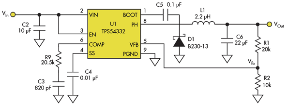
1. The output voltage in a conventional dc-dc buck converter is fixed and depends on the resistor divider, R1/R2.
The added circuitry in Figure 2 enables users to control the same dc-dc converter’s output voltage using VC.
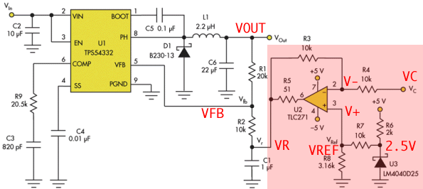
In this case, R2 is not connected to the ground but, rather, to Vr. Equation 1 then becomes:
VOUT = VFB + ( ( VFB - VR ) / R2 ) * R1
VOUT - VR = VFB - VR + ( ( VFB - VR ) / R2 ) * R1
VOUT - VR = ( VFB - VR ) * R2 / R2 + ( VFB - VR ) * R1 / R2
VOUT - VR = ( VFB - VR ) * ( R2 + R1 ) / R2

Since R1 = 20 kΩ and R2 = 10 kΩ, Equation 2 can be simplified to:
VOut – Vr = 3(Vfb – Vr)(3)
or:
VOut = 3 Vfb – 2 Vr(4)
( VC - V- ) / R4 = ( V- - VR ) / R3 ( I4 = I3 )
VC / R4 - V- / R4 = V- / R3 - VR / R3
V- / R4 + V- / R3 = VC / R4 + VR / R3
V- * ( R3 + R4 ) / ( R3 * R4 ) = ( VC * R3 + VR * R4 )/ ( R3 * R4 )
V- * ( R3 + R4 ) = ( VC * R3 + VR * R4 )
VR * R4 = V- * ( R3 + R4 ) - VC * R3
V- = V+ = VREF : VR * R4 = VREF * ( R3 + R4 ) - VC * R3
R3 = R4 : VR * R3 = VREF * ( R3 + R3 ) - VC * R3
VR = VREF * 2 - VC
R3 and R4 have the same value, 10 kΩ, so amplifier U2’s output voltage is:
Vr = 2 VRef – VC(5)
where VRef is the reference voltage generated by U3 after resistor divider R7/R8.
VOut = 3 Vfb – 2 Vr(4)
Combining Equation 4 and Equation 5:
VOut = 3 Vfb – 4 VRef + 2 VC (6)
To simplify Equation 6, choose components that make:
3 Vfb = 4 VRef(7)
Then Equation 6 becomes:
VOut = 2 VC (8)
The internal voltage reference of U1 is 0.8 V. ( TPS54332 )
VREF = 3VFB / 4 = 3 *0.8 / 4 = 0.6V
LM4040D25 : 2.5V : By choosing R7 = 10 kΩ and R8 = 3.16 kΩ, VRef = 0.6 V, satisfying Equation 7.
Finally, C1 lowers U2’s output impedance at high frequencies,
maintaining the stability of U1’s feedback loop.
The added circuitry allows users to control the buck converter’s output voltage,
VOut, in the range of 0 to 5 V with a control voltage, VC, in the range of 0 to 2.5 V.
Similar circuitry can be designed for use with a boost converter,
or any other dc-dc converter, as long as its feedback voltage pin is accessible.
Using an operational amplifier in the feedback path
A very flexible way of influencing the feedback pin while not being so restricted
in terms of the control signal is to use an operational amplifier.
It can be used to inject some current into the feedback divider which then
forces the control loop of the power supply to change the output voltage.
This way the output voltage can be varied continuously as a function
of the current injected into the feedback node.
Often, the information controlling the output voltage change on a power supply in sensor applications
as well as motor drive applications is an analog signal.
Depending on the nature of this control signal, the circuit around the operational amplifier
can be defined to set the lowest voltage output independent of what the control signal range is.
Also there is great flexibility in the ratio of control signal change to change in the output voltage.
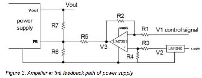
Figure 3 shows an amplifier circuit in the feedback path of a switching power supply.
The difference amplifier uses an operational amplifier and four additional resistors R1 through R4.
The output of the operational amplifier acts like a voltage source.
In order to inject a current into the feedback node this voltage is converted into a current by resistor R5.
It equals the internal impedance of the current source which the operational amplifier and R5 constitute.
Together with the feedback resistors R6 and R7 any output voltage changes
can be set based on almost any given control signal.
The signal voltage V1 is the control signal.
The voltage V2 is a reference voltage for the operational amplifier.
It should be a fairly constant voltage since variations on it will
change the output voltage of the power supply as well.
If a fairly precise rail in the system is available it can generally be used.
A good solution is a low voltage reference IC such as National Semiconductors LM4040.
Simple Addition Permits Voltage Control Of DC-DC Converter's Output的更多相关文章
- Simple dc/dc converter increases available power in dual-voltage system
The schematic in Figure 1 shows a way to increase the power available from a current-limited 5V supp ...
- PID DC/DC Converter Controller Using a PICmicro Microcontroller
http://www.microchip.com/stellent/idcplg?IdcService=SS_GET_PAGE&nodeId=1824&appnote=en011794 ...
- LT1946A-- Transformerless dc/dc converter produces bipolar outputs
Dual-polarity supply provides ±12V from one IC VC (Pin 1): Error Amplifier Output Pin. Tie external ...
- Practice safe dc/dc converter
Short-circuit protection is an obvious requirement for a power supply, especially when its load conn ...
- [专业名词·硬件] 2、DC\DC、LDO电源稳压基本常识(包含基本原理、高效率模块设计、常见问题、基于nRF51822电源管理模块分析等)·长文
综述先看这里 第一节的1.1简单介绍了DC/DC是什么: 第二节是关于DC/DC的常见的疑问答疑,非常实用: 第三节是针对nRF51822这款芯片电源管理部分的DC/DC.LDO.1.8的详细分析,对 ...
- DC/DC与LDO的差别
转自:http://bbs.eetop.cn/thread-459121-1-1.html 在平时的学习中,我们都有接触LDO和DC/DC这一类的电源产品,但作为学生的我们队这些东西可能了解不够深刻, ...
- Add margining capability to a dc/dc converter
You can easily add margining capability—that is, the ability to digitally adjust the output voltage— ...
- DC DC降壓變換器ic 工作原理
目前DC/DC轉化器大致可分為:升壓型dc dc變化器.降壓型dc dc變化器及可升壓又可降壓dc dc變換器.我們今天主要提一下降壓型dc dc變換器的原理: 見下圖降壓變換器原理圖如圖1所示, 當 ...
- DC DC電路電感的選擇
注:只有充分理解電感在DC/DC電路中發揮的作用,才能更優的設計DC/DC電路.本文還包括對同步DC/DC及異步DC/DC概念的解釋. DCDC電路電感的選擇 簡介 在開關電源的設計中電感的設計為 ...
随机推荐
- Ubuntu连接多台Ubuntu server的问题
如果您用的是虚拟机上安装的几个Ubuntu server进行IP配置 要注意以下几点: <1>虚拟机上安装完成Ubuntu server 默认的网络连接方式是NAT ,应该改成桥接网卡 ( ...
- Mac——mac安装软件
命令行: perl: curl -L http://xrl.us/installperlosx | bash 参考资料: https://blog.csdn.net/yuxin6866/article ...
- 第 18 章 Django 入门
当今的网站实际上都是富应用程序(rich application),就像成熟的桌面应用程序一样.Python提供了一组开发Web应用程序的卓越工具.在本章中,我们将学习如何使用Django(http: ...
- Java反序列化漏洞之殇
ref:https://xz.aliyun.com/t/2043 小结: 3.2.2版本之前的Apache-CommonsCollections存在该漏洞(不只该包)1.漏洞触发场景 在java编写的 ...
- Wannafly挑战赛7 D - codeJan与青蛙
codeJan喜欢观察世界.有一天,codeJan发现一个非常奇怪的现象.有一些年轻的青蛙聚集在一条直线上的某些位置上,同一个位置可能有多个青蛙.这些青蛙每次只会向前跳一米,并且每只青蛙每跳一次都会发 ...
- 消息中间件ActiveMQ使用详解
消息中间件ActiveMQ使用详解 一.消息中间件的介绍 介绍 消息队列 是指利用 高效可靠 的 消息传递机制 进行与平台无关的 数据交流,并基于 数据通信 来进行分布式系统的集成. 特点(作用) ...
- 什么情况下调用doGet()和doPost()?
Jsp页面中的FORM标签里的method属性为get时调用doGet(),为post时调用doPost().
- 缩略图信息提取工具vinetto
缩略图信息提取工具vinetto 在Windows操作系统中,为了方便用户快速浏览图片,系统会自动为每个图片生成预览图.预览图默认保存在同目录的Thumbs.db文件中.当图片文件删除后,Thum ...
- 创建模态提醒窗口(UIAlertView)
UIAlertView类创建一个简单的模态提醒窗口,可能包含消息.按钮以及文本框.模态UI元素要求用户必须与之交互(通常是按下按钮)后才能做其它事情.它们通常位于其他窗口前面,在可见时禁止用户与其他任 ...
- FastReport.Net使用:[34]小册子报表(奇偶页)
打印一份小册子类型的报表,能实现如下要求: ●单独的封面,目录,报表内容,背面 ●奇偶页不同的页边距 ●奇偶页不同的页面/页脚 下面的例子将用到以上3点. 1.奇偶页的实现主要通过报表控件对象的Pri ...