反接保护电路 Reverse Voltage Protection
I've long wanted to pull together some reverse polarity protection ideas in one place.
Many are found individually on the web, but seldom several in one place.
A recent QRP-L thread prompted me to put together this page.
I haven't tried all of them, and none are original with me.
I'm just pulling together ideas from others. You're on your own for circuit and part selection.
Click on the pictures for a larger image if needed. Please email if you wish me to add a circuit,
have a comment about the page, or if you spot any errors. Thank you es 72 ... WAØITP
Blocking Diode
 |
|
Full Wave Rectifier
 |
|
P Channel MOSFET - PMOS
 |
|
Regulator - PNP or LDO
 |
|
Fuse and Diode
 |
|
Resettable Fuse
 |
|
Relay with NC Contacts
 |
|
Relay with NO Contacts
 |
|
NMOS with Specialized IC
 |
|
Anderson Power Poles
 |
|
Anderson Power Pole Checker
 |
|
Using MOSFETs as blocking diodes
Connecting a battery backwards to an electronic circuit can rapidly do a lot of damage — current will flood through (and destroy) many integrated circuits when powered up the wrong way, and electrolytic capacitors have a famous tendency to explode. For this reason, it’s common to use a blocking diode in a circuit to provide reverse polarity protection:
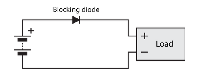
If the battery is connected correctly, as shown, current flows through the diode to the circuit, and the circuit operates normally. If the battery is reversed, the battery tries to pull current through the diode the wrong way, and the diode refuses to conduct — protecting the load from damage.
The diode can also be placed on the low rail, as shown below. This is completely equivalent to the circuit shown above for battery-powered applications. However, it may make less sense in circuit provided positive DC power by an external supply, where having a consistent ground can be important. On the flip side, a circuit that operates using negative DC power (which is much rarer) would be much better off with the circuit below for the same reason.

This blocking diode approach works great for many applications. However, when the diode is conducting, there is a voltage drop across it (typically around 0.7V for silicon diodes, 0.2V for Schottky diodes) which means that the load sees a bit less voltage across it. This is a particularly major problem for low voltage applications, where a 0.3V drop can represent almost 10% of a 3.3V system’s power, wasted at the very first component. For higher power applications, a fair bit of power can be wasted as heat in the diode as well.
An alternative solution: MOSFETs
The wonderful thing about MOSFETs is that they can be designed to have incredibly low voltage drops, which translates into less waste heat and more voltage for the load to operate. You can routinely get MOSFETs with resistances of 20 milliohms and below, which translates to allowing 5 amps to pass with a drop of only 0.1V, less than any diode.
You can’t just use them as a direct drop-in replacement, though, because you have to drive the gate of the MOSFET somehow. Here’s the trick: you can just use the other terminal of the battery for this:

So, how does this work? I’m going to define the voltage of the bottom net, 


At the instant that the battery is connected, 
It turns out that this design actually relies on the body diode to work, at least briefly. Current will flow through the body diode to the load, raising
When reverse biased, the body diode will be reverse biased, and will therefore not conduct.
An N-channel FET can be used on the bottom rail instead, like so:
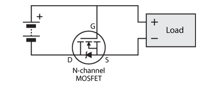
The same comments apply as for the aforementioned blocking diode on the bottom rail. There’s one additional advantage here, though: N-channel FETs tend to have better performance characteristics than P-channel FETs (although these days, both are remarkably excellent).
What’s the catch?
There are a number of reasons why this MOSFET circuit is not always a suitable replacement for a normal blocking diode:
- Some blocking diodes are used in applications where current from a generator is used to charge two separate batteries. If one battery ends up with a higher voltage than another, the blocking diodes prevent electricity from flowing out of the higher voltage battery, back onto the generator leads, and into the other battery. The circuit above will completely fail at this job, because
- It might not always be easy to physically connect the gate of the MOSFET to the opposite rail, especially with a circuit laid out with a normal diode in mind.
- MOSFETs have a few more maximum limits to check and look after than diode, owing mostly to the fact the a MOSFET has an extra leg. This isn’t a practical disadvantage, just something to be careful about.
Is it safe to pass current through the MOSFET in the non-conventional direction?
It might seem unusual to pass current up through the MOSFET, especially since the curves in datasheets don’t seem to cover this region. However, operation in this so-called third quadrant is routinely used in buck converters, where a MOSFET is used to replace the reverse recovery diode (source). The reasons for replacing the reverse recovery diode with a MOSFET are exactly the same as for replacing blocking diodes — it’s to avoid energy wasted due to diode voltage drop.
MOSFET selection
The figures below are for the P-FET design, N-FET design will be similar except with a few minus signs thrown around the place. This is just a rough guide, etc.
- The absolute maximum
should be at least
, where
is the voltage of the power supply/battery. This is because in a situation when correct polarity rapidly switches to reverse polarity, you get
,
.
- The absolute maximum
.
- Check the output characteristics to ensure that the FET is thoroughly on when
. Roughly speaking, this corresponds to
being greater than than
(remembering, e.g., –2 is greater than –9).
- And of course, check that the FET can handle the current, the power dissipated, and the heat generated. And yes, these are three related but very different things that need to be checked independently (the last is calculated using thermal resistance, given in the datasheet).
Fin.
So there you have it. If anyone out there uses this circuit because of this page, I’d love to hear about it! And as always, I will attend to any questions left below.
反接保护电路 Reverse Voltage Protection的更多相关文章
- 【charger battery 充電 充電器 電池】過充保護警告訊息 over charging protection,Battery over voltage protection, warning message
Definition: over charging protection.battery over voltage protection, 是一種 battery 保護機制, 避免 battery 充 ...
- 過充保護警告訊息 over charging protection,Battery over voltage protection, warning message
Definition: over charging protection.battery over voltage protection, 是一種 battery 保護機制, 避免 battery 充 ...
- [转] 图解单片机下载程序电路原理之USB转串口线、CH340、PL2303、MAX232芯片的使用
点击阅读原文 目前为止,我接触单片机已有不少时日,从选择元器件.原理图.PCB.电路硬件调试.软件开发也算小有心得 .单片机软件开发里面第一步当属下载程序了,如果这一步都有问题,那么后面的一切便无从谈 ...
- MOS管防反接电路设计
转自嵌入式单片机之家公众号 问题的提出 电源反接,会给电路造成损坏,不过,电源反接是不可避免的.所以,我们就需要给电路中加入保护电路,达到即使接反电源,也不会损坏的目的 01二极管防反接 通常情况下直 ...
- 自制单片机之七……扩展:DS18B20温度测量
DS18B20数字温度测量传感器,网上介绍很多,我就不罗嗦了.见图 DS18B20与前产品DS1820的不同: DS18B20继承了DS1820的全部优点,并做了如下改进 1.供电范围扩大为3.0-- ...
- 【开源GPS追踪】 之 硬件开源
根据设定目标: 使用GPS 采集经纬度,然后通过GPRS模块/wifi 发送到服务器显示,WIFI不常有,所有就使用GPRS模块! 对于GPS模块,没有特殊要求,只要输出格式符合NMEA协议即可,为了 ...
- 防止DC电源反接的方法——SS14的用法
出处:http://blog.ednchina.com/tengjingshu 电源是PCB板的重要部分,每个芯片都需要电源供给.芯片其实是挺脆弱的,只要正负接反得话,大多数就会挂掉,相信很多人都有惨 ...
- 初级模拟电路:1-2 PN结与二极管
回到目录 1. 掺杂半导体 上面我们分析了本征半导体的导电情况,但由于本征半导体的导电能力很低,没什么太大用处.所以,一般我们会对本征半导体材料进行掺杂,即使只添加了千分之一的杂质,也足以改变半导 ...
- 兼容可控硅调光的一款LED驱动电路记录
1.该款电路为兼容可控硅调光的LED驱动电路,采用OB3332为开关控制IC,拓扑方案为Buck: 2.FB1:磁珠的单位是欧姆,而不是亨利,这一点要特别注意.因为磁珠的单位是按照它在某一频率 产生的 ...
随机推荐
- 20155315 2016-2017-2 《Java程序设计》第七周学习总结
教材学习内容总结 第12章 Lambda语法 Lambda定义 一个不用被绑定到一个标识符上,并且可能被调用的函数. 在只有Lambda表达式的情况下,参数的类型必须写出来,如果有目标类型的话,在编译 ...
- python导出数据到excel
1,SMTP发送带excel附件的邮件: def sendMail(filename, addressee): """ :param content: 发送内容 :par ...
- HDU 6395 Sequence 杜教板子题
题目意思非常明确,就是叫你求第n项,据我们学校一个大佬说他推出了矩阵,但是我是菜鸡,那么肯定是用简单的方法水过啦!我们先p^(1/2)的复杂度处理出i=[i,p]范围内的所有种类的(int)(p/i) ...
- springboot整合rabbitmq客户端连接报超时异常问题解决:An unexpected connection driver error occured java.net.SocketException: Socket Closed,java.util.concurrent.TimeoutException
我用的是springboot2.0.6版本,对应的ampq也是2.0.6版本,然后启动一直报: 还有java.util.concurrent.TimeoutException, 用户授权什么的都对,很 ...
- [HNOI2007]梦幻岛宝珠 「套路:分层 $DP$」
显然直接 \(01\) 背包会超时并且超空间 套路:分层 \(DP\) 「考虑将每个子结构看作一层(也就是包含了不止 \(1\) 个物品的信息),并且大层不会对小层造成影响,可以考虑先进行每一层的自我 ...
- 巧用PHP双$功能兼容线上线下配置文件
2014年2月8日 19:27:05 情景: 开发过程中线上和线下的配置文件中的值是不一样的 例如:线上生产环境的样式域名为ie.style.abc.com,而开发环境为ie.style.abc.ne ...
- springboot中url地址重写(urlwrite)
在日常网站访问中,会把动态地址改造成伪静态地址. 例如: 访问新闻栏目 /col/1/,这是原有地址,如果这样访问,不利于搜索引擎检索收录,同时安全性也不是很好. 改造之后: /col/1.html. ...
- PHP跨域访问
1.允许所有域名访问 header('Access-Control-Allow-Origin: *'); 2.允许单个域名访问 header('Access-Control-Allow-Origin: ...
- Zookeeper命令行zkCli.sh&zkServer.sh的使用(四)
上篇博文,我们成功的安装和启动了zookeeper服务器,zookeeper还提供了很多方便的功能,方便我们查看服务器的状态,增加,修改,删除数据(入口是zkServer.sh和zkCli.sh).还 ...
- php生成随机数
生成1-10之间的随机数,不重复. 方法一:用shuffle函数. <?php $arr=range(1,10); shuffle($arr); foreach($arr as $values) ...