设备树..ing
.dts==>.dtb ==>device_node ==> platform_device ==> led_dev.c ==>匹配 led_drv.c (设备树是对平台设备总线的一种改进)
1.使用设备树时平台设备总线源码分析
平台设备总线分析:https://www.cnblogs.com/zsy12138/p/10391933.html
struct bus_type platform_bus_type =

{

    .name        = "platform",

    .dev_groups    = platform_dev_groups,

    .match        = platform_match,

    /*

     *  platform_match --> platform_match(device,device_driver) --> of_driver_match_device(dev, drv)

     *  --> of_match_device(drv->of_match_table, dev)

     *  最终用总线的 devices 和总线的 driver->of_match_table 相互比较

     *

    */

    .uevent        = platform_uevent,

    .dma_configure    = platform_dma_configure,

    .pm        = &platform_dev_pm_ops,

};

/*

 *   platform_driver 分配,设置,注册file_operations ,读取platform_device 硬件资源操作硬件

 */

struct platform_driver

    {

        int (*probe)(struct platform_device *);

        int (*remove)(struct platform_device *);

        void (*shutdown)(struct platform_device *);

        int (*suspend)(struct platform_device *, pm_message_t state);

        int (*resume)(struct platform_device *);

        struct device_driver driver;

        const struct platform_device_id *id_table;

        bool prevent_deferred_probe;

   };

/*

 *   platform_device  指定硬件资源

 */

 struct platform_device

   {

       const char  *name;

       int       id;

       bool        id_auto;

       struct device   dev;

       u32       num_resources;

       struct resource *resource;

       const struct platform_device_id *id_entry;

       char *driver_override; /* Driver name to force a match */

       /* MFD cell pointer */

       struct mfd_cell *mfd_cell;

       /* arch specific additions */

       struct pdev_archdata    archdata;

   };

.编写一个drv.c和.dts

       通过比较  platform_device->device->device_node->property->name       属性名字

                platform_driver->device_driver->of_device_id->compatible   是否相同来决定是否支持该设备

.编写一个drv.c和dev.c

      通过比较 platform_driver->platform_device_id->name

               platform_device->name 是否相同来决定是否支持该设备
匹配过程按优先顺序罗列如下:
a. 比较 platform_dev.driver_override 和 platform_driver.drv->name
b. 比较 platform_dev.dev.of_node的compatible属性 和 platform_driver.drv->of_match_table
c. 比较 platform_dev.name 和 platform_driver.id_table
d. 比较 platform_dev.name 和 platform_driver.drv->name
jz2440.dtb 的 led 节点:
#define S3C2410_GPF(_nr) ((5<<16) + (_nr))

led {

        compatible = "jz2440_led";

        reg = <S3C2410_GPF() >;

    };
2.如何编译使用dts文件:
1. 将jz2440.dtbs文件传入 linux-4.19-rc3/arch/arm/boot/dts
2. 进入内核根目录,执行 make dtbs
3. 拷贝编译好的dtb文件到网络文件系统 cp linux-4.19-rc3/arch/arm/boot/dts/jz2440.dtb /work/nfs_root/
4. 重启开发板,进入u-boot 命令模式,从网络文件系统下载jz2440.dtb文件 nfs 32000000 192.168.1.123:/work/nfs_root/jz2440.dtb
5. 擦除 device_tree 分区,写入文件 nand erase device_tree & nand write.jiffs2 32000000 device_tree
6. 启动内核 boot
7. 启动后,进入 /sys/devices/platform/50005.led/of_node(open for node) ==> compatible , name , reg
cat compatible ==> jz2440_led/sys/fireware/devicetree/base/led
cat name ==> led/sys/fireware/devicetree/base/led
hexdump -C reg ==> 00 05 00 05 00 00 00 01 (大字节序) <==> S3C2410_GPF(5) 1
3.设备树规范
各个驱动的规范文档目录:linux-4.19\Documentation\devicetree\binding\
各个单板的设备树文件: linux-4.19\arch\arm\boot\dts
设备树官方语法: https://www.devicetree.org/specifications/
内核设备树语法: linux-4.19-rc3\Documentation\devicetree\usage-model.txt
3.1 .dts 格式
 () 语法:

   Devicetree node格式:

    [label:] node-name[@unit-address] {

    [properties definitions]

    [child nodes]

    };

   Property格式1:

    [label:] property-name = value;

   Property格式2(没有值):

    [label:] property-name;

   Property取值只有3种:

    arrays of cells(1个或多个32位数据, 64位数据使用2个32位数据表示),

    string(字符串),

    bytestring(1个或多个字节)

   示例:

    a. Arrays of cells : cell就是一个32位的数据

     interrupts = < 0xc>;

    b. 64bit数据使用2个cell来表示:

     clock-frequency = <0x00000001 0x00000000>;

    c. A null-terminated string (有结束符的字符串):

     compatible = "simple-bus";

    d. A bytestring(字节序列) :

     local-mac-address = [     ]; // 每个byte使用2个16进制数来表示

     local-mac-address = [];      // 每个byte使用2个16进制数来表示

    e. 可以是各种值的组合, 用逗号隔开:

     compatible = "ns16550", "ns8250";

     example = <0xf00f0000 >, "a strange property format";

() DTS文件布局(layout):

      /dts-v1/;                       // 表示dts的版本

      [memory reservations]           // 表示保留的内存区域,格式为: /memreserve/ <address> <length>;

      / {                     // 根节点,设备树的起点

      [property definitions]       // 属性,用来描述硬件信息

      [child nodes]

       };


() 特殊的、默认的属性:

      a. 根节点:

        #address-cells        // 在它的子节点的reg属性中, 使用多少个u32整数来描述地址(address)

        #size-cells         // 在它的子节点的reg属性中, 使用多少个u32整数来描述大小(size)

        compatible          // 定义一系列的字符串, 用来指定内核中哪个machine_desc可以支持本设备

                        // 即这个板子兼容哪些平台

                        // uImage : smdk2410 smdk2440 mini2440 ==> machine_desc

        model     // 咱这个板子是什么

                // 比如有2款板子配置基本一致, 它们的compatible是一样的

                // 那么就通过model来分辨这2款板子

      b. /memory

        device_type = "memory";

        reg       // 用来指定内存的地址、大小

      c. /chosen

        bootargs     // 内核command line参数, 跟u-boot中设置的bootargs作用一样

      d. /cpus

        /cpus节点下有1个或多个cpu子节点, cpu子节点中用reg属性用来标明自己是哪一个cpu

          所以 /cpus 中有以下2个属性:

        #address-cells     // 在它的子节点的reg属性中, 使用多少个u32整数来描述地址(address)

        #size-cells        // 在它的子节点的reg属性中, 使用多少个u32整数来描述大小(size)

                       // 必须设置为0

      e. /cpus/cpu*

        device_type = "cpu";

        reg      // 表明自己是哪一个cpu

() 引用其他节点:

      a. phandle :   // 节点中的phandle属性, 它的取值必须是唯一的(不要跟其他的phandle值一样)

        pic@ {

        phandle = <>;

        interrupt-controller;

        };

        another-device-node {

        interrupt-parent = <>;     // 使用phandle值为1来引用上述节点

        };

      b. label:

        PIC: pic@ {

        interrupt-controller;

        };

        another-device-node {

        interrupt-parent = <&PIC>;      // 使用label来引用上述节点,

                                        // 使用lable时实际上也是使用phandle来引用,

                                        // 在编译dts文件为dtb文件时, 编译器dtc会在dtb中插入phandle属性

        };

 ()包含其他.dts文件:

      #include"jz2440.dtsi"

      &LED {

          pin = <S3C2440_GPF()>;

         }; () 语法:
3.2 .dtb 格式
使用dtc编译器把 .dts ==> .dtb
官方文档: https://www.devicetree.org/specifications/
内核文档:Documentation/devicetree/booting-without-of.txDTB文件布局:
base ---->

             ------------------------------

             |         ftd_header         |     ->头部用来表名各个部分偏移地址,整个文件的偏移大小

             ------------------------------

             |      (alignment gap) (*)   |   -> 填充00对齐

             ------------------------------

             |        memory         |     ->保留的内存起始地址和大小

             ------------------------------

             |      (alignment gap)       |

             ------------------------------

             |                            |

             |             block          |     ->存放节点的信息

             |                            |

             ------------------------------

             |      (alignment gap)       |

             ------------------------------

             |                            |

             |            strings         |     ->dts文件中的属性的名字

             |                            |

               ------------------------------

(base + totalsize)-->

struct fdt_header

{

    uint32_t magic;                -> d00d feed

    uint32_t totalsize;            -> 整个文件的大小

    uint32_t off_dt_struct;        -> blockd 的偏移地址

    uint32_t off_dt_strings;       -> string 的偏移地址

    uint32_t off_mem_rsvmap;       -> memory 的偏移地址

    uint32_t version;              ->

    uint32_t last_comp_version;    ->

    uint32_t boot_cpuid_phys;      ->

    uint32_t size_dt_strings;      ->

    uint32_t size_dt_struct;       ->

};

 memory reservation block ->

                             struct fdt_reserve_entry

                             {

                             uint64_t address;   // 保留内存的起始地址

                             uint64_t size;      // 保存内存的大小

                             };

strings  block            ->

                             struct        // 代表属性 (属性的值放在这个结构体后面)

                             {

                             uint32_t len;       // 属性值长度

                             uint32_t nameoff;  // 属性名字在string的偏移地址

                             }

 <jz2440.dts>

#define S3C2410_GPF(_nr)    ((5<<16) + (_nr))

/dts-v1/;

/ {                                     -->0x00000001 表示根节点开始

     led                                -->

        {                               -->0x00000001 表示节点开始 + 节点名字

         compatible = "jz2440_led";     -->0x00000003 表示属性开始 +

                                                       struct{uint32_t len;属性值有多长 uint32_t nameoff;名字在string block的偏移值 }

                                                       +属性值(len个字节)

         reg = <S3C2410_GPF() >;      -->0x00000003 表示属性开始

        };                              -->0x00000002 表示节点结束

};                                      -->0x00000002 表示根节点结束

                                        -->0x00000009 表示整个struct block 结束

fdt_begin_node   0x00000001
fdt_end_node 0x00000002
fdt_prop 0x00000003
fdt_nop  0x00000004
fdt_end  0x00000009

大端:低字节放在高地址

小端:低字节放在低地址

字符串,数组,结构体 没有大小端,都是先放低地址
.dtb为大端字节序
4. 内核对设备树的处理
4.1 u-boot ,head.S对设备树的处理(内核版本 linux-4.19):
uboot如何将设备树文件传递给内核
bootloader启动内核时,会设置r0,r1,r2三个寄存器,

thekernel=(void (*)(int,int ,unsigned int))0x30008000;

thekernel(,,0x30000100); //r0,r1,r2

r0一般设置为0;

r1一般设置为machine id (单板ID,在使用设备树时该参数没有被使用);  // u-boot设置machine_id 和kernel设置machine_desc{init , num} ,

r2一般设置ATAGS或DTB的开始地址                               //  当machine_id 和machine_desc->num 匹配则调用相应的machine_desc->init函数

bootloader给内核传递的参数时有2种方法:

ATAGS 或 DTB

a. __lookup_processor_type : 使用汇编指令读取CPU ID, 根据该ID找到对应的proc_info_list结构体(里面含有这类CPU的初始化函数、信息)

b. __vet_atags             : 判断是否存在可用的ATAGS或DTB

c. __create_page_tables    : 创建页表, 即创建虚拟地址和物理地址的映射关系

d. __enable_mmu            : 使能MMU, 以后就要使用虚拟地址了

e. __mmap_switched         : 上述函数里将会调用__mmap_switched

f. 把bootloader传入的r2参数, 保存到变量__atags_pointer中

g. 调用C函数start_kernel

head.S/head-common.S  :

把bootloader传来的r0值, 赋给了C变量: processor_id

把bootloader传来的r1值, 赋给了C变量: __machine_arch_type

把bootloader传来的r2值, 赋给了C变量: __atags_pointer     // dtb首地址
4.2 main.c 对设备树的处理:
寻找与jz2440.dts的根节点compatible适应度最高的machine_desc->dt_compat(model,compatible节点)
a. 设备树根节点的compatible属性列出了一系列的字符串,

   表示它兼容的单板名,

   从"最兼容"到次之

b. 内核中有多个machine_desc,

   其中有dt_compat成员, 它指向一个字符串数组, 里面表示该machine_desc支持哪些单板

c. 使用compatile属性的值,

   跟每一个machine_desc.dt_compat 比较,

   成绩为"吻合的compatile属性值的位置",

   成绩越低越匹配, 对应的machine_desc即被选中

d. 多个machine_desc 如何编译,存放,读取

    static const char *const smdk2440_dt_compat[] __initconst=    //一个 machine_desc->dt_compat[]有多个字符串

    {                                                             //表示一个machine_desc可以支持的单板

            "samsung,smdk2440",

            "samsung,smdk2410",

            NULL

    }

    MACHINE_START(S3C2440, "SMDK2440")     // 使用MACHINE_START 与 MACHINE_END 定义一个machine desc 数据段

     .atag_offset    = 0x100,

     .dt_compat = smdk2440_dt_compat,      // 每个machine_desc->dt_compat 表明支持那些单板

     .init_irq    = s3c2440_init_irq,

     .map_io        = smdk2440_map_io,

     .init_machine    = smdk2440_machine_init,

     .init_time    = smdk2440_init_time,

    MACHINE_END

    #define MACHINE_START(_type,_name)            \                //通过GNU的attribute机制的指定段属性__section__,

    static const struct machine_desc __mach_desc_##_type    \      //将所有用MACHINE_START定义的machine_desc数据段存放在

    __used                            \                            //链接脚本变量__arch_info_begin ---- __arch_info_end中。

    __attribute__((__section__(".arch.info.init"))) = {    \       //

    .nr        = MACH_TYPE_##_type,        \                       //

    .name        = _name,                                          //

    .init.arch.info :             // \arch\arm\kernel\vmlinux.lds.S 内核链接脚本

    {

        __arch_info_begin = .;

        *(.arch.info.init)

        __arch_info_end = .;

    }

    arch_get_next_mach()

    machine_desc *mdesc = __arch_info_begin           //通过直接把__arch_info_begin段地址当成指针赋给mdesc来读取machine_desc

    *match = m->dt_compat                             // 返回 machine_desc->dt_compat 再与 .dts->compatible属性比较

e.dts想要什么样的machine_desc

/{

   compatible = "samsung,smdk2440","samsung,smdk2410","samsung,smdk24xx";  // 优先第一个,依次下降

 }

函数调用过程:

start_kernel // init/main.c

    setup_arch(&command_line);  // arch/arm/kernel/setup.c

        mdesc = setup_machine_fdt(__atags_pointer);  // arch/arm/kernel/devtree.c

                    early_init_dt_verify(phys_to_virt(dt_phys)       // 判断是否是效的dtb(通过头部是否含有amgic), drivers/of/ftd.c

                                    initial_boot_params = params;

                    mdesc = of_flat_dt_match_machine(mdesc_best, arch_get_next_mach);  // 找到最匹配的machine_desc, drivers/of/ftd.c

                                    while ((data = get_next_compat(&compat))) {

                                        score = of_flat_dt_match(dt_root, compat);

                                        if (score >  && score < best_score) {

                                            best_data = data;

                                            best_score = score;

                                        }

                                    }

        machine_desc = mdesc;
4.3 内核对于设备树配置信息的处理
fdt.c如何将内核树信息提取出来(chosen,#address-cells,#size-cells ,memory节点)
函数调用过程:

start_kernel // init/main.c

    setup_arch(&command_line);  // arch/arm/kernel/setup.c

        mdesc = setup_machine_fdt(__atags_pointer);  // arch/arm/kernel/devtree.c

                    early_init_dt_scan_nodes();      // drivers/of/ftd.c

                        /* Retrieve various information from the /chosen node */

                        of_scan_flat_dt(early_init_dt_scan_chosen, boot_command_line);

                        /* Initialize {size,address}-cells info */

                        of_scan_flat_dt(early_init_dt_scan_root, NULL);

                        /* Setup memory, calling early_init_dt_add_memory_arch */

                        of_scan_flat_dt(early_init_dt_scan_memory, NULL);

a. /chosen节点中bootargs属性的值, 存入全局变量: boot_command_line

b. 确定根节点的这2个属性的值: #address-cells, #size-cells   存入全局变量: dt_root_addr_cells, dt_root_size_cells

c. 解析/memory中的reg属性, 提取出"base, size", 最终调用memblock_add(base, size);添加一个内存块
4.4 dtb转换为device_node(unflatten)
unflatten_device_tree()如何将节点转化为树
函数调用过程:

start_kernel // init/main.c

    setup_arch(&command_line);  // arch/arm/kernel/setup.c

        arm_memblock_init(mdesc);

            early_init_fdt_reserve_self();    // 把DTB所占区域保留下来, 即调用: memblock_reserve
                    early_init_dt_reserve_memory_arch(__pa(initial_boot_params), fdt_totalsize(initial_boot_params),);

                     early_init_fdt_scan_reserved_mem();  // 根据dtb中的memreserve信息, 调用memblock_reserve

        unflatten_device_tree();    // 把设备树转化为一棵树

            __unflatten_device_tree(initial_boot_params, NULL,
            &of_root,early_init_dt_alloc_memory_arch, false);   // drivers/of/fdt.c

                /* First pass, scan for size */

                size = unflatten_dt_nodes(blob, NULL, dad, NULL);

                /* Allocate memory for the expanded device tree */

                mem = dt_alloc(size + , __alignof__(struct device_node));

                /* Second pass, do actual unflattening */

                unflatten_dt_nodes(blob, mem, dad, mynodes);

                    offset = fdt_next_node(blob, offset, &depth)) {    // 将节点一个一个读取出来

                    populate_node()                                   // 将读取出来的节点构造为设备树

                        np = unflatten_dt_alloc(mem, sizeof(struct device_node) +
                              allocl, __alignof__(struct device_node));  // 分配一个device_node空间

                        np->full_name = fn = ((char *)np) + sizeof(*np);     // 把名字写到node最后

                        populate_properties                                                     // 设置device_node的属性

                                pp = unflatten_dt_alloc(mem, sizeof(struct property),__alignof__(struct property));

                                pp->name   = (char *)pname;

                                pp->length = sz;

                                pp->value  = (__be32 *)val;

a. 在DTB文件中,

   每一个节点都以TAG(FDT_BEGIN_NODE, 0x00000001)开始, 节点内部可以嵌套其他节点,

   每一个属性都以TAG(FDT_PROP, 0x00000003)开始

b. 每一个节点都转换为一个device_node结构体:

        struct device_node

        {

            const char *name;       // 来自节点中的name属性, 如果没有该属性, 则设为"NULL"

            const char *type;       // 来自节点中的device_type属性, 如果没有该属性, 则设为"NULL"

            phandle phandle;

            const char *full_name;  // 节点的名字, node-name[@unit-address]

            struct fwnode_handle fwnode;

            struct  property *properties;   // 节点的属性

            struct  property *deadprops;    /* removed properties */

            struct  device_node *parent;    // 节点的父亲

            struct  device_node *child;     // 节点的孩子(子节点)

            struct  device_node *sibling;   // 节点的兄弟(同级节点)

        #if defined(CONFIG_OF_KOBJ)

            struct  kobject kobj;

        #endif

            unsigned long _flags;

            void    *data;

        #if defined(CONFIG_SPARC)

            const char *path_component_name;

            unsigned int unique_id;

            struct of_irq_controller *irq_trans;

        #endif

        };

c. device_node结构体中有properties, 用来表示该节点的属性

   每一个属性对应一个property结构体:

        struct property

        {

            char    *name;    // 属性名字, 指向dtb文件中的字符串

            int length;       // 属性值的长度

            void    *value;   // 属性值, 指向dtb文件中value所在位置, 数据仍以big endian存储

            struct property *next;

        #if defined(CONFIG_OF_DYNAMIC) || defined(CONFIG_SPARC)

            unsigned long _flags;

        #endif

        #if defined(CONFIG_OF_PROMTREE)

            unsigned int unique_id;

        #endif

        #if defined(CONFIG_OF_KOBJ)

            struct bin_attribute attr;

        #endif

        };

d. 这些device_node构成一棵树, 根节点为: of_root
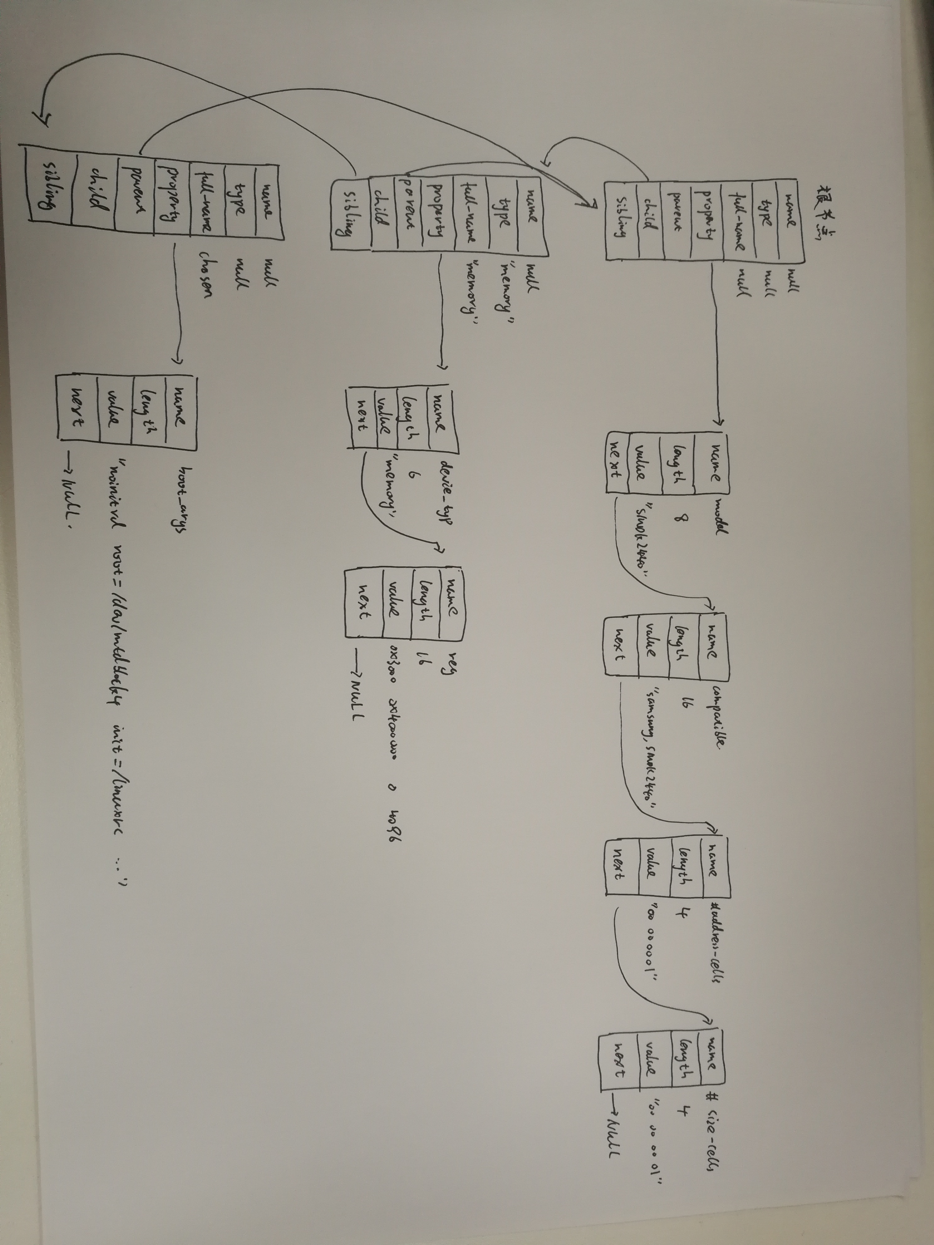
4.5 设备树与device_node ,property关系图
jz2440.dts源码
#define S3C2410_GPF(_nr)    ((5<<16) + (_nr))

/dts-v1/;

/ {

    model = "SMDK24440";

    compatible = "samsung,smdk2440";

    #address-cells = <>;

    #size-cells = <>;

    memory@

    {

        device_type = "memory";

        reg =  <0x30000000 0x4000000>;

    };

    chosen

    {

        bootargs = "noinitrd root=/dev/mtdblock4 rw init=/linuxrc console=ttySAC0,115200";

    };

    led

    {

        compatible = "jz2440_led";

        reg = <S3C2410_GPF() >;

    };

};
关系图:
4.6 device_node转换为platform_device
platform_device->device->device_node
a. 哪些device_node可以转换为platform_device?

根节点下含有compatile属性的子节点

如果一个结点的compatile属性含有这些特殊的值("simple-bus","simple-mfd","isa","arm,amba-bus")之一, 那么它的子结点(需含compatile属性)也可以转换为platform_device

i2c, spi等总线节点下的子节点, 应该交给对应的总线驱动程序来处理, 它们不应该被转换为platform_device

b. 怎么转换?

platform_device中含有resource数组, 它来自device_node的reg, interrupts属性,从device_node转换得到;

platform_device.dev.of_node指向device_node, 可以通过它获得其他属性

struct platform_device {

    const char    *name;

    int        id;

    bool        id_auto;

    struct device    dev;         // device->of_node(device_node) 保存device_node其他属性

    u32        num_resources;       // 资源数组有多少项

    struct resource    *resource;   // 资源数组(资源种类IO/MEM/INT)

};

b. 示例:

    比如以下的节点,

    /mytest会被转换为platform_device,

    因为它兼容"simple-bus", 它的子节点/mytest/mytest@ 也会被转换为platform_device

    /i2c节点一般表示i2c控制器, 它会被转换为platform_device, 在内核中有对应的platform_driver;

    /i2c/at24c02节点不会被转换为platform_device, 它被如何处理完全由父节点的platform_driver决定, 一般是被创建为一个i2c_client。

    类似的也有/spi节点, 它一般也是用来表示SPI控制器, 它会被转换为platform_device, 在内核中有对应的platform_driver;

    /spi/flash@0节点不会被转换为platform_device, 它被如何处理完全由父节点的platform_driver决定, 一般是被创建为一个spi_device。

    / {

          mytest {

              compatile = "mytest", "simple-bus";

              mytest@ {

                    compatile = "mytest_0";

              };

          };

          i2c {

              compatile = "samsung,i2c";

              at24c02 {

                    compatile = "at24c02";

              };

          };

          spi {

              compatile = "samsung,spi";

              flash@ {

                    compatible = "winbond,w25q32dw";

                    spi-max-frequency = <>;

                    reg = <>;

                  };

          };

      };

函数调用过程:

a. of_platform_default_populate_init (drivers/of/platform.c) 被调用到过程:

start_kernel     // init/main.c

    rest_init();

        pid = kernel_thread(kernel_init, NULL, CLONE_FS);

                    kernel_init

                        kernel_init_freeable();

                            do_basic_setup();

                                do_initcalls();

                                    for (level = ; level < ARRAY_SIZE(initcall_levels) - ; level++)

                                        do_initcall_level(level);  // 比如 do_initcall_level(3)

                                               for (fn = initcall_levels[]; fn < initcall_levels[+]; fn++)

                                                    do_one_initcall(initcall_from_entry(fn));  // 就是调用"arch_initcall_sync(fn)"中定义的fn函数

            常见GNU的attribite指定section机制

            arch_initcall_sync(of_platform_default_populate_init);

            #define arch_initcall_sync(fn)        __define_initcall(fn, 3s)

            #define __define_initcall(fn, id) ___define_initcall(fn, id, .initcall##id)

            #define ___define_initcall(fn, id, __sec) static initcall_t __initcall_##fn##id __used __attribute__((__section__(#__sec ".init"))) = fn;

b. of_platform_default_populate_init  (drivers/of/platform.c) 生成platform_device的过程:

of_platform_default_populate_init

    of_platform_default_populate(NULL, NULL, NULL);

        of_platform_populate(NULL, of_default_bus_match_table, NULL, NULL)        // 如果节点中含有of_default_bus_match_table的值之一,就为子节点创建platform_device

            for_each_child_of_node(root, child) {                                 // 便利整个device_node树,为特定的节点生成platform_device

                rc = of_platform_bus_create(child, matches, lookup, parent, true);// 创建总线

                            dev = of_device_alloc(np, bus_id, parent);            // 根据device_node节点的属性设置platform_device的resource

                                of_address_to_resource(np, i, res);               // address转资源

                                of_irq_to_resource_table(np, res, num_irq)        // 中断转资源

                if (rc) {

                    of_node_put(child);

                    break;

                }

            }

c. of_platform_bus_create(bus, matches, ...)的调用过程(处理bus节点生成platform_devie, 并决定是否处理它的子节点):

        dev = of_platform_device_create_pdata(bus, bus_id, platform_data, parent);  // 生成bus节点的platform_device结构体

        if (!dev || !of_match_node(matches, bus))  // 如果bus节点的compatile属性不吻合matches成表, 就不处理它的子节点

            return ;

        for_each_child_of_node(bus, child) {    // 取出每一个子节点

            pr_debug("   create child: %pOF\n", child);

            rc = of_platform_bus_create(child, matches, lookup, &dev->dev, strict);   // 处理它的子节点, of_platform_bus_create是一个递归调用

            if (rc) {

                of_node_put(child);

                break;

            }

        }

d. I2C总线节点的处理过程:

   /i2c节点一般表示i2c控制器, 它会被转换为platform_device, 在内核中有对应的platform_driver;

   platform_driver的probe函数中会调用i2c_add_numbered_adapter:

   i2c_add_numbered_adapter   // drivers/i2c/i2c-core-base.c

        __i2c_add_numbered_adapter

            i2c_register_adapter

                of_i2c_register_devices(adap);   // drivers/i2c/i2c-core-of.c

                    for_each_available_child_of_node(bus, node) {

                        client = of_i2c_register_device(adap, node);

                                        client = i2c_new_device(adap, &info);   // 设备树中的i2c子节点被转换为i2c_client

                    }

e. SPI总线节点的处理过程:

   /spi节点一般表示spi控制器, 它会被转换为platform_device, 在内核中有对应的platform_driver;

   platform_driver的probe函数中会调用spi_register_master, 即spi_register_controller:

   spi_register_controller        // drivers/spi/spi.c

        of_register_spi_devices   // drivers/spi/spi.c

            for_each_available_child_of_node(ctlr->dev.of_node, nc) {

                spi = of_register_spi_device(ctlr, nc);  // 设备树中的spi子节点被转换为spi_device

                                spi = spi_alloc_device(ctlr);

                                rc = of_spi_parse_dt(ctlr, spi, nc);

                                rc = spi_add_device(spi);

            }
5.1 内核中设备树的操作函数
dtb -> device_node -> platform_device

a. 处理DTB

of_fdt.h           // dtb文件的相关操作函数, 我们一般用不到, 因为dtb文件在内核中已经被转换为device_node树(它更易于使用)

b. 处理device_node

of.h               // 提供设备树的一般处理函数, 比如 of_property_read_u32(读取某个属性的u32值), of_get_child_count(获取某个device_node的子节点数)

of_address.h       // 地址相关的函数, 比如 of_get_address(获得reg属性中的addr, size值)

of_match_device(从matches数组中取出与当前设备最匹配的一项)

of_dma.h           // 设备树中DMA相关属性的函数

of_gpio.h          // GPIO相关的函数

of_graph.h         // GPU相关驱动中用到的函数, 从设备树中获得GPU信息

of_iommu.h         // 很少用到

of_irq.h           // 中断相关的函数

of_mdio.h          // MDIO (Ethernet PHY) API

of_net.h           // OF helpers for network devices.

of_pci.h           // PCI相关函数

of_pdt.h           // 很少用到

of_reserved_mem.h  // reserved_mem的相关函数

c. 处理 platform_device

of_platform.h      // 把device_node转换为platform_device时用到的函数,

                   // 比如of_device_alloc(根据device_node分配设置platform_device),

                   //     of_find_device_by_node (根据device_node查找到platform_device),

                   //     of_platform_bus_probe (处理device_node及它的子节点)

of_device.h        // 设备相关的函数, 比如 of_match_device
5.2 在根文件系统中查看设备树(有助于调试)
a. /sys/firmware/fdt        // 原始dtb文件

  hexdump -C /sys/firmware/fdt

b. /sys/firmware/devicetree // 以目录结构程现的dtb文件, 根节点对应base目录, 每一个节点对应一个目录, 每一个属性对应一个文件

c. /sys/devices/platform    // 系统中所有的platform_device, 有来自设备树的, 也有来有.c文件中注册的

   对于来自设备树的platform_device,

   可以进入 /sys/devices/platform/<设备名>/of_node 查看它的设备树属性

d.  /proc/device-tree 是链接文件, 指向 /sys/firmware/devicetree/base
6 u-boot 可以对设备树做些什么
6.1 uboot如何传递设备树给内核
a. u-boot中内核启动命令:

   bootm <uImage_addr>                            // 无设备树,bootm 0x30007FC0

   bootm <uImage_addr> <initrd_addr> <dtb_addr>   // 有设备树

   比如 :

   nand read.jffs2 0x30007FC0 kernel;     // 读内核uImage到内存0x30007FC0

   nand read.jffs2  device_tree;  // 读dtb到内存32000000

   bootm 0x30007FC0 - 0x32000000          // 启动, 没有initrd时对应参数写为"-"

b. bootm命令怎么把dtb_addr写入r2寄存器传给内核?

   ARM程序调用规则(ATPCS)

      c_function(p0, p1, p2) // p0 => r0, p1 => r1, p2 => r2

      定义函数指针 the_kernel, 指向内核的启动地址,

      然后执行: the_kernel(, machine_id, 0x32000000);

c. dtb_addr 可以随便选吗?

   c. 不要破坏u-boot本身

   c. 不要挡内核的路: 内核本身的空间不能占用, 内核要用到的内存区域也不能占用

                       内核启动时一般会在它所处位置的下边放置页表, 这块空间(一般是0x4000即16K字节)不能被占用

  JZ2440内存使用情况:

                     ------------------------------

  0x33f80000       ->|    u-boot                  |

                     ------------------------------

                     |    u-boot所使用的内存(栈等)|

                     ------------------------------

                     |                            |

                     |                            |

                     |        空闲区域            |

                     |                            |

                     |                            |

                     |                            |

                     |                            |

                     ------------------------------

  0x30008000       ->|      zImage                |

                     ------------------------------  uImage = 64字节的头部+zImage

  0x30007FC0       ->|      uImage头部            |

                     ------------------------------

  0x30004000       ->|      内核创建的页表        |  head.S

                     ------------------------------

                     |                            |

                     |                            |

              -----> ------------------------------

              |

              |

              --- (内存基址 0x30000000)

命令示例:

a. 可以启动:

nand read.jffs2  device_tree

nand read.jffs2 0x30007FC0 kernel

bootm 0x30007FC0 -

b. 不可以启动: 内核启动时会使用0x30004000的内存来存放页表,dtb会被破坏

nand read.jffs2  device_tree

nand read.jffs2 0x30007FC0 kernel

bootm 0x30007FC0 -
6.2 .dtb文件的修改原理
例子1. 修改属性的值,

假设 老值: len

     新值: newlen (假设newlen > len)

a. 把原属性val所占空间从len字节扩展为newlen字节:

   把老值之后的所有内容向后移动(newlen - len)字节

b. 把新值写入val所占的newlen字节空间

c. 修改dtb头部信息中structure block的长度: size_dt_struct

d. 修改dtb头部信息中string block的偏移值: off_dt_strings

e. 修改dtb头部信息中的总长度: totalsize

例子2. 添加一个全新的属性

a. 如果在string block中没有这个属性的名字,

   就在string block尾部添加一个新字符串: 属性的名

   并且修改dtb头部信息中string block的长度: size_dt_strings

   修改dtb头部信息中的总长度: totalsize

b. 找到属性所在节点, 在节点尾部扩展一块空间, 内容及长度为:

   TAG      // 4字节, 对应0x00000003

   len      // 4字节, 表示属性的val的长度

   nameoff  // 4字节, 表示属性名的offset

   val      // len字节, 用来存放val

c. 修改dtb头部信息中structure block的长度: size_dt_struct

d. 修改dtb头部信息中string block的偏移值: off_dt_strings

e. 修改dtb头部信息中的总长度: totalsize

可以从u-boot官网源码下载一个比较新的u-boot, 查看它的cmd/fdt.c

ftp://ftp.denx.de/pub/u-boot/


fdt命令集合:
"fdt move <fdt> <newaddr> <length> - Copy the fdt to <addr> and make it active\n"
"fdt resize [<extrasize>] - Resize fdt to size + padding to 4k addr + some optional <extrasize> if needed\n"
"fdt print <path> [<prop>] - Recursive print starting at <path>\n"
"fdt list <path> [<prop>] - Print one level starting at <path>\n"
"fdt get value <var> <path> <prop> - Get <property> and store in <var>\n"
"fdt get name <var> <path> <index> - Get name of node <index> and store in <var>\n"
"fdt get addr <var> <path> <prop> - Get start address of <property> and store in <var>\n"
"fdt get size <var> <path> [<prop>] - Get size of [<property>] or num nodes and store in <var>\n"
"fdt set <path> <prop> [<val>] - Set <property> [to <val>]\n"
"fdt mknode <path> <node> - Create a new node after <path>\n"
"fdt rm <path> [<prop>] - Delete the node or <property>\n"
"fdt header - Display header info\n"
"fdt bootcpu <id> - Set boot cpuid\n"
"fdt memory <addr> <size> - Add/Update memory node\n"
"fdt rsvmem print - Show current mem reserves\n"
"fdt rsvmem add <addr> <size> - Add a mem reserve\n"
"fdt rsvmem delete <index> - Delete a mem reserves\n"
"fdt chosen [<start> <end>] - Add/update the /chosen branch in the tree\n"
fdt命令调用过程:

    fdt set    <path> <prop> [<val>]
a. 根据path找到节点

b. 根据val确定新值长度newlen, 并把val转换为字节流

c. fdt_setprop

        c. fdt_setprop_placeholder       // 为新值在DTB中腾出位置

                 fdt_get_property_w     // 得到老值的长度 oldlen

                 fdt_splice_struct_       // 腾空间

                        fdt_splice_       // 使用memmove移动DTB数据, 移动(newlen-oldlen)

                        fdt_set_size_dt_struct  // 修改DTB头部, size_dt_struct

                        fdt_set_off_dt_strings  // 修改DTB头部, off_dt_strings

        c. memcpy(prop_data, val, len);        // 在DTB中存入新值
6.3 fdt命令的移植
我们仍然使用u-boot 1.1.,需要在里面添加fdc命令命令, 这个命令可以用来查看、修改dtb

从u-boot官网下载最新的源码, 把里面的 cmd/fdt.c移植过来.

u-boot官网源码:

ftp://ftp.denx.de/pub/u-boot/

  最终的补丁存放在如下目录: doc_and_sources_for_device_tree\source_and_images\u-boot\u-boot-1.1.6_device_tree_for_jz2440_add_fdt_20181022.patch

  补丁使用方法:

  export  PATH=PATH=/usr/local/sbin:/usr/local/bin:/usr/sbin:/usr/bin:/sbin:/bin:/usr/games:/work/system/gcc-linaro-4.9.-2017.01-x86_64_arm-linux-gnueabi/bin

  tar xjf u-boot-1.1..tar.bz2                                                // 解压

  cd u-boot-1.1.

  patch -p1 < ../u-boot-1.1.6_device_tree_for_jz2440_add_fdt_20181022.patch   // 打补丁

  make 100ask24x0_config                                                      // 配置

  make                                                                        // 编译, 可以得到u-boot.bin

a. 移植fdt命令

a. 先把代码移过去, 修改Makefile来编译

u-boot-2018.11-rc2\lib\libfdt   主要用这个目录,

                                它里面的大部分文件是直接包含scripts\dtc\libfdt中的同名文件

                                只有2个文件是自己的版本

u-boot-2018.11-rc2\scripts\dtc\libfdt

把新u-boot中cmd/fdt.c重命名为cmd_fdt.c , 和 lib/libfdt   // 一起复制到老u-boot的common/fdt目录

修改 老u-boot/Makefile, 添加一行: LIBS += common/fdt/libfdt.a

修改 老u-boot/common/fdt/Makefile, 仿照 drivers/nand/Makefile来修改

a. 根据编译的错误信息修改源码

移植时常见问题:

i. No such file or directory:

   要注意,

   #include "xxx.h"  // 是在当前目录下查找xxx.h

   #include <xxx.h>  // 是在指定目录下查找xxx.h, 哪些指定目录呢?

                     // 编译文件时可以用"-I"选项指定头文件目录,

                     // 比如: arm-linux-gcc -I <dir> -c -o ....

                     // 对于u-boot来说, 一般就是源码的 include目录

   解决方法:

   确定头文件在哪, 把它移到include目录或是源码的当前目录

ii. xxx undeclared :

   宏, 变量, 函数未声明/未定义

   对于宏, 去定义它;

   对于变量, 去定义它或是声明为外部变量;

   对于函数, 去实现它或是声明为外部函数;

iii. 上述2个错误是编译时出现的,

   当一切都没问题时, 最后就是链接程序, 这时常出现: undefined reference to `xxx'

   这表示代码里用到了xxx函数, 但是这个函数没有实现

   解决方法: 去实现它, 或是找到它所在文件, 把这文件加入工程

b. fdt命令使用示例

nand read.jffs2  device_tree  // 从flash读出dtb文件到内存(0x32000000)

fdt addr                      // 告诉fdt, dtb文件在哪

fdt print /led pin                    // 打印/led节点的pin属性

fdt get value XXX /led pin            // 读取/led节点的pin属性, 并且赋给环境变量XXX

print XXX                             // 打印环境变量XXX的值

fdt set /led pin <0x00050005>         // 设置/led节点的pin属性

fdt print /led pin                    // 打印/led节点的pin属性

nand erase device_tree                // 擦除flash分区

nand write.jffs2  device_tree // 把修改后的dtb文件写入flash分区
7.1 Linux对中断处理的框架及代码流程简述
a. 异常向量入口: arch\arm\kernel\entry-armv.S

    .section .vectors, "ax", %progbits

.L__vectors_start:

    W(b)    vector_rst

    W(b)    vector_und

    W(ldr)  pc, .L__vectors_start + 0x1000

    W(b)    vector_pabt

    W(b)    vector_dabt

    W(b)    vector_addrexcptn

    W(b)    vector_irq

    W(b)    vector_fiq

b. 中断向量: vector_irq

/*

 * Interrupt dispatcher

 */

    vector_stub irq, IRQ_MODE,    // 相当于 vector_irq: ...,

                                   // 它会根据SPSR寄存器的值,

                                   // 判断被中断时CPU是处于USR状态还是SVC状态,

                                   // 然后调用下面的__irq_usr或__irq_svc

    .long   __irq_usr               @    (USR_26 / USR_32)

    .long   __irq_invalid           @    (FIQ_26 / FIQ_32)

    .long   __irq_invalid           @    (IRQ_26 / IRQ_32)

    .long   __irq_svc               @    (SVC_26 / SVC_32)

    .long   __irq_invalid           @

    .long   __irq_invalid           @

    .long   __irq_invalid           @

    .long   __irq_invalid           @

    .long   __irq_invalid           @

    .long   __irq_invalid           @

    .long   __irq_invalid           @  a

    .long   __irq_invalid           @  b

    .long   __irq_invalid           @  c

    .long   __irq_invalid           @  d

    .long   __irq_invalid           @  e

    .long   __irq_invalid           @  f

c. __irq_usr/__irq_svc

    __irq_usr:

    usr_entry                  // 保存现场

    kuser_cmpxchg_check

    irq_handler                  // 调用 irq_handler

    get_thread_info tsk

    mov    why, #

    b    ret_to_user_from_irq   // 恢复现场

d. irq_handler: 将会调用C函数 handle_arch_irq

    .macro  irq_handler

#ifdef CONFIG_GENERIC_IRQ_MULTI_HANDLER

    ldr r1, =handle_arch_irq

    mov r0, sp

    badr    lr, 9997f

    ldr pc, [r1]

#else

    arch_irq_handler_default

#endif

:

    .endm

e. handle.c

   set_handle_irq( pointer_to_fun() )

        handle_arch_irq = pointer_to_fun()
f. handle_arch_irq的处理过程: (读取中断控制器得到硬件中断号,然后再找到中断控制器对应的域,在域里面从硬件中断号得到虚拟中断号,找到irq_desc[virq])
读取寄存器获得中断信息: hwirq
把hwirq转换为virq // hwirq为硬件中断号,virq为虚拟中断号 (两者间有偏移值)
// #define S3C2410_CPUIRQ_OFFSET (16) #define S3C2410_IRQ(x) ((x) + S3C2410_CPUIRQ_OFFSET)
调用 1.irq_desc[virq].handle_irq //处理中断
2.irq_desc[virq].irq_data.irq_chip.fun() // 清中断
对于S3C2440,irq_s3c24xx.c是入口源文件, s3c24xx_handle_irq 是用于处理中断的C语言入口函数
set_handle_irq(s3c24xx_handle_irq);
 注:

    irq_desc[nr_irqs]                  // 包含有多个irq_desc结构体,每个对应不同的中断

    struct irq_desc

    {

    struct irq_data        irq_data;     // 带有具体处理中断函数

    irq_flow_handler_t    handle_irq;   // 1.调用action链表中的handler(也就是具体的处理函数) 2.再清中断(使用irq_data->chip的函数)

    struct irqaction    *action;      // 指向irqaction链表

    }

    struct irqaction

    {

    irq_handler_t        handler;      // 用户设置的中断的具体处理函数

    void                *dev_id;      // request_irq(unsigned int irq, irq_handler_t handler, unsigned long flags,const char *name, void *dev)
struct irqaction    *next;
    }

    struct irq_data

    {

    u32            mask;

    unsigned int        irq;

    unsigned long        hwirq;

    struct irq_common_data    *common;

    struct irq_chip        *chip;        // 很多中断操作函数

    struct irq_domain    *domain;

    void            *chip_data;

    };

    struct irq_chip

    {

    void    (*irq_enable)(struct irq_data *data);   // 使能中断函数

    void    (*irq_disable)(struct irq_data *data);  // 去使能中断函数

    void    (*irq_ack)(struct irq_data *data);

    void    (*irq_mask)(struct irq_data *data);        //屏蔽中断函数

    void    (*irq_unmask)(struct irq_data *data);

    }
中断处理流程:
假设中断结构如下:
sub int controller ---> int controller ---> cpu
发生中断时,
cpu跳到"vector_irq", 保存现场, 调用C函数handle_arch_irq
handle_arch_irq:
a. 读 int controller, 得到hwirq
b. 根据hwirq得到virq
c. 调用 irq_desc[virq].handle_irq
如果该中断没有子中断, irq_desc[virq].handle_irq的操作:
a. 取出irq_desc[virq].action链表中的每一个handler, 执行它
b. 使用irq_desc[virq].irq_data.chip的函数清中断
如果该中断是由子中断产生, irq_desc[virq].handle_irq的操作:
a. 读 sub int controller, 得到hwirq'
b. 根据hwirq'得到virq
c. 调用 irq_desc[virq].handle_irq
调用过程:
s3c24xx_handle_intc
pnd = readl_relaxed(intc->reg_intpnd);
handle_domain_irq(intc->domain, intc_offset + offset, regs);
__handle_domain_irq(domain, hwirq, true, regs);
irq = irq_find_mapping(domain, hwirq);
generic_handle_irq(irq);
struct irq_desc *desc = irq_to_desc(irq);
generic_handle_irq_desc(desc);
desc->handle_irq(desc);
7.2 中断号与domain域
不同的中断控制器对应不同的域,各个域的转换公式 不一样,防止不同硬件中断对应同一虚拟中断号(hwirq-->virq)
老中断体系,怎么使用中断

以前, 对于每一个硬件中断(hwirq)都预先确定它的中断号(virq),

这些中断号一般都写在一个头文件里, 比如arch\arm\mach-s3c24xx\include\mach\irqs.h

使用时,

a. 执行 request_irq(virq, my_handler) :

   内核根据virq可以知道对应的硬件中断, 然后去设置、使能中断等

b. 发生硬件中断时,

   内核读取硬件信息, 确定hwirq, 反算出virq,

   然后调用 irq_desc[virq].handle_irq, 最终会用到my_handler

怎么根据hwirq计算出virq?

硬件上有多个intc(中断控制器),

对于同一个hwirq数值, 会对应不同的virq

所以在讲hwirq时,应该强调"是哪一个intc的hwirq",

在描述hwirq转换为virq时, 引入一个概念: irq_domain, 域, 在这个域里hwirq转换为某一个virq

当中断控制器越来越多、当中断越来越多,上述方法(virq和hwirq固定绑定)有缺陷:

a. 增加工作量, 你需要给每一个中断确定它的中断号, 写出对应的宏, 可能有成百上千个

b. 你要确保每一个硬件中断对应的中断号互不重复

有什么方法改进?

a. hwirq跟virq之间不再绑定

b. 要使用某个hwirq时,

   先在irq_desc数组中找到一个空闲项, 它的位置就是virq

   再在irq_desc[virq]中放置处理函数

新中断体系中, 怎么使用中断:

a.以前是request_irq发起,

  现在是先在设备树文件中声明想使用哪一个中断(哪一个中断控制器下的哪一个中断)

b. 内核解析设备树时,

   会根据"中断控制器"确定irq_domain,

   根据"哪一个中断"确定hwirq,

   然后在irq_desc数组中找出一个空闲项, 它的位置就是virq

   并且把virq和hwirq的关系保存在irq_domain中: irq_domain.linear_revmap[hwirq] = virq;

c. 驱动程序 request_irq(virq, my_handler)

d. 发生硬件中断时,

内核读取硬件信息, 确定hwirq, 确定中断控制器的域,确定 virq =  irq_domain.linear_revmap[hwirq];

然后调用 irq_desc[virq].handle_irq, 最终会用到my_handler

假设要使用子中断控制器(subintc)的n号中断, 它发生时会导致父中断控制器(intc)的m号中断:

a. 设备树表明要使用<subintc n>

   subintc表示要使用<intc m>

b. 解析设备树时,

   会为<subintc n>找到空闲项 irq_desc[virq'], sub irq_domain.linear_revmap[n] = virq';

   会为<intc m>   找到空闲项 irq_desc[virq], irq_domain.linear_revmap[m] = virq;

   并且设置它的handle_irq为某个分析函数demux_func

c. 驱动程序 request_irq(virq', my_handler)

d. 发生硬件中断时,

内核读取intc硬件信息, 确定hwirq = m, 确定 virq =  irq_domain.linear_revmap[m];

然后调用 irq_desc[m].handle_irq, 即demux_func

e. demux_func:

读取sub intc硬件信息, 确定hwirq = n, 确定 virq' =  sub irq_domain.linear_revmap[n];

然后调用 irq_desc[n].handle_irq, 即my_handler

在设备树中设置中断控制器和硬件中断号,内核才会生成虚拟中断号。<intcxx,hwirqxx> --> virq
.xlate (解析设备树,得到hwirq,irq_type)
.map    (hwirq <--> virq)建立联系
7.3 设备树如何描述中断
  make uImage   // 生成 arch/arm/boot/uImage

  make dtbs     // 生成 arch/arm/boot/dts/jz2440_irq.dtb

老内核:

/ # cat /proc/interrupts

           CPU0

 :             s3c   Edge      samsung_time_irq

 :                 s3c   Edge      ohci_hcd:usb1

 :                 s3c   Edge      s3c2440-i2c.

 :           s3c-level    Edge      s3c2440-uart

 :          s3c-level    Edge      s3c2440-uart

 :            s3c-level    Edge      ts_pen

 :            s3c-level   Edge      adc

 :            s3c-level   Edge      s3c2410-wdt

新内核:

nfs  192.168.1.124:/work/nfs_root/uImage; nfs  192.168.1.124:/work/nfs_root/jz2440_irq.dtb; bootm  -

/ # cat /proc/interrupts

           CPU0

  :                 s3c    Edge      s3c2410-rtc tick

 :               s3c   Edge      samsung_time_irq

 :                 s3c   Edge      s3c2410-rtc alarm

 :           s3c-level   Level     .serial

 :           s3c-level   Level     .serial

 :            s3c-level   Edge      .watchdog

a. 某个设备要使用中断, 需要在设备树中描述中断, 如何?

   它要用哪一个中断? 这个中断连接到哪一个中断控制器去?

   即: 使用哪一个中断控制器的哪一个中断?

   至少有有2个属性:

   interrupts        // 表示要使用哪一个中断, 中断的触发类型等等

   interrupt-parent  // 这个中断要接到哪一个设备去? 即父中断控制器是谁

b. 上述的interrupts属性用多少个u32来表示?

   这应该由它的父中断控制器来描述,

   在父中断控制器中, 至少有2个属性:

   interrupt-controller;   // 表示自己是一个中断控制器

    #interrupt-cells       // 表示自己的子设备里应该有几个U32的数据来描述中断

c.  如何用设备树描述一个中断                        --> (ethernet@)

    .表明这个中断属于哪个中断控制器                 --> interrupt_parent = intc

    .表明这个中断属于中断控制器的哪个中断            --> interrupts = < intc_num  [trigger_type] >

                                                        具体含义,用多少个U32描述,由中断控制器解释

d.  如何用设备树描述二级中断控制器                   -->(gpg)(gpf)

    .表明这是一个中断控制器                        --> interrup_controller;

    .表明控制器下一级中断要用多少U32描述下级中断      -->#interrupt-cells = <0x4>

    .表明这个中断控制器的上一级中断控制器            --> phandle = <0x6>

e.  根节点下如何描述中断                            -->(/{)

    interrupt-parent = <0x1>

f.  如何用设备树描述一级中断控制器                   -->(interrupt-controller@4a000000)

    .表明控制器下一级中断要用多少U32描述下级中断      -->#interrupt-cells = <0x4>

    .表明这是一个中断控制器                        --> interrup_controller;

    .表明他没有父节点                             --> phandle = <0x1>
jz2440_irq_all.dts 源码
/dts-v1/;

/ {

    compatible = "samsung,s3c2440", "samsung,smdk2440";

    interrupt-parent = <0x1>;

    #address-cells = <0x1>;

    #size-cells = <0x1>;

    model = "JZ2440";

    aliases {

        pinctrl0 = "/pinctrl@56000000";

        serial0 = "/serial@50000000";

        serial1 = "/serial@50004000";

        serial2 = "/serial@50008000";

        i2c1 = "/i2c-gpio-1";

    };

    interrupt-controller@4a000000 {

        compatible = "samsung,s3c2410-irq";

        reg = <0x4a000000 0x100>;

        interrupt-controller;

        #interrupt-cells = <0x4>;

        phandle = <0x1>;

    };

    pinctrl@ {

        reg = <0x56000000 0x1000>;

        compatible = "samsung,s3c2440-pinctrl";

        wakeup-interrupt-controller {

            compatible = "samsung,s3c2410-wakeup-eint";

            interrupts = <0x0 0x0 0x0 0x3 0x0 0x0 0x1 0x3 0x0 0x0 0x2 0x3 0x0 0x0 0x3 0x3 0x0 0x0 0x4 0x4 0x0 0x0 0x5 0x4>;

        };

        gpa {

            gpio-controller;

            #gpio-cells = <0x2>;

        };

        gpb {

            gpio-controller;

            #gpio-cells = <0x2>;

            phandle = <0xd>;

        };

        gpc {

            gpio-controller;

            #gpio-cells = <0x2>;

        };

        gpd {

            gpio-controller;

            #gpio-cells = <0x2>;

        };

        gpe {

            gpio-controller;

            #gpio-cells = <0x2>;

            phandle = <0x7>;

        };

        gpf {

            gpio-controller;

            #gpio-cells = <0x2>;

            interrupt-controller;

            #interrupt-cells = <0x2>;

            phandle = <0x6>;

        };

        gpg {

            gpio-controller;

            #gpio-cells = <0x2>;

            interrupt-controller;

            #interrupt-cells = <0x2>;

        };

        gph {

            gpio-controller;

            #gpio-cells = <0x2>;

        };

        gpj {

            gpio-controller;

            #gpio-cells = <0x2>;

        };

        uart0-data {

            samsung,pins = "gph-0", "gph-1";

            samsung,pin-function = <0x2>;

            phandle = <0x3>;

        };

        i2c0-bus {

            samsung,pins = "gpe-14", "gpe-15";

            samsung,pin-function = <0x2>;

            phandle = <0x4>;

        };

        nand_pinctrl {

            samsung,pins = "gpa-17", "gpa-18", "gpa-19", "gpa-20", "gpa-22";

            samsung,pin-function = <0x1>;

            phandle = <0x5>;

        };

        lcd_pinctrl {

            samsung,pins = "gpc-8", "gpc-9", "gpc-10", "gpc-11", "gpc-12", "gpc-13", "gpc-14", "gpc-15", "gpd-0", "gpd-1", "gpd-2", "gpd-3", "gpd-4", "gpd-5", "gpd-6", "gpd-7", "gpd-8", "gpd-9", "gpd-10", "gpd-11", "gpd-12", "gpd-13", "gpd-14", "gpd-15", "gpc-1", "gpc-2", "gpc-3", "gpc-4";

            samsung,pin-function = <0x2>;

            phandle = <0x8>;

        };

        lcd_backlight {

            samsung,pins = "gpg-4";

            samsung,pin-function = <0x3>;

            phandle = <0x9>;

        };

        uda1340_codec_pinctrl {

            samsung,pins = "gpb-4", "gpb-3", "gpb-2";

            samsung,pin-function = <0x1>;

            phandle = <0xc>;

        };

        s3c2440_iis_pinctrl {

            samsung,pins = "gpe-0", "gpe-1", "gpe-2", "gpe-3", "gpe-4";

            samsung,pin-function = <0x2>;

            phandle = <0xa>;

        };

    };

    timer@ {

        compatible = "samsung,s3c2410-pwm";

        reg = <0x51000000 0x1000>;

        interrupts = <0x0 0x0 0xa 0x3 0x0 0x0 0xb 0x3 0x0 0x0 0xc 0x3 0x0 0x0 0xd 0x3 0x0 0x0 0xe 0x3>;

        #pwm-cells = <0x4>;

        clock-names = "timers";

        clocks = <0x2 0x19>;

    };

    serial@ {

        compatible = "samsung,s3c2440-uart";

        reg = <0x50000000 0x4000>;

        interrupts = <0x1 0x1c 0x0 0x4 0x1 0x1c 0x1 0x4>;

        status = "okay";

        clock-names = "uart";

        clocks = <0x2 0x10>;

        pinctrl-names = "default";

        pinctrl- = <0x3>;

    };

    serial@ {

        compatible = "samsung,s3c2410-uart";

        reg = <0x50004000 0x4000>;

        interrupts = <0x1 0x17 0x3 0x4 0x1 0x17 0x4 0x4>;

        status = "disabled";

    };

    serial@ {

        compatible = "samsung,s3c2410-uart";

        reg = <0x50008000 0x4000>;

        interrupts = <0x1 0xf 0x6 0x4 0x1 0xf 0x7 0x4>;

        status = "disabled";

    };

    watchdog@ {

        compatible = "samsung,s3c2410-wdt";

        reg = <0x53000000 0x100>;

        interrupts = <0x1 0x9 0x1b 0x3>;

        status = "okay";

        clocks = <0x2 0x6>;

        clock-names = "watchdog";

    };

    rtc@ {

        compatible = "samsung,s3c2410-rtc";

        reg = <0x57000000 0x100>;

        interrupts = <0x0 0x0 0x1e 0x3 0x0 0x0 0x8 0x3>;

        status = "okay";

        clocks = <0x2 0x1a>;

        clock-names = "rtc";

    };

    i2c@ {

        compatible = "samsung,s3c2440-i2c";

        reg = <0x54000000 0x100>;

        interrupts = <0x0 0x0 0x1b 0x3>;

        #address-cells = <0x1>;

        #size-cells = <0x0>;

        status = "disabled";

        clocks = <0x2 0x13>;

        clock-names = "i2c";

        pinctrl-names = "default";

        pinctrl- = <0x4>;

    };

    cpus {

        #address-cells = <0x1>;

        #size-cells = <0x0>;

        cpu {

            compatible = "arm,arm920t";

        };

    };

    xti_clock {

        compatible = "fixed-clock";

        clock-frequency = <0xb71b00>;

        clock-output-names = "xti";

        #clock-cells = <0x0>;

    };

    clock-controller@4c000000 {

        compatible = "samsung,s3c2440-clock";

        reg = <0x4c000000 0x20>;

        #clock-cells = <0x1>;

        phandle = <0x2>;

    };

    nand@4e000000 {

        compatible = "samsung,s3c2440-nand";

        reg = <0x4e000000 0x40>;

        interrupts = <0x0 0x0 0x18 0x3>;

        clocks = <0x2 0x23>;

        clock-names = "nand";

        pinctrl-names = "default";

        pinctrl- = <0x5>;

        status = "okay";

        nand,tacls = <0xa>;

        nand,twrph0 = <0x19>;

        nand,twrph1 = <0xa>;

        #address-cells = <0x1>;

        #size-cells = <0x1>;

        partitions {

            #address-cells = <0x1>;

            #size-cells = <0x1>;

            nr-chips = <0x1>;

            set-name = "jz2440-0";

            partition@ {

                label = "bootloader";

                reg = <0x0 0x40000>;

                read-only;

            };

            partition@ {

                label = "device_tree";

                reg = <0x40000 0x20000>;

                read-only;

            };

            partition@ {

                label = "params";

                reg = <0x60000 0x20000>;

                read-only;

            };

            partition@ {

                label = "kernel";

                reg = <0x80000 0x400000>;

                read-only;

            };

            partition@ {

                label = "rootfs";

                reg = <0x480000 0x0>;

            };

        };

    };

    usb_ohci@ {

        compatible = "samsung,s3c2440-ohci";

        reg = <0x49000000 0x60>;

        interrupts = <0x0 0x0 0x1a 0x3>;

        clocks = <0x2 0x21 0x2 0x7>;

        clock-names = "usb-host", "usb-bus-host";

        status = "okay";

    };

    memory {

        device_type = "memory";

        reg = <0x30000000 0x4000000>;

    };

    chosen {

        bootargs = "noinitrd root=/dev/mtdblock4 rw init=/linuxrc console=ttySAC0,115200";

    };

    srom-cs4@ {

        compatible = "simple-bus";

        #address-cells = <0x1>;

        #size-cells = <0x1>;

        reg = <0x20000000 0x8000000>;

        ranges;

        ethernet@ {

            compatible = "davicom,dm9000";

            reg = <0x20000000 0x2 0x20000004 0x2>;

            interrupt-parent = <0x6>;

            interrupts = <0x7 0x1>;

            local-mac-address = [  de ad be ef];

            davicom,no-eeprom;

        };

    };

    i2c-gpio- {

        compatible = "i2c-gpio";

        #address-cells = <0x1>;

        #size-cells = <0x0>;

        gpios = <0x7 0xf 0x0 0x7 0xe 0x0>;

        i2c-gpio,delay-us = <0x5>;

        status = "disabled";

        eeprom@ {

            compatible = "24c02";

            reg = <0x50>;

            pagesize = <0x20>;

            status = "okay";

        };

    };

    fb@4d000000 {

        compatible = "jz2440,lcd";

        reg = <0x4d000000 0x60>;

        interrupts = <0x0 0x0 0x10 0x3>;

        clocks = <0x2 0x20>;

        clock-names = "lcd";

        pinctrl-names = "default";

        pinctrl- = <0x8 0x9>;

        status = "okay";

        lcdcon5 = <0xb09>;

        type = <0x60>;

        width = [ e0];

        height = [ ];

        pixclock = <0x186a0>;

        xres = [ e0];

        yres = [ ];

        bpp = [ ];

        left_margin = [ ];

        right_margin = [ ];

        hsync_len = [ ];

        upper_margin = [ ];

        lower_margin = [ ];

        vsync_len = [ 0a];

    };

    jz2440ts@ {

        compatible = "jz2440,ts";

        reg = <0x58000000 0x100>;

        reg-names = "adc_ts_physical";

        interrupts = <0x1 0x1f 0x9 0x3 0x1 0x1f 0xa 0x3>;

        interrupt-names = "int_ts", "int_adc_s";

        clocks = <0x2 0x16>;

        clock-names = "adc";

    };

    s3c2410-dma@4B000000 {

        compatible = "s3c2440-dma";

        reg = <0x4b000000 0x1000>;

        interrupts = <0x0 0x0 0x11 0x3 0x0 0x0 0x12 0x3 0x0 0x0 0x13 0x3 0x0 0x0 0x14 0x3>;

        #dma-cells = <0x1>;

        phandle = <0xb>;

    };

    s3c2440_iis@ {

        compatible = "s3c24xx-iis";

        reg = <0x55000000 0x100>;

        clocks = <0x2 0x18>;

        clock-names = "iis";

        pinctrl-names = "default";

        pinctrl- = <0xa>;

        dmas = <0xb 0x9 0xb 0xa>;

        dma-names = "rx", "tx";

    };

    s3c24xx_uda134x {

        compatible = "s3c24xx_uda134x";

        clocks = <0x2 0x2 0x2 0x18>;

        clock-names = "mpll", "iis";

    };

    uda134x-codec {

        compatible = "uda134x-codec";

        pinctrl-names = "default";

        pinctrl- = <0xc>;

        uda,clk_gpio = <0xd 0x4 0x1>;

        uda,data_gpio = <0xd 0x3 0x1>;

        uda,mode_gpio = <0xd 0x2 0x1>;

        uda,use_gpios;

        uda,data_hold;

        uda,data_setup;

        uda,clock_high;

        uda,mode_hold;

        uda,mode;

        uda,mode_setup;

        uda,model = <0x2>;

    };

};
7.4 按键中断设备树节点:
    buttons

    {

        compatible = "jz2440_button";

        eint-pins  = <&gpf  >, <&gpf  >, <&gpg  >, <&gpg  >;

        interrupts-extended = <&intc    >,<&intc    >, <&gpg  >, <&gpg  >;

    };

.  interrupts-extended (扩展中断属性):

    见:devicetree-specifications-v0. - 2.4.1节

    interrupt-extend = <&intc    >  --> &intc表示中断控制器      表示描述的是哪个中断

       3意义见:kernel/../samsung,s3c24xx-irq.txt:

                        <ctrl_num parent_irq ctrl_irq type>

                        val_1:ctrl_num contains the controller to use:(代表中断信号发给主还是子中断控制器)

                                -  ... main controller

                                -  ... sub controller

                                -  ... second main controller on s3c2416 and s3c2450

                        val_2: parent_irq contains the parent bit in the main controller and

                                    will be ignored in main controllers (代表子中断控制器是主中断控制器的中断)

                        val_3: ctrl_irq contains the interrupt bit of the controller(代表哪个中断)EINT0 EINT2

                        val_4: type contains the trigger type to use(中断的触发方式)

                                    trigger type见kernel\..\samsung-pinctrl.txt

                                        -  = rising edge triggered

                                        -  = falling edge triggered

                                        -  = rising and falling edge triggered

                                        -  = high level triggered

                                        -  = low level triggered

    <&gpg  > 见:kernel\..\samsung-pinctrl.txt

                        - First Cell: represents the external gpio interrupt number local to the (代表哪个中断)EINT3 EINT11

                                      external gpio interrupt space of the controller.

                        - Second Cell: flags to identify the type of the interrupt(代表中断触发方式)

                                        -  = rising edge triggered

                                        -  = falling edge triggered

                                        -  = rising and falling edge triggered

                                        -  = high level triggered

                                        -  = low level triggered
7.5内核对设备树中断信息的处理过程
从硬件结构上看, 处理过程分上下两个层面: 中断控制器, 使用中断的设备

从软件结构上看, 处理过程分左右两个部分: 在设备树中描述信息, 在驱动中处理设备树

中断分为三级

() 一级中断控制器   -->root_intc

这又分为root irq controller

a. root irq controller

a. 在设备树中的描述

a. 在内核中的驱动

()二级中断控制器    -->pinctrl

b. gpf/gpg irq controller

b. 在设备树中的描述(在pinctrl节点里)

b. 在内核中的驱动 (在pinctrl驱动中)

() 三级 设备的中断  -->按键中断

a. 在设备节点中描述(表明使用"哪一个中断控制器里的哪一个中断, 及中断触发方式")

a. 在内核中的驱动 (在platform_driver.probe中获得IRQ资源, 即中断号)

irq_domain是核心:
        {
           .ops.map   // 为硬件中断号  虚拟中断号创建联系
                    1.对于直达root_irq_control的中断,设置irq_desc[virq].handler_irq = handle_edeg_irq
                    2.对于先到达gpf_irq_control(virq_m),再到达root_irq_control(virq_n)的中断, 设置
                          先:irq_desc[virq_m].handler_irq = irq_demux(分发函数,需要读寄存器确定是哪个子中断产生,然后调用对应的handle_irq)
                          再:irq_desc[virq_n].handler_irq = handle_edeg_irq
           .ops.xlate  //解析设备树的中断信息,生成platform_device
           .linear_revmap[hwirq]=virq  // 将硬件中断号转化为虚拟中断号
        }

a. 每一个中断控制器都有一个irq_domain

b. 对设备中断信息的解析,

b. 需要调用 irq_domain->ops->xlate (即从设备树中获得hwirq, type)

b. 获取未使用的virq, 保存: irq_domain->linear_revmap[hwirq] = virq;

b. 在hwirq和virq之间建立联系:

   要调用 irq_domain->ops->map, 比如根据hwirq的属性设置virq的中断处理函数(是一个分发函数还是可以直接处理中断)

        irq_desc[virq].handle_irq = 常规函数;

   如果这个hwirq有上一级中断, 假设它的中断号为virq', 还要设置:

        irq_desc[virq'].handle_irq = 中断分发函数;

s3c2440设备树中断相关代码调用关系:

() 上述处理过程如何触发?

a. 内核启动时初始化中断的入口:

start_kernel // init/main.c

    init_IRQ();

        if (IS_ENABLED(CONFIG_OF) && !machine_desc->init_irq)

            irqchip_init();   // 一般使用它

        else

            machine_desc->init_irq();

b. 设备树中的中断控制器的处理入口:

irqchip_init // drivers/irqchip/irqchip.c

    of_irq_init(__irqchip_of_table);  // 对设备树文件中每一个中断控制器节点, 调用对应的处理函数

        为每一个符合的"interrupt-controller"节点,

        分配一个of_intc_desc结构体, desc->irq_init_cb = match->data; // = IRQCHIP_DECLARE中传入的函数

        并调用处理函数

        (先调用root irq controller对应的函数, 再调用子控制器的函数, 再调用更下一级控制器的函数...)

() root irq controller的中断控制器初始化过程:

a. 为root irq controller定义处理函数:

IRQCHIP_DECLARE(s3c2410_irq, "samsung,s3c2410-irq", s3c2410_init_intc_of);  //drivers/irqchip/irq-s3c24xx.c

其中:

#define IRQCHIP_DECLARE(name, compat, fn) OF_DECLARE_2(irqchip, name, compat, fn)

#define OF_DECLARE_2(table, name, compat, fn) \

        _OF_DECLARE(table, name, compat, fn, of_init_fn_2)

#define _OF_DECLARE(table, name, compat, fn, fn_type)           \

    static const struct of_device_id __of_table_##name      \

        __used __section(__##table##_of_table)          \

         = { .compatible = compat,              \

             .data = (fn == (fn_type)NULL) ? fn : fn  }

展开为:

    static const struct of_device_id __of_table_s3c2410_irq     \

        __used __section("__irqchip_of_table")          \

         = { .compatible = "samsung,s3c2410-irq",               \

             .data = s3c2410_init_intc_of  }

它定义了一个of_device_id结构体, 段属性为"__irqchip_of_table", 在编译内核时这些段被放在__irqchip_of_table地址处。

即__irqchip_of_table起始地址处,

放置了一个或多个 of_device_id, 它含有compatible成员;

设备树中的设备节点含有compatible属性,

如果双方的compatible相同, 并且设备节点含有"interrupt-controller"属性,

则调用of_device_id中的函数来处理该设备节点。

所以: IRQCHIP_DECLARE 是用来声明设备树中的中断控制器的处理函数。

b. root irq controller处理函数的执行过程:

s3c2410_init_intc_of  // drivers/irqchip/irq-s3c24xx.c

    // 初始化中断控制器: intc, subintc

    s3c_init_intc_of(np, interrupt_parent, s3c2410_ctrl, ARRAY_SIZE(s3c2410_ctrl));

        // 为中断控制器创建irq_domain

        domain = irq_domain_add_linear(np, num_ctrl * ,

                                 &s3c24xx_irq_ops_of, NULL);

        intc->domain = domain;

        // 设置handle_arch_irq, 即中断处理的C语言总入口函数

        set_handle_irq(s3c24xx_handle_irq);

() pinctrl系统中gpf/gpg irq controller的驱动调用过程:

a. pinctrl系统的中断控制器初始化过程:

a. 源代码: drivers/pinctrl/samsung/pinctrl-samsung.c

static struct platform_driver samsung_pinctrl_driver = {

    .probe      = samsung_pinctrl_probe,

    .driver = {

        .name   = "samsung-pinctrl",

        .of_match_table = samsung_pinctrl_dt_match, // 含有 { .compatible = "samsung,s3c2440-pinctrl", .data = &s3c2440_of_data },

        .suppress_bind_attrs = true,

        .pm = &samsung_pinctrl_pm_ops,

    },

};

a. 设备树中:

pinctrl@ {

    reg = <0x56000000 0x1000>;

    compatible = "samsung,s3c2440-pinctrl";  // 据此找到驱动

a. 驱动中的操作:

samsung_pinctrl_probe  // drivers/pinctrl/samsung/pinctrl-samsung.c

    最终会调用到 s3c24xx_eint_init // drivers/pinctrl/samsung/pinctrl-s3c24xx.c

        // eint0,1,2,3的处理函数在处理root irq controller时已经设置;

        // 设置eint4_7, eint8_23的处理函数(它们是分发函数)

        for (i = ; i < NUM_EINT_IRQ; ++i) {

            unsigned int irq;

            if (handlers[i]) /* add by weidongshan@qq.com, 不再设置eint0,1,2,3的处理函数 */

            {

                irq = irq_of_parse_and_map(eint_np, i);

                if (!irq) {

                    dev_err(dev, "failed to get wakeup EINT IRQ %d\n", i);

                    return -ENXIO;

                }

                eint_data->parents[i] = irq;

                irq_set_chained_handler_and_data(irq, handlers[i], eint_data);

            }

        }

        // 为GPF、GPG设置irq_domain

        for (i = ; i < d->nr_banks; ++i, ++bank) {

            ops = (bank->eint_offset == ) ? &s3c24xx_gpf_irq_ops

                               : &s3c24xx_gpg_irq_ops;

            bank->irq_domain = irq_domain_add_linear(bank->of_node, bank->nr_pins, ops, ddata);

        }

() 使用中断的驱动初始化过程:

a. 在设备节点中描述(表明使用"哪一个中断控制器里的哪一个中断, 及中断触发方式")

比如:

    buttons {

        compatible = "jz2440_button";

        eint-pins  = <&gpf  >, <&gpf  >, <&gpg  >, <&gpg  >;

        interrupts-extended = <&intc    >,

                              <&intc    >,

                              <&gpg  >,

                              <&gpg  >;

    };

b. 设备节点会被转换为 platform_device,

   "中断的硬件信息" 会转换为"中断号",

   保存在platform_device的"中断资源"里

   第3课第05节_device_node转换为platform_device, 讲解了设备树中设备节点转换为 platform_device 的过程;

   我们只关心里面对中断信息的处理:

of_device_alloc (drivers/of/platform.c)

    dev = platform_device_alloc("", PLATFORM_DEVID_NONE);  // 分配 platform_device

    num_irq = of_irq_count(np);  // 计算中断数

    of_irq_to_resource_table(np, res, num_irq) // drivers/of/irq.c, 根据设备节点中的中断信息, 构造中断资源

        of_irq_to_resource

            int irq = of_irq_get(dev, index);  // 获得virq, 中断号

                            rc = of_irq_parse_one(dev, index, &oirq); // drivers/of/irq.c, 解析设备树中的中断信息, 保存在of_phandle_args结构体中

                            domain = irq_find_host(oirq.np);   // 查找irq_domain, 每一个中断控制器都对应一个irq_domain

                            irq_create_of_mapping(&oirq);             // kernel/irq/irqdomain.c, 创建virq和中断信息的映射

                                irq_create_fwspec_mapping(&fwspec);

                                    irq_create_fwspec_mapping(&fwspec);

                                        irq_domain_translate(domain, fwspec, &hwirq, &type) // 调用irq_domain->ops->xlate, 把设备节点里的中断信息解析为hwirq, type

                                        virq = irq_find_mapping(domain, hwirq); // 看看这个hwirq是否已经映射, 如果virq非0就直接返回

                                        virq = irq_create_mapping(domain, hwirq); // 否则创建映射

                                                    virq = irq_domain_alloc_descs(-, , hwirq, of_node_to_nid(of_node), NULL);  // 返回未占用的virq

                                                    irq_domain_associate(domain, virq, hwirq) // 调用irq_domain->ops->map(domain, virq, hwirq), 做必要的硬件设置

c. 驱动程序从platform_device的"中断资源"取出中断号, 就可以request_irq()
8.3设备树的clock
文档:

内核 Documentation/devicetree/bindings/clock/clock-bindings.txt

内核 Documentation/devicetree/bindings/clock/samsung,s3c2410-clock.txt

s3c2440时钟:

                                                        FCLK    (cpu内核时钟)

INPUT_CLOCK->MPLL->CLOCK_DIVN->CLOCK_CON->CLOCK_SLOW->  HCLK    (AHB总线时钟) DMA NAND SDRAM

                                                        PCKL     (PHB总线时钟) PWM ADC GPIO UART

a.     设备树中一级时钟(MPLL),在文档中称之为"Clock providers", 比如:

    xti_clock

    {

        compatible = "fixed-clock";      //根据compatible,找到对应函数设置时钟为0xb71b00

        clock-frequency = <0xb71b00>;

        clock-output-names = "xti";

        #clock-cells = <0x0>;

    };

b. 设备树中二级时钟(FCLK,HCLK,PCLK), 在文档中称之为"Clock providers", 比如:

    clocks: clock-controller@4c000000

    {

        compatible = "samsung,s3c2440-clock"; //根据ccompatible,找到函数,通过reg寄存器设置时钟,并为每个子设备分配一个ID

        reg = <0x4c000000 0x20>;

        #clock-cells = <>;      // 想使用这个clocks时要表明设备是这个时钟的哪个子设备(ID)用32位来表示, 比如这个clocks中发出的LCD时钟、PWM时钟,NAND时钟

    };

c. 设备树中三级时钟(AHB/PHB总线上的设备),它是"Clock consumers", 它描述了使用哪一个"Clock providers"中的哪一个时钟(id), 比如:

    fb0: fb@4d000000

    {

        compatible = "jz2440,lcd";

        reg = <0x4D000000 0x60>;

        interrupts = <   >;

        clocks = <&clocks HCLK_LCD>;  // 使用clocks即时钟提供者,HCLK_LCD为时钟提供者的哪个子设备(ID)

    };

d. 驱动中获得/使能时钟:

    // 确定时钟个数

    int nr_pclks = of_count_phandle_with_args(dev->of_node, "clocks",

                        "#clock-cells");

    // 获得时钟

    for (i = ; i < nr_pclks; i++) {

        struct clk *clk = of_clk_get(dev->of_node, i);

    }

    // 使能时钟

    clk_prepare_enable(clk);

    // 禁止时钟

    clk_disable_unprepare(clk);
8.2设备树中的pinctrl
文档:

内核 Documentation/devicetree/bindings/pinctrl/samsung-pinctrl.txt

几个概念:

Bank: 以引脚名为依据, 这些引脚分为若干组, 每组称为一个Bank

      比如s3c2440里有GPA、GPB、GPC等Bank,

      每个Bank中有若干个引脚, 比如GPA0,GPA1, ..., GPC0, GPC1,...等引脚

Group: 以功能为依据, 具有相同功能的引脚称为一个Group

       比如s3c2440中串口0的TxD、RxD引脚使用 GPH2,GPH3, 那这2个引脚可以列为一组

       比如s3c2440中串口0的流量控制引脚使用 GPH0,GPH1, 那这2个引脚也可以列为一组

State: 设备的某种状态, 比如内核自己定义的"default","init","idel","sleep"状态;

       也可以是其他自己定义的状态, 比如串口的"flow_ctrl"状态(使用流量控制)

       设备处于某种状态时, 它可以使用若干个Group引脚

a. 设备树中pinctrl节点:

a. 它定义了各种 pin bank, 比如s3c2440有GPA,GPB,GPC,...,GPB各种BANK, 每个BANK中有若干引脚:

    pinctrl_0: pinctrl@ {

        reg = <0x56000000 0x1000>;

        gpa: gpa {

            gpio-controller;

            #gpio-cells = <>;  /* 以后想使用gpa bank中的引脚时, 需要2个u32来指定引脚 */

        };

        gpb: gpb {

            gpio-controller;

            #gpio-cells = <>;

        };

        gpc: gpc {

            gpio-controller;

            #gpio-cells = <>;

        };

        gpd: gpd {

            gpio-controller;

            #gpio-cells = <>;

        };

    };

a. 它还定义了各种group(组合), 某种功能所涉及的引脚称为group,

    比如串口0要用到2个引脚: gph0, gph1:

    uart0_data: uart0-data {

        samsung,pins = "gph-0", "gph-0";

        samsung,pin-function = <>;   /* 在GPHCON寄存器中gph0,gph1可以设置以下值:

                                             0 --- 输入功能

                                             1 --- 输出功能

                                             2 --- 串口功能

                                          我们要使用串口功能,

                                          samsung,pin-function 设置为2

                                       */

    };

    uart0_sleep: uart0_sleep {

        samsung,pins = "gph-0", "gph-1";

        samsung,pin-function = <>;   /* 在GPHCON寄存器中gph0,gph1可以设置以下值:

                                             0 --- 输入功能

                                             1 --- 输出功能

                                             2 --- 串口功能

                                          我们要使用输入功能,

                                          samsung,pin-function 设置为0

                                       */

    };

b. 设备节点中要使用某一个 pin group:

    serial@ {

        ......

        pinctrl-names = "default", "sleep";  /* 既是名字, 也称为state(状态) */

        pinctrl- = <&uart0_data>;

        pinctrl- = <&uart0_sleep>;

    };

    pinctrl-names中定义了2种state: default 和 sleep,

    default 对应的引脚是: pinctrl-, 它指定了使用哪些pin group: uart0_data

    sleep   对应的引脚是: pinctrl-, 它指定了使用哪些pin group: uart0_sleep

c. platform_device, platform_driver匹配时:

"第3课第06节_platform_device跟platform_driver的匹配" 中讲解了platform_device和platform_driver的匹配过程,

最终都会调用到 really_probe (drivers/base/dd.c)

really_probe:

    /* If using pinctrl, bind pins now before probing */

    ret = pinctrl_bind_pins(dev);

                dev->pins->default_state = pinctrl_lookup_state(dev->pins->p,

                                PINCTRL_STATE_DEFAULT);  /* 获得"default"状态的pinctrl */

                dev->pins->init_state = pinctrl_lookup_state(dev->pins->p,

                                PINCTRL_STATE_INIT);    /* 获得"init"状态的pinctrl */

                ret = pinctrl_select_state(dev->pins->p, dev->pins->init_state);    /* 优先设置"init"状态的引脚 */

                ret = pinctrl_select_state(dev->pins->p, dev->pins->default_state); /* 如果没有init状态, 则设置"default"状态的引脚 */

    ......

    ret = drv->probe(dev);

所以: 如果设备节点中指定了pinctrl, 在对应的probe函数被调用之前, 先"bind pins", 即先绑定、设置引脚

d. 驱动中想选择、设置某个状态的引脚:

   devm_pinctrl_get_select_default(struct device *dev);      // 使用"default"状态的引脚

   pinctrl_get_select(struct device *dev, const char *name); // 根据name选择某种状态的引脚

   pinctrl_put(struct pinctrl *p);   // 不再使用, 退出时调用
设备树..ing的更多相关文章
- Linux设备树语法详解
概念 Linux内核从3.x开始引入设备树的概念,用于实现驱动代码与设备信息相分离.在设备树出现以前,所有关于设备的具体信息都要写在驱动里,一旦外围设备变化,驱动代码就要重写.引入了设备树之后,驱动代 ...
- 扁平设备树(FDT)
组成 扁平设备树主要由4大部分组成:头部(header),预留内存块(memory reservation block),结构块(struct block)和字符串块(strings block).这 ...
- Linux 获取设备树源文件(DTS)里描述的资源
Linux 获取设备树源文件(DTS)里的资源 韩大卫@吉林师范大学 在linux使用platform_driver_register() 注册 platform_driver 时, 需要在 plat ...
- 基于tiny4412的Linux内核移植 -- 设备树的展开
作者信息 作者: 彭东林 邮箱:pengdonglin137@163.com QQ:405728433 平台简介 开发板:tiny4412ADK + S700 + 4GB Flash 要移植的内核版本 ...
- linux设备树笔记__dts基本概念及语法【转】
转自:http://www.360doc.com/content/15/1113/11/15700426_512794532.shtml 设备树手册(Device Tree Usage)原文地址:ht ...
- 设备树的interrupt
http://www.cnblogs.com/targethero/p/5080499.html https://www.cnblogs.com/xiaojiang1025/p/6131381.htm ...
- Linux设备树语法详解【转】
转自:http://www.cnblogs.com/xiaojiang1025/p/6131381.html 概念 Linux内核从3.x开始引入设备树的概念,用于实现驱动代码与设备信息相分离.在设备 ...
- 我眼中的Linux设备树(六 memory&chosen节点)
六 memory&chosen节点根节点那一节我们说过,最简单的设备树也必须包含cpus节点和memory节点.memory节点用来描述硬件内存布局的.如果有多块内存,既可以通过多个memor ...
- 我眼中的Linux设备树(五 根节点)
五 根节点一个最简单的设备树必须包含根节点,cpus节点,memory节点.根节点的名字及全路径都是"/",至少需要包含model和compatible两个属性.model属性我们 ...
随机推荐
- H+ 关闭menuTab页面
//注:在contabs.js文件中 $(function () { }); 方法外 加入//注: data-name="' + menuName + '" 这句是加入的自定义属性 ...
- Introducing DataFrames in Apache Spark for Large Scale Data Science(中英双语)
文章标题 Introducing DataFrames in Apache Spark for Large Scale Data Science 一个用于大规模数据科学的API——DataFrame ...
- puppeteer新手遇到的坑
puppeteer安装以及遇到的坑 1. 环境和安装 Puppeteer 至少需要 Node v6.4.0,如要使用 async / await,只有 Node v7.6.0 或更高版本才支持. no ...
- easyui的datagrid和treegrid的使用
$('#listTree').treegrid({ idField: 'id', treeField: 'menuName', columns: [[ { title: 'Task Name', fi ...
- vim常用技巧
# vim常用技巧 ## 行操作------------------------------ 行首 0- 行尾 $- 第一个非空字符 ^ ## 列编辑模式----------------------- ...
- 【GMT43智能液晶模块】基于HAL库的SDRAM和LCD驱动例程(MDK工程&CubeMX工程)
说明: 1.该工程基于HAL库实现动态存储器SDRAM驱动以及液晶控制器LCD驱动. 2.工程通过STM32CubeMX(Version 4.22.0)配置生成,可直接打开进行配置. 3.KEIL M ...
- Java编程的逻辑 (91) - Lambda表达式
本系列文章经补充和完善,已修订整理成书<Java编程的逻辑>,由机械工业出版社华章分社出版,于2018年1月上市热销,读者好评如潮!各大网店和书店有售,欢迎购买,京东自营链接:http: ...
- C#编程高并发的几种处理方法
并发(英文Concurrency),其实是一个很泛的概念,字面意思就是“同时做多件事”,不过方式有所不同.在.NET的世界里面,处理高并发大致有以下几种方法: 1,异步编程 异步编程就是使用futur ...
- windows 端口被占用,并杀死进程的方法
netstat -ano | findstr 8081 查询端口 被什么进程占用 tasklist | findstr 2184 根据进程号 查询任务名称 taskkill /f /t /im jav ...
- nginx 内置变量
http://blog.sina.com.cn/s/articlelist_1834459124_1_1.html nginx内置变量杂谈 http://nginx.org/en/docs/http ...