M451定时器的寄存器讲解
M451的定时器的寄存器的这一章节,相信很多人都清楚明白了,但还是有必要说一说的
/**

 * @brief       Timer0 IRQ

 *

 * @param       None

 *

 * @return      None

 *

 * @details     The Timer0 default IRQ, declared in startup_M451Series.s.

 */

void TMR0_IRQHandler(void)

{

    if(TIMER_GetIntFlag(TIMER0) == )

    {

        /* Clear Timer0 time-out interrupt flag */

        TIMER_ClearIntFlag(TIMER0);

        g_au32TMRINTCount[]++;

    }

}

/**

 * @brief       Timer1 IRQ

 *

 * @param       None

 *

 * @return      None

 *

 * @details     The Timer1 default IRQ, declared in startup_M451Series.s.

 */

void TMR1_IRQHandler(void)

{

    if(TIMER_GetIntFlag(TIMER1) == )

    {

        /* Clear Timer1 time-out interrupt flag */

        TIMER_ClearIntFlag(TIMER1);

        g_au32TMRINTCount[]++;

    }

}

/**

 * @brief       Timer2 IRQ

 *

 * @param       None

 *

 * @return      None

 *

 * @details     The Timer2 default IRQ, declared in startup_M451Series.s.

 */

void TMR2_IRQHandler(void)

{

    if(TIMER_GetIntFlag(TIMER2) == )

    {

        /* Clear Timer2 time-out interrupt flag */

        TIMER_ClearIntFlag(TIMER2);

        g_au32TMRINTCount[]++;

    }

}

/**

 * @brief       Timer3 IRQ

 *

 * @param       None

 *

 * @return      None

 *

 * @details     The Timer3 default IRQ, declared in startup_M451Series.s.

 */

void TMR3_IRQHandler(void)

{

    if(TIMER_GetIntFlag(TIMER3) == )

    {

        /* Clear Timer3 time-out interrupt flag */

        TIMER_ClearIntFlag(TIMER3);

        g_au32TMRINTCount[]++;

    }

}

void SYS_Init(void)

{

    /*---------------------------------------------------------------------------------------------------------*/

    /* Init System Clock                                                                                       */

    /*---------------------------------------------------------------------------------------------------------*/

    /* Enable HIRC clock */

    CLK->PWRCTL |= CLK_PWRCTL_HIRCEN_Msk;

    /* Waiting for HIRC clock ready */

    while(!(CLK->STATUS & CLK_STATUS_HIRCSTB_Msk));

    /* Switch HCLK clock source to HIRC */

    CLK->CLKSEL0 = CLK_CLKSEL0_HCLKSEL_HIRC;

    /* Set PLL to Power-down mode and PLLSTB bit in CLK_STATUS register will be cleared by hardware.*/

    CLK->PLLCTL |= CLK_PLLCTL_PD_Msk;

    /* Enable HXT */

    CLK->PWRCTL |= CLK_PWRCTL_HXTEN_Msk;

    /* Enable PLL and Set PLL frequency */

    CLK->PLLCTL = PLLCON_SETTING;

    /* Waiting for clock ready */

    while(!(CLK->STATUS & CLK_STATUS_PLLSTB_Msk));

    while(!(CLK->STATUS & CLK_STATUS_HXTSTB_Msk));

    /* Switch STCLK source to HCLK/2 and HCLK clock source to PLL */

    CLK->CLKSEL0 = CLK_CLKSEL0_STCLKSEL_HCLK_DIV2 | CLK_CLKSEL0_HCLKSEL_PLL;

    /* Enable peripheral clock */

    CLK->APBCLK0 = CLK_APBCLK0_UART0CKEN_Msk |

                   CLK_APBCLK0_TMR0CKEN_Msk | CLK_APBCLK0_TMR1CKEN_Msk |

                   CLK_APBCLK0_TMR2CKEN_Msk | CLK_APBCLK0_TMR3CKEN_Msk;

    /* Peripheral clock source */

    CLK->CLKSEL1 = CLK_CLKSEL1_UARTSEL_PLL |

                   CLK_CLKSEL1_TMR0SEL_HXT | CLK_CLKSEL1_TMR1SEL_PCLK0 | CLK_CLKSEL1_TMR2SEL_HIRC | CLK_CLKSEL1_TMR3SEL_HXT;

    /* Update System Core Clock */

    /* User can use SystemCoreClockUpdate() to calculate PllClock, SystemCoreClock and CycylesPerUs automatically. */

    SystemCoreClockUpdate();

    /*---------------------------------------------------------------------------------------------------------*/

    /* Init I/O Multi-function                                                                                 */

    /*---------------------------------------------------------------------------------------------------------*/

    /* Set PD multi-function pins for UART0 RXD, TXD */

    SYS->GPD_MFPL = SYS_GPD_MFPL_PD0MFP_UART0_RXD | SYS_GPD_MFPL_PD1MFP_UART0_TXD;

}

void UART0_Init(void)

{

    /*---------------------------------------------------------------------------------------------------------*/

    /* Init UART                                                                                               */

    /*---------------------------------------------------------------------------------------------------------*/

    /* Reset UART module */

    SYS->IPRST1 |=  SYS_IPRST1_UART0RST_Msk;

    SYS->IPRST1 &= ~SYS_IPRST1_UART0RST_Msk;

    /* Configure UART0 and set UART0 Baudrate */

    UART0->BAUD = UART_BAUD_MODE2 | UART_BAUD_MODE2_DIVIDER(PllClock, );

    UART0->LINE = UART_WORD_LEN_8 | UART_PARITY_NONE | UART_STOP_BIT_1;

}

/*---------------------------------------------------------------------------------------------------------*/

/*  MAIN function                                                                                          */

/*---------------------------------------------------------------------------------------------------------*/

int main(void)

{

    volatile uint32_t u32InitCount;

    /* Unlock protected registers */

    SYS_UnlockReg();

    /* Init System, peripheral clock and multi-function I/O */

    SYS_Init();

    /* Lock protected registers */

    SYS_LockReg();

    /* Init UART0 for printf */

    UART0_Init();

    printf("\n\nCPU @ %d Hz\n", SystemCoreClock);

    printf("+--------------------------------------------+\n");

    printf("|    Timer Periodic Interrupt Sample Code    |\n");

    printf("+--------------------------------------------+\n\n");

    printf("# Timer0 Settings:\n");

    printf("    - Clock source is HXT       \n");

    printf("    - Time-out frequency is 1 Hz\n");

    printf("    - Periodic mode             \n");

    printf("    - Interrupt enable          \n");

    printf("# Timer1 Settings:\n");

    printf("    - Clock source is HCLK      \n");

    printf("    - Time-out frequency is 2 Hz\n");

    printf("    - Periodic mode             \n");

    printf("    - Interrupt enable          \n");

    printf("# Timer2 Settings:\n");

    printf("    - Clock source is HIRC      \n");

    printf("    - Time-out frequency is 4 Hz\n");

    printf("    - Periodic mode             \n");

    printf("    - Interrupt enable          \n");

    printf("# Timer3 Settings:\n");

    printf("    - Clock source is HXT       \n");

    printf("    - Time-out frequency is 8 Hz\n");

    printf("    - Periodic mode             \n");

    printf("    - Interrupt enable          \n");

    printf("# Check Timer0 ~ Timer3 interrupt counts are reasonable or not.\n\n");

    /* Open Timer0 in periodic mode, enable interrupt and 1 interrupt tick per second */

    TIMER0->CMP = __HXT;

    TIMER0->CTL = TIMER_CTL_INTEN_Msk | TIMER_PERIODIC_MODE;

    TIMER_SET_PRESCALE_VALUE(TIMER0, );

    /* Open Timer1 in periodic mode, enable interrupt and 2 interrupt ticks per second */

    TIMER1->CMP = ((SystemCoreClock / ) / );

    TIMER1->CTL = TIMER_CTL_INTEN_Msk | TIMER_PERIODIC_MODE;

    TIMER_SET_PRESCALE_VALUE(TIMER1, );

    /* Open Timer2 in periodic mode, enable interrupt and 4 interrupt ticks per second */

    TIMER2->CMP = ((__HIRC / ) / );

    TIMER2->CTL = TIMER_CTL_INTEN_Msk | TIMER_PERIODIC_MODE;

    TIMER_SET_PRESCALE_VALUE(TIMER2, );

    /* Open Timer3 in periodic mode, enable interrupt and 8 interrupt ticks per second */

    TIMER3->CMP = ((__HXT / ) / );

    TIMER3->CTL = TIMER_CTL_INTEN_Msk | TIMER_PERIODIC_MODE;

    TIMER_SET_PRESCALE_VALUE(TIMER3, );

    /* Enable Timer0 ~ Timer3 NVIC */

    NVIC_EnableIRQ(TMR0_IRQn);

    NVIC_EnableIRQ(TMR1_IRQn);

    NVIC_EnableIRQ(TMR2_IRQn);

    NVIC_EnableIRQ(TMR3_IRQn);

    /* Clear Timer0 ~ Timer3 interrupt counts to 0 */

    g_au32TMRINTCount[] = g_au32TMRINTCount[] = g_au32TMRINTCount[] = g_au32TMRINTCount[] = ;

    u32InitCount = g_au32TMRINTCount[];

    /* Start Timer0 ~ Timer3 counting */

    TIMER_Start(TIMER0);

    TIMER_Start(TIMER1);

    TIMER_Start(TIMER2);

    TIMER_Start(TIMER3);

    /* Check Timer0 ~ Timer3 interrupt counts */

    printf("# Timer interrupt counts :\n");

    while(u32InitCount < )

    {

        if(g_au32TMRINTCount[] != u32InitCount)

        {

            printf("    TMR0:%3d    TMR1:%3d    TMR2:%3d    TMR3:%3d\n",

                   g_au32TMRINTCount[], g_au32TMRINTCount[], g_au32TMRINTCount[], g_au32TMRINTCount[]);

            u32InitCount = g_au32TMRINTCount[];

            if((g_au32TMRINTCount[] > (g_au32TMRINTCount[] *  + )) || (g_au32TMRINTCount[] < (g_au32TMRINTCount[] *  - )) ||

                    (g_au32TMRINTCount[] > (g_au32TMRINTCount[] *  + )) || (g_au32TMRINTCount[] < (g_au32TMRINTCount[] *  - )) ||

                    (g_au32TMRINTCount[] > (g_au32TMRINTCount[] *  + )) || (g_au32TMRINTCount[] < (g_au32TMRINTCount[] *  - )))

            {

                printf("*** FAIL ***\n");

                while();

            }

        }

    }

    printf("*** PASS ***\n");

    while();

}

/*** (C) COPYRIGHT 2013~2015 Nuvoton Technology Corp. ***/

typedef struct
{ /**
* @var TIMER_T::CTL
* Offset: 0x00 Timer Control and Status Register
* ---------------------------------------------------------------------------------------------------
* |Bits |Field |Descriptions
* | :----: | :----: | :---- |
* |[7:0] |PSC |Prescale Counter
* | | |Timer input clock or event source is divided by (PSC+1) before it is fed to the timer up counter.
* | | |If this field is 0 (PSC = 0), then there is no scaling.
* |[17] |WKTKEN |Wake-Up Touch-Key Scan Enable Bit
* | | |If this bit is set to 1, timer time-out interrupt in Power-down mode can be triggered Touch-Key start scan.
* | | |0 = Timer time-out interrupt signal trigger Touch-Key start scan Disabled.
* | | |1 = Timer time-out interrupt signal trigger Touch-Key start scan Enabled.
* | | |Note: This bit is only available in TIMER0_CTL.
* |[18] |TRGSSEL |Trigger Source Select Bit
* | | |This bit is used to select trigger source is form Timer time-out interrupt signal or capture interrupt signal.
* | | |0 = Timer time-out interrupt signal is used to trigger PWM, EADC and DAC.
* | | |1 = Capture interrupt signal is used to trigger PWM, EADC and DAC.
* |[19] |TRGPWM |Trigger PWM Enable Bit
* | | |If this bit is set to 1, timer time-out interrupt or capture interrupt can be triggered PWM.
* | | |0 = Timer interrupt trigger PWM Disabled.
* | | |1 = Timer interrupt trigger PWM Enabled.
* | | |Note: If TRGSSEL (TIMERx_CTL[18]) = 0, time-out interrupt signal will trigger PWM.
* | | |If TRGSSEL (TIMERx_CTL[18]) = 1, capture interrupt signal will trigger PWM.
* |[20] |TRGDAC |Trigger DAC Enable Bit
* | | |If this bit is set to 1, timer time-out interrupt or capture interrupt can be triggered DAC.
* | | |0 = Timer interrupt trigger DAC Disabled.
* | | |1 = Timer interrupt trigger DAC Enabled.
* | | |Note: If TRGSSEL (TIMERx_CTL[18]) = 0, time-out interrupt signal will trigger DAC.
* | | |If TRGSSEL (TIMERx_CTL[18]) = 1, capture interrupt signal will trigger DAC.
* |[21] |TRGEADC |Trigger EADC Enable Bit
* | | |If this bit is set to 1, timer time-out interrupt or capture interrupt can be triggered EADC.
* | | |0 = Timer interrupt trigger EADC Disabled.
* | | |1 = Timer interrupt trigger EADC Enabled.
* | | |Note: If TRGSSEL (TIMERx_CTL[18]) = 0, time-out interrupt signal will trigger EADC.
* | | |If TRGSSEL (TIMERx_CTL[18]) = 1, capture interrupt signal will trigger EADC.
* |[22] |TGLPINSEL |Toggle-Output Pin Select
* | | |0 = Toggle mode output to Tx_OUT (Timer Event Counter Pin).
* | | |1 = Toggle mode output to Tx_EXT(Timer External Capture Pin).
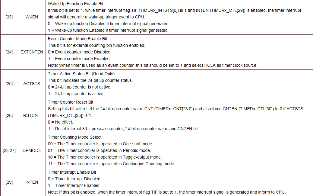
* |[23] |WKEN |Wake-Up Function Enable Bit
* | | |If this bit is set to 1, while timer interrupt flag TIF (TIMERx_INTSTS[0]) is 1 and INTEN (TIMERx_CTL[29]) is enabled, the timer interrupt signal will generate a wake-up trigger event to CPU.
* | | |0 = Wake-up function Disabled if timer interrupt signal generated.
* | | |1 = Wake-up function Enabled if timer interrupt signal generated.
* |[24] |EXTCNTEN |Event Counter Mode Enable Bit
* | | |This bit is for external counting pin function enabled.
* | | |0 = Event counter mode Disabled.
* | | |1 = Event counter mode Enabled.
* | | |Note: When timer is used as an event counter, this bit should be set to 1 and select HCLK as timer clock source.
* |[25] |ACTSTS |Timer Active Status Bit (Read Only)
* | | |This bit indicates the 24-bit up counter status.
* | | |0 = 24-bit up counter is not active.
* | | |1 = 24-bit up counter is active.
* |[26] |RSTCNT |Timer Counter Reset Bit
* | | |Setting this bit will reset the 24-bit up counter value CNT (TIMERx_CNT[23:0]) and also force CNTEN (TIMERx_CTL[30]) to 0 if ACTSTS (TIMERx_CTL[25]) is 1.
* | | |0 = No effect.
* | | |1 = Reset internal 8-bit prescale counter, 24-bit up counter value and CNTEN bit.
* |[28:27] |OPMODE |Timer Counting Mode Select
* | | |00 = The Timer controller is operated in One-shot mode.
* | | |01 = The Timer controller is operated in Periodic mode.
* | | |10 = The Timer controller is operated in Toggle-output mode.
* | | |11 = The Timer controller is operated in Continuous Counting mode.
* |[29] |INTEN |Timer Interrupt Enable Bit
* | | |0 = Timer Interrupt Disabled.
* | | |1 = Timer Interrupt Enabled.
* | | |Note: If this bit is enabled, when the timer interrupt flag TIF is set to 1, the timer interrupt signal is generated and inform to CPU.
* |[30] |CNTEN |Timer Counting Enable Bit
* | | |0 = Stops/Suspends counting.
* | | |1 = Starts counting.
* | | |Note1: In stop status, and then set CNTEN to 1 will enable the 24-bit up counter to keep counting from the last stop counting value.
* | | |Note2: This bit is auto-cleared by hardware in one-shot mode (TIMER_CTL[28:27] = 00) when the timer interrupt flag TIF (TIMERx_INTSTS[0]) is generated.
* |[31] |ICEDEBUG |ICE Debug Mode Acknowledge Disable
* | | |0 = ICE debug mode acknowledgement effects TIMER counting.
* | | |TIMER counter will be held while CPU is held by ICE.
* | | |1 = ICE debug mode acknowledgement Disabled.
* | | |TIMER counter will keep going no matter CPU is held by ICE or not.
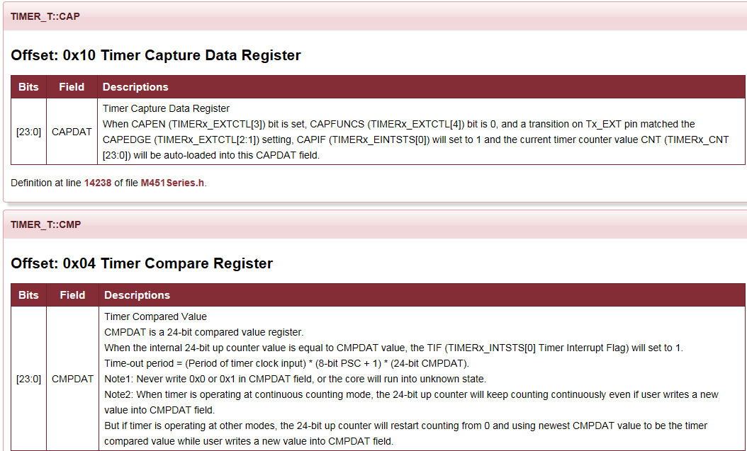
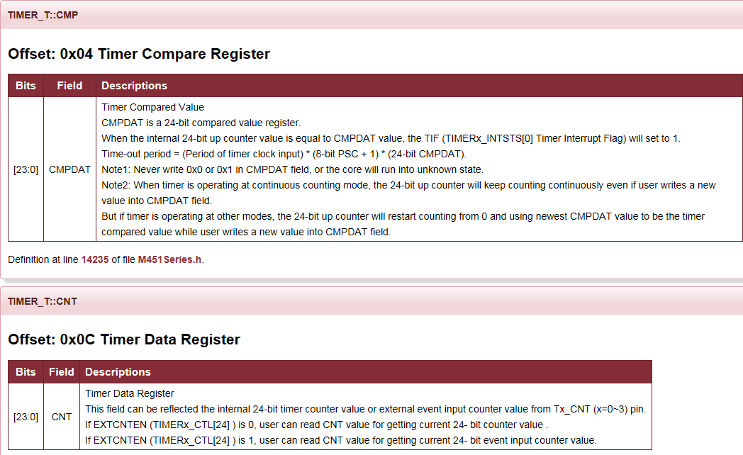
* @var TIMER_T::CMP
* Offset: 0x04 Timer Compare Register
* ---------------------------------------------------------------------------------------------------
* |Bits |Field |Descriptions
* | :----: | :----: | :---- |
* |[23:0] |CMPDAT |Timer Compared Value
* | | |CMPDAT is a 24-bit compared value register.
* | | |When the internal 24-bit up counter value is equal to CMPDAT value, the TIF (TIMERx_INTSTS[0] Timer Interrupt Flag) will set to 1.
* | | |Time-out period = (Period of timer clock input) * (8-bit PSC + 1) * (24-bit CMPDAT).
* | | |Note1: Never write 0x0 or 0x1 in CMPDAT field, or the core will run into unknown state.
* | | |Note2: When timer is operating at continuous counting mode, the 24-bit up counter will keep counting continuously even if user writes a new value into CMPDAT field.
* | | |But if timer is operating at other modes, the 24-bit up counter will restart counting from 0 and using newest CMPDAT value to be the timer compared value while user writes a new value into CMPDAT field.
* @var TIMER_T::INTSTS
* Offset: 0x08 Timer Interrupt Status Register
* ---------------------------------------------------------------------------------------------------
* |Bits |Field |Descriptions
* | :----: | :----: | :---- |
* |[0] |TIF |Timer Interrupt Flag
* | | |This bit indicates the interrupt flag status of Timer while 24-bit timer up counter CNT (TIMERx_CNT[23:0]) value reaches to CMPDAT (TIMERx_CMP[23:0]) value.
* | | |0 = No effect.
* | | |1 = CNT value matches the CMPDAT value.
* | | |Note: This bit is cleared by writing 1 to it.
* |[1] |TWKF |Timer Wake-Up Flag
* | | |This bit indicates the interrupt wake-up flag status of timer.
* | | |0 = Timer does not cause CPU wake-up.
* | | |1 = CPU wake-up from Idle or Power-down mode if timer time-out interrupt signal generated.
* | | |Note: This bit is cleared by writing 1 to it.
* @var TIMER_T::CNT
* Offset: 0x0C Timer Data Register
* ---------------------------------------------------------------------------------------------------
* |Bits |Field |Descriptions
* | :----: | :----: | :---- |
* |[23:0] |CNT |Timer Data Register
* | | |This field can be reflected the internal 24-bit timer counter value or external event input counter value from Tx_CNT (x=0~3) pin.
* | | |If EXTCNTEN (TIMERx_CTL[24] ) is 0, user can read CNT value for getting current 24- bit counter value .
* | | |If EXTCNTEN (TIMERx_CTL[24] ) is 1, user can read CNT value for getting current 24- bit event input counter value.
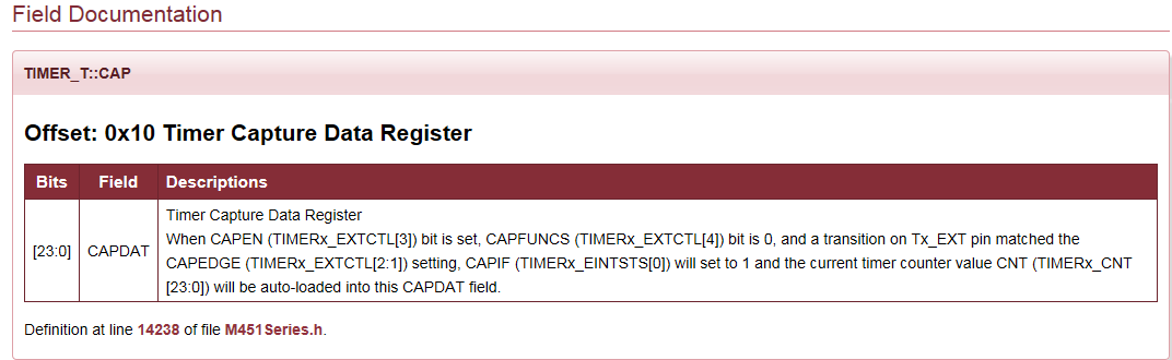
* @var TIMER_T::CAP
* Offset: 0x10 Timer Capture Data Register
* ---------------------------------------------------------------------------------------------------
* |Bits |Field |Descriptions
* | :----: | :----: | :---- |
* |[23:0] |CAPDAT |Timer Capture Data Register
* | | |When CAPEN (TIMERx_EXTCTL[3]) bit is set, CAPFUNCS (TIMERx_EXTCTL[4]) bit is 0, and a transition on Tx_EXT pin matched the CAPEDGE (TIMERx_EXTCTL[2:1]) setting, CAPIF (TIMERx_EINTSTS[0]) will set to 1 and the current timer counter value CNT (TIMERx_CNT[23:0]) will be auto-loaded into this CAPDAT field.
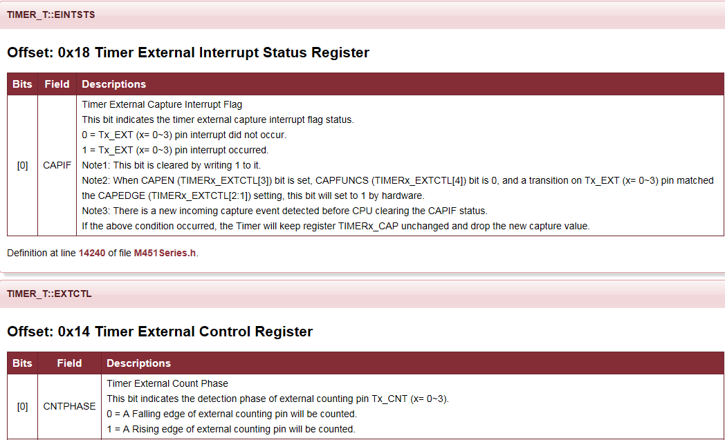
* @var TIMER_T::EXTCTL
* Offset: 0x14 Timer External Control Register
* ---------------------------------------------------------------------------------------------------
* |Bits |Field |Descriptions
* | :----: | :----: | :---- |
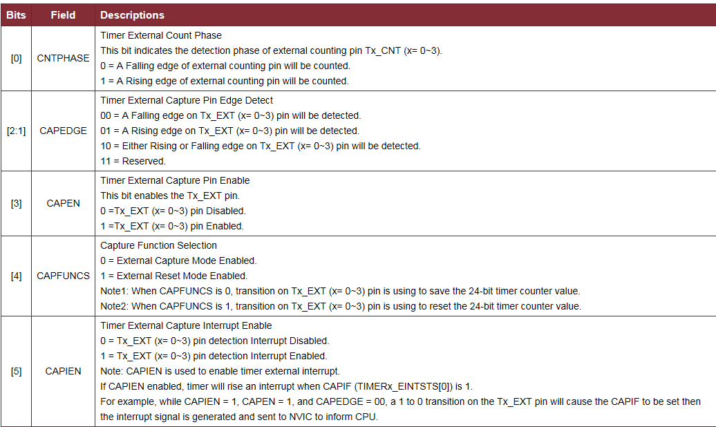
* |[0] |CNTPHASE |Timer External Count Phase
* | | |This bit indicates the detection phase of external counting pin Tx_CNT (x= 0~3).
* | | |0 = A Falling edge of external counting pin will be counted.
* | | |1 = A Rising edge of external counting pin will be counted.
* |[2:1] |CAPEDGE |Timer External Capture Pin Edge Detect
* | | |00 = A Falling edge on Tx_EXT (x= 0~3) pin will be detected.
* | | |01 = A Rising edge on Tx_EXT (x= 0~3) pin will be detected.
* | | |10 = Either Rising or Falling edge on Tx_EXT (x= 0~3) pin will be detected.
* | | |11 = Reserved.
* |[3] |CAPEN |Timer External Capture Pin Enable
* | | |This bit enables the Tx_EXT pin.
* | | |0 =Tx_EXT (x= 0~3) pin Disabled.
* | | |1 =Tx_EXT (x= 0~3) pin Enabled.
* |[4] |CAPFUNCS |Capture Function Selection
* | | |0 = External Capture Mode Enabled.
* | | |1 = External Reset Mode Enabled.
* | | |Note1: When CAPFUNCS is 0, transition on Tx_EXT (x= 0~3) pin is using to save the 24-bit timer counter value.
* | | |Note2: When CAPFUNCS is 1, transition on Tx_EXT (x= 0~3) pin is using to reset the 24-bit timer counter value.
* |[5] |CAPIEN |Timer External Capture Interrupt Enable
* | | |0 = Tx_EXT (x= 0~3) pin detection Interrupt Disabled.
* | | |1 = Tx_EXT (x= 0~3) pin detection Interrupt Enabled.
* | | |Note: CAPIEN is used to enable timer external interrupt.
* | | |If CAPIEN enabled, timer will rise an interrupt when CAPIF (TIMERx_EINTSTS[0]) is 1.
* | | |For example, while CAPIEN = 1, CAPEN = 1, and CAPEDGE = 00, a 1 to 0 transition on the Tx_EXT pin will cause the CAPIF to be set then the interrupt signal is generated and sent to NVIC to inform CPU.
* |[6] |CAPDBEN |Timer External Capture Pin De-Bounce Enable
* | | |0 = Tx_EXT (x= 0~3) pin de-bounce Disabled.
* | | |1 = Tx_EXT (x= 0~3) pin de-bounce Enabled.
* | | |Note: If this bit is enabled, the edge detection of Tx_EXT pin is detected with de-bounce circuit.
* |[7] |CNTDBEN |Timer Counter Pin De-Bounce Enable
* | | |0 = Tx_CNT (x= 0~3) pin de-bounce Disabled.
* | | |1 = Tx_CNT (x= 0~3) pin de-bounce Enabled.
* | | |Note: If this bit is enabled, the edge detection of Tx_CNT pin is detected with de-bounce circuit.
* @var TIMER_T::EINTSTS
* Offset: 0x18 Timer External Interrupt Status Register
* ---------------------------------------------------------------------------------------------------
* |Bits |Field |Descriptions
* | :----: | :----: | :---- |
* |[0] |CAPIF |Timer External Capture Interrupt Flag
* | | |This bit indicates the timer external capture interrupt flag status.
* | | |0 = Tx_EXT (x= 0~3) pin interrupt did not occur.
* | | |1 = Tx_EXT (x= 0~3) pin interrupt occurred.
* | | |Note1: This bit is cleared by writing 1 to it.
* | | |Note2: When CAPEN (TIMERx_EXTCTL[3]) bit is set, CAPFUNCS (TIMERx_EXTCTL[4]) bit is 0, and a transition on Tx_EXT (x= 0~3) pin matched the CAPEDGE (TIMERx_EXTCTL[2:1]) setting, this bit will set to 1 by hardware.
* | | |Note3: There is a new incoming capture event detected before CPU clearing the CAPIF status.
* | | |If the above condition occurred, the Timer will keep register TIMERx_CAP unchanged and drop the new capture value.
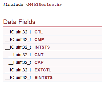
*/ __IO uint32_t CTL; /* Offset: 0x00 Timer Control and Status Register */
__IO uint32_t CMP; /* Offset: 0x04 Timer Compare Register */
__IO uint32_t INTSTS; /* Offset: 0x08 Timer Interrupt Status Register */
__I uint32_t CNT; /* Offset: 0x0C Timer Data Register */
__I uint32_t CAP; /* Offset: 0x10 Timer Capture Data Register */
__IO uint32_t EXTCTL; /* Offset: 0x14 Timer External Control Register */
__IO uint32_t EINTSTS; /* Offset: 0x18 Timer External Interrupt Status Register */ } TIMER_T; /**
@addtogroup TMR_CONST TMR Bit Field Definition
Constant Definitions for TMR Controller
@{ */ #define TIMER_CTL_PSC_Pos (0) /*!< TIMER_T::CTL: PSC Position */
#define TIMER_CTL_PSC_Msk (0xfful << TIMER_CTL_PSC_Pos) /*!< TIMER_T::CTL: PSC Mask */ #define TIMER_CTL_WKTKEN_Pos (17) /*!< TIMER_T::CTL: WKTKEN Position */
#define TIMER_CTL_WKTKEN_Msk (0x1ul << TIMER_CTL_WKTKEN_Pos) /*!< TIMER_T::CTL: WKTKEN Mask */ #define TIMER_CTL_TRGSSEL_Pos (18) /*!< TIMER_T::CTL: TRGSSEL Position */
#define TIMER_CTL_TRGSSEL_Msk (0x1ul << TIMER_CTL_TRGSSEL_Pos) /*!< TIMER_T::CTL: TRGSSEL Mask */ #define TIMER_CTL_TRGPWM_Pos (19) /*!< TIMER_T::CTL: TRGPWM Position */
#define TIMER_CTL_TRGPWM_Msk (0x1ul << TIMER_CTL_TRGPWM_Pos) /*!< TIMER_T::CTL: TRGPWM Mask */ #define TIMER_CTL_TRGDAC_Pos (20) /*!< TIMER_T::CTL: TRGDAC Position */
#define TIMER_CTL_TRGDAC_Msk (0x1ul << TIMER_CTL_TRGDAC_Pos) /*!< TIMER_T::CTL: TRGDAC Mask */ #define TIMER_CTL_TRGEADC_Pos (21) /*!< TIMER_T::CTL: TRGEADC Position */
#define TIMER_CTL_TRGEADC_Msk (0x1ul << TIMER_CTL_TRGEADC_Pos) /*!< TIMER_T::CTL: TRGEADC Mask */ #define TIMER_CTL_TGLPINSEL_Pos (22) /*!< TIMER_T::CTL: TGLPINSEL Position */
#define TIMER_CTL_TGLPINSEL_Msk (0x1ul << TIMER_CTL_TGLPINSEL_Pos) /*!< TIMER_T::CTL: TGLPINSEL Mask */ #define TIMER_CTL_WKEN_Pos (23) /*!< TIMER_T::CTL: WKEN Position */
#define TIMER_CTL_WKEN_Msk (0x1ul << TIMER_CTL_WKEN_Pos) /*!< TIMER_T::CTL: WKEN Mask */ #define TIMER_CTL_EXTCNTEN_Pos (24) /*!< TIMER_T::CTL: EXTCNTEN Position */
#define TIMER_CTL_EXTCNTEN_Msk (0x1ul << TIMER_CTL_EXTCNTEN_Pos) /*!< TIMER_T::CTL: EXTCNTEN Mask */ #define TIMER_CTL_ACTSTS_Pos (25) /*!< TIMER_T::CTL: ACTSTS Position */
#define TIMER_CTL_ACTSTS_Msk (0x1ul << TIMER_CTL_ACTSTS_Pos) /*!< TIMER_T::CTL: ACTSTS Mask */ #define TIMER_CTL_RSTCNT_Pos (26) /*!< TIMER_T::CTL: RSTCNT Position */
#define TIMER_CTL_RSTCNT_Msk (0x1ul << TIMER_CTL_RSTCNT_Pos) /*!< TIMER_T::CTL: RSTCNT Mask */ #define TIMER_CTL_OPMODE_Pos (27) /*!< TIMER_T::CTL: OPMODE Position */
#define TIMER_CTL_OPMODE_Msk (0x3ul << TIMER_CTL_OPMODE_Pos) /*!< TIMER_T::CTL: OPMODE Mask */ #define TIMER_CTL_INTEN_Pos (29) /*!< TIMER_T::CTL: INTEN Position */
#define TIMER_CTL_INTEN_Msk (0x1ul << TIMER_CTL_INTEN_Pos) /*!< TIMER_T::CTL: INTEN Mask */ #define TIMER_CTL_CNTEN_Pos (30) /*!< TIMER_T::CTL: CNTEN Position */
#define TIMER_CTL_CNTEN_Msk (0x1ul << TIMER_CTL_CNTEN_Pos) /*!< TIMER_T::CTL: CNTEN Mask */ #define TIMER_CTL_ICEDEBUG_Pos (31) /*!< TIMER_T::CTL: ICEDEBUG Position */
#define TIMER_CTL_ICEDEBUG_Msk (0x1ul << TIMER_CTL_ICEDEBUG_Pos) /*!< TIMER_T::CTL: ICEDEBUG Mask */ #define TIMER_CMP_CMPDAT_Pos (0) /*!< TIMER_T::CMP: CMPDAT Position */
#define TIMER_CMP_CMPDAT_Msk (0xfffffful << TIMER_CMP_CMPDAT_Pos) /*!< TIMER_T::CMP: CMPDAT Mask */ #define TIMER_INTSTS_TIF_Pos (0) /*!< TIMER_T::INTSTS: TIF Position */
#define TIMER_INTSTS_TIF_Msk (0x1ul << TIMER_INTSTS_TIF_Pos) /*!< TIMER_T::INTSTS: TIF Mask */ #define TIMER_INTSTS_TWKF_Pos (1) /*!< TIMER_T::INTSTS: TWKF Position */
#define TIMER_INTSTS_TWKF_Msk (0x1ul << TIMER_INTSTS_TWKF_Pos) /*!< TIMER_T::INTSTS: TWKF Mask */ #define TIMER_CNT_CNT_Pos (0) /*!< TIMER_T::CNT: CNT Position */
#define TIMER_CNT_CNT_Msk (0xfffffful << TIMER_CNT_CNT_Pos) /*!< TIMER_T::CNT: CNT Mask */ #define TIMER_CAP_CAPDAT_Pos (0) /*!< TIMER_T::CAP: CAPDAT Position */
#define TIMER_CAP_CAPDAT_Msk (0xfffffful << TIMER_CAP_CAPDAT_Pos) /*!< TIMER_T::CAP: CAPDAT Mask */ #define TIMER_EXTCTL_CNTPHASE_Pos (0) /*!< TIMER_T::EXTCTL: CNTPHASE Position */
#define TIMER_EXTCTL_CNTPHASE_Msk (0x1ul << TIMER_EXTCTL_CNTPHASE_Pos) /*!< TIMER_T::EXTCTL: CNTPHASE Mask */ #define TIMER_EXTCTL_CAPEDGE_Pos (1) /*!< TIMER_T::EXTCTL: CAPEDGE Position */
#define TIMER_EXTCTL_CAPEDGE_Msk (0x3ul << TIMER_EXTCTL_CAPEDGE_Pos) /*!< TIMER_T::EXTCTL: CAPEDGE Mask */ #define TIMER_EXTCTL_CAPEN_Pos (3) /*!< TIMER_T::EXTCTL: CAPEN Position */
#define TIMER_EXTCTL_CAPEN_Msk (0x1ul << TIMER_EXTCTL_CAPEN_Pos) /*!< TIMER_T::EXTCTL: CAPEN Mask */ #define TIMER_EXTCTL_CAPFUNCS_Pos (4) /*!< TIMER_T::EXTCTL: CAPFUNCS Position */
#define TIMER_EXTCTL_CAPFUNCS_Msk (0x1ul << TIMER_EXTCTL_CAPFUNCS_Pos) /*!< TIMER_T::EXTCTL: CAPFUNCS Mask */ #define TIMER_EXTCTL_CAPIEN_Pos (5) /*!< TIMER_T::EXTCTL: CAPIEN Position */
#define TIMER_EXTCTL_CAPIEN_Msk (0x1ul << TIMER_EXTCTL_CAPIEN_Pos) /*!< TIMER_T::EXTCTL: CAPIEN Mask */ #define TIMER_EXTCTL_CAPDBEN_Pos (6) /*!< TIMER_T::EXTCTL: CAPDBEN Position */
#define TIMER_EXTCTL_CAPDBEN_Msk (0x1ul << TIMER_EXTCTL_CAPDBEN_Pos) /*!< TIMER_T::EXTCTL: CAPDBEN Mask */ #define TIMER_EXTCTL_CNTDBEN_Pos (7) /*!< TIMER_T::EXTCTL: CNTDBEN Position */
#define TIMER_EXTCTL_CNTDBEN_Msk (0x1ul << TIMER_EXTCTL_CNTDBEN_Pos) /*!< TIMER_T::EXTCTL: CNTDBEN Mask */ #define TIMER_EINTSTS_CAPIF_Pos (0) /*!< TIMER_T::EINTSTS: CAPIF Position */
#define TIMER_EINTSTS_CAPIF_Msk (0x1ul << TIMER_EINTSTS_CAPIF_Pos) /*!< TIMER_T::EINTSTS: CAPIF Mask */ /**@}*/ /* TIMER_CONST */
/**@}*/ /* end of TIMER register group */
#define TIMER0               ((TIMER_T *) TMR01_BASE)

#define TIMER1               ((TIMER_T *) (TMR01_BASE + 0x20))

#define TIMER2               ((TIMER_T *) TMR23_BASE)

#define TIMER3               ((TIMER_T *) (TMR23_BASE+ 0x20))
/** @addtogroup TIMER_EXPORTED_CONSTANTS TIMER Exported Constants

  @{

*/

/*---------------------------------------------------------------------------------------------------------*/

/*  TIMER Operation Mode, External Counter and Capture Mode Constant Definitions                           */

/*---------------------------------------------------------------------------------------------------------*/

#define TIMER_ONESHOT_MODE                      (0UL << TIMER_CTL_OPMODE_Pos)      /*!< Timer working in one-shot mode */

#define TIMER_PERIODIC_MODE                     (1UL << TIMER_CTL_OPMODE_Pos)      /*!< Timer working in periodic mode */

#define TIMER_TOGGLE_MODE                       (2UL << TIMER_CTL_OPMODE_Pos)      /*!< Timer working in toggle-output mode */

#define TIMER_CONTINUOUS_MODE                   (3UL << TIMER_CTL_OPMODE_Pos)      /*!< Timer working in continuous counting mode */

#define TIMER_TOUT_PIN_FROM_TX                  (0UL << TIMER_CTL_TGLPINSEL_Pos)   /*!< Timer toggle-output pin is from Tx pin */

#define TIMER_TOUT_PIN_FROM_TX_EXT              (1UL << TIMER_CTL_TGLPINSEL_Pos)   /*!< Timer toggle-output pin is from Tx_EXT pin */

#define TIMER_CAPTURE_FREE_COUNTING_MODE        (0UL << TIMER_EXTCTL_CAPFUNCS_Pos) /*!< Timer capture event to get timer counter value */

#define TIMER_CAPTURE_COUNTER_RESET_MODE        (1UL << TIMER_EXTCTL_CAPFUNCS_Pos) /*!< Timer capture event to reset timer counter */

#define TIMER_CAPTURE_FALLING_EDGE              (0UL << TIMER_EXTCTL_CAPEDGE_Pos)  /*!< Falling edge detection to trigger timer capture */

#define TIMER_CAPTURE_RISING_EDGE               (1UL << TIMER_EXTCTL_CAPEDGE_Pos)  /*!< Rising edge detection to trigger timer capture */

#define TIMER_CAPTURE_FALLING_AND_RISING_EDGE   (2UL << TIMER_EXTCTL_CAPEDGE_Pos)  /*!< Both falling and rising edge detection to trigger timer capture */

#define TIMER_COUNTER_FALLING_EDGE              (0UL << TIMER_EXTCTL_CNTPHASE_Pos) /*!< Counter increase on falling edge detection */

#define TIMER_COUNTER_RISING_EDGE               (1UL << TIMER_EXTCTL_CNTPHASE_Pos) /*!< Counter increase on rising edge detection */

/*@}*/ /* end of group TIMER_EXPORTED_CONSTANTS */
TIMER1->CMP = ((SystemCoreClock / 4) / 2);

    TIMER1->CTL = TIMER_CTL_INTEN_Msk | TIMER_PERIODIC_MODE;

    TIMER_SET_PRESCALE_VALUE(TIMER1, 3);
One–shot模式
如果定时器工作在单周期 (one-shot) 模式(TIMERx_CTL[28:27]为00,且CNTEN (TIMERx_CTL[30])置1),则定时器的计数器开始计数。一旦CNT (TIMERx_CNT[23:0])计数器的值达到CMPDAT (TIMERx_CMP[23:0])的值时,TIF (TIMERx_INTSTS[0])标志将变为1,CNT的值和 CNTEN位将由定时器控制器自动清零,然后定时器计数操作停止。与此同时,如果INTEN (TIMERx_CTL[29])位使能,则定时器中断信号产生并送到 NVIC通知CPU。(参见数据手册上的数据)
#define TIMER_CTL_OPMODE_Pos               (27)                                            /*!< TIMER_T::CTL: OPMODE Position               */

#define TIMER_CTL_OPMODE_Msk               (0x3ul << TIMER_CTL_OPMODE_Pos)                 /*!< TIMER_T::CTL: OPMODE Mask
如果定时器工作在周期 (periodic) 模式(TIMERx_CTL[28:27]为01)且CNTEN (TIMERx_CTL[30])置1,则定时器的计数器开始向上计数。一旦CNT (TIMERx_CNT[23:0])计数器的值达到CMPDAT (TIMERx_CMP[23:0])的值时,TIF (TIMERx_INTSTS[0])标志将变为1,CNT的值将由定时器控制器自动清零,然后定时器重新计数。与此同时,如果INTEN (TIMERx_CTL[29])使能,则定时器中断信号产生并送到 NVIC 通知 CPU 。在该模式,定时器控制器周期性地操作计数和 与CMPDAT的值比较,直到CNTEN位由软件清0。
M451定时器的寄存器讲解的更多相关文章
- 说说M451例程之PWM的寄存器讲解
M451提供了两路PWM发生器.每路PWM支持6通道PWM输出或输入捕捉.有一个12位的预分频器把时钟源分频后输入给16位的计数器,另外还有一个16位的比较器.PWM计数器支持向上,向下,上下计数方式 ...
- STM32 通用定时器相关寄存器
TIMx_CR1(控制寄存器1) 9-8位:CKD[1:0]时钟分频因子,定义在定时器时钟(CK_INT)频率与数字滤波器(ETR,TIx)使用的采样频率之间的分频比例. 定义:00(tDTS = t ...
- JZ2440 裸机驱动 第10章 系统时钟和定时器
本章目标 了解S3C2410/S3C2440的时钟体系结构 掌握通过设置MPLL改变系统时钟的方法 掌握在不同的频率下设置存储控制器的方法 掌握PWM定时器的用法 ...
- 第32章 TIM—高级定时器—零死角玩转STM32-F429系列
第32章 TIM—高级定时器 全套200集视频教程和1000页PDF教程请到秉火论坛下载:www.firebbs.cn 野火视频教程优酷观看网址:http://i.youku.com/fire ...
- 【STM32H7教程】第22章 STM32H7的SysTick实现多组软件定时器
完整教程下载地址:http://forum.armfly.com/forum.php?mod=viewthread&tid=86980 第22章 STM32H7的SysTick实现 ...
- 【STM32H7教程】第32章 STM32H7的TIM定时器基础知识和HAL库API
完整教程下载地址:http://www.armbbs.cn/forum.php?mod=viewthread&tid=86980 第32章 STM32H7的TIM定时器基础知识和H ...
- 定时器及PWM
1 定时器 1.1 定时器分类 对于STM32来说,定时器可分为基本定时器.通用定时器.高级定时器三类,后者包括前者的全部功能.以stm32f1系列为例,TIM6和TIM7为基本定时器,TIM2~TI ...
- [Zigbee]定时器1
注意:在定时器可以使用一个输入/输出引脚之前,所需的 I/O 引脚必须配置为定时器 1 的外设引脚. 定时器1的引脚映射方案选用是备用2方案:P07对应通道3.P06-通道4.P12-通道0.P11- ...
- STM32之定时器
一.定时器简介 1.时钟来源 2.定时器结构(以基本定时器为例) 二.基本定时器的编程方法 1.基本定时器的寄存器 2.例程 /** * @brief 定时器6的初始化,定时周期0.01s * @pa ...
随机推荐
- Solr 4.0部署
http://www.blogjava.net/xiaohuzi2008/archive/2012/12/03/392373.html
- PHP代码优化之缓存(转)
我们在编写程序时,总是想要使自己的程序占用资源最小,运行速度更快,代码量更少.往往我们在追求这些的同时却失去了很多东西.下面我想讲讲我对PHP优化的理解.优化的目的是花最少的代价换来最快的运行速度与最 ...
- Redis全方位讲解--哨兵模式(Sentinel模式)(转载)
前言 当按照上一篇<redis主从复制>部署好之后,我们会想,一旦redis的master出现了宕机,并且我们并没有及时发现,这时候就可能会出现数据丢失或程序无法运行.此时,redis的哨 ...
- Android的xml/assets/raw资源使用具体解释
一.assets/xml/raw资源介绍 1.assets资源文件夹:assets文件夹下存放的资源代表应用无法直接訪问的原生资源,这些文件将原封不动的存储到设备上,不会被编译为二进制形式,訪问方式是 ...
- python None 和 NaN
python原生的None和pandas, numpy中的numpy.NaN尽管在功能上都是用来标示空缺数据.但它们的行为在很多场景下确有一些相当大的差异.由于不熟悉这些差异,曾经给我的工作带来过不少 ...
- AutoFac文档12(转载)
目录 开始 Registering components 控制范围和生命周期 用模块结构化Autofac xml配置 与.net集成 深入理解Autofac 指导 关于 词汇表 Resolve的参数 ...
- ecshop报错”Deprecated: Assigning the return value of…”解决办法
ECSHOP生成站点地图提示”Deprecated: Assigning the return value of new by reference is deprecated in…”. 我的问题在批 ...
- FTPHelper-封装FTP的相关操作
using System; using System.IO; using System.Net; using System.Text; namespace Whir.Software.DataSync ...
- ruby配置相关
1.安装ruby 方式1: yum install ruby 方式2:https://www.ruby-lang.org/en/downloads/ 使用源码安装 ./configure make m ...
- 【Android】13.4 使用SQLite.NET.Async-PCL访问SQLite数据库
分类:C#.Android.VS2015: 创建日期:2016-02-27 一.简介 这一节演示如何利用以异步方式(async.await)访问SQLite数据库. 二.示例4运行截图 下面左图为初始 ...