STM32F4 DMA2D_M2M_PFC
此例程为STM324x9I_EVAL:DCMI_CaptureMode,使用的stm32f4xx_hal_driver,
At each camera line event, the line is converted to ARGB8888 pixel format
and transferred to LCD_FRAME_BUFFER using DMA2D.
这里仅记录例程中DMA2D这段,Camera RGB565格式 LCD RGB888
 /**

   * @brief  Converts a line to an ARGB8888 pixel format.

   * @param  pSrc: Pointer to source buffer

   * @param  pDst: Output color

   * @param  xSize: Buffer width

   * @param  ColorMode: Input color mode

   * @retval None

   */

 static void LCD_LL_ConvertLineToARGB8888(void *pSrc, void *pDst)

 {

   /* Enable DMA2D clock */

   __HAL_RCC_DMA2D_CLK_ENABLE();

   /* Configure the DMA2D Mode, Color Mode and output offset */

   hdma2d_eval.Init.Mode         = DMA2D_M2M_PFC;

   hdma2d_eval.Init.ColorMode    = DMA2D_ARGB8888;

   hdma2d_eval.Init.OutputOffset = ;

   /* Foreground Configuration */

   hdma2d_eval.LayerCfg[].AlphaMode = DMA2D_NO_MODIF_ALPHA;

   hdma2d_eval.LayerCfg[].InputAlpha = 0xFF;

   hdma2d_eval.LayerCfg[].InputColorMode = CM_RGB565;

   hdma2d_eval.LayerCfg[].InputOffset = ;

   hdma2d_eval.Instance = DMA2D;

   /* DMA2D Initialization */

   if(HAL_DMA2D_Init(&hdma2d_eval) == HAL_OK)

   {

     if(HAL_DMA2D_ConfigLayer(&hdma2d_eval, ) == HAL_OK)

     {

       if (HAL_DMA2D_Start(&hdma2d_eval, (uint32_t)pSrc, (uint32_t)pDst, BSP_LCD_GetXSize(), ) == HAL_OK)

       {

         /* Polling For DMA transfer */

         HAL_DMA2D_PollForTransfer(&hdma2d_eval, );

       }

     }

   }

   else

   {

     /* FatFs Initialization Error */

     Error_Handler();

   }

 }
LCD_LL_ConvertLineToARGB8888
分析初始化中代码:static DMA2D_HandleTypeDef hdma2d_eval;
 typedef struct __DMA2D_HandleTypeDef

 {

   DMA2D_TypeDef               *Instance;                                                    /*!< DMA2D Register base address       */

   DMA2D_InitTypeDef           Init;                                                         /*!< DMA2D communication parameters    */

   void                        (* XferCpltCallback)(struct __DMA2D_HandleTypeDef * hdma2d);  /*!< DMA2D transfer complete callback  */

   void                        (* XferErrorCallback)(struct __DMA2D_HandleTypeDef * hdma2d); /*!< DMA2D transfer error callback     */

   DMA2D_LayerCfgTypeDef       LayerCfg[MAX_DMA2D_LAYER];                                    /*!< DMA2D Layers parameters           */

   HAL_LockTypeDef             Lock;                                                         /*!< DMA2D Lock                        */

   __IO HAL_DMA2D_StateTypeDef State;                                                        /*!< DMA2D transfer state              */

   __IO uint32_t               ErrorCode;                                                    /*!< DMA2D Error code                  */

 } DMA2D_HandleTypeDef;
DMA2D_HandleTypeDef
typedef struct
{
__IO uint32_t CR; /*!< DMA2D Control Register, Address offset: 0x00 */
__IO uint32_t ISR; /*!< DMA2D Interrupt Status Register, Address offset: 0x04 */
__IO uint32_t IFCR; /*!< DMA2D Interrupt Flag Clear Register, Address offset: 0x08 */
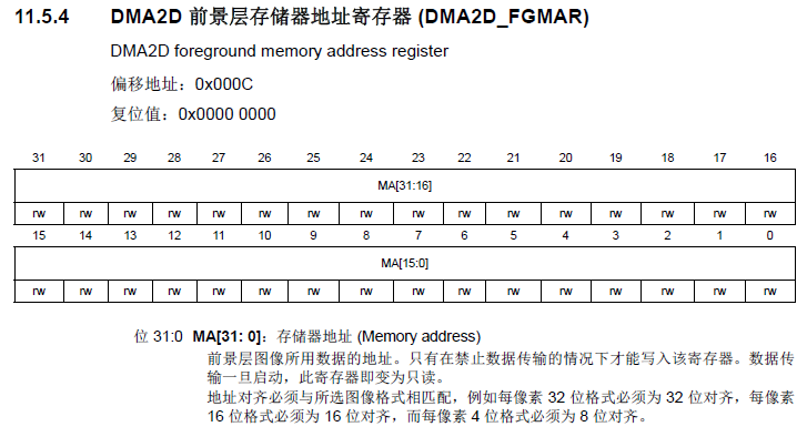
__IO uint32_t FGMAR; /*!< DMA2D Foreground Memory Address Register, Address offset: 0x0C */
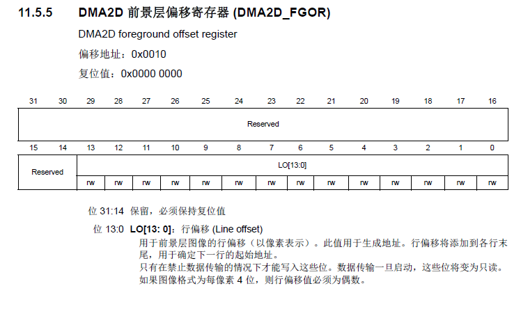
__IO uint32_t FGOR; /*!< DMA2D Foreground Offset Register, Address offset: 0x10 */
__IO uint32_t BGMAR; /*!< DMA2D Background Memory Address Register, Address offset: 0x14 */
__IO uint32_t BGOR; /*!< DMA2D Background Offset Register, Address offset: 0x18 */
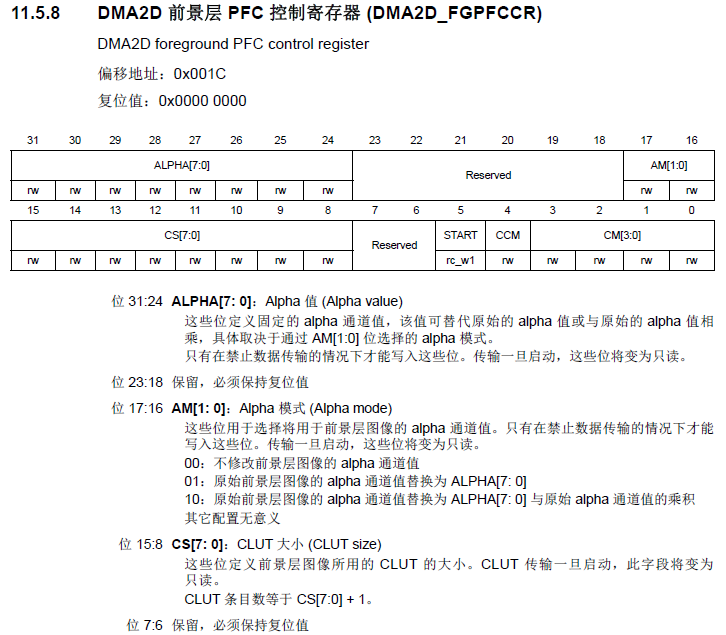
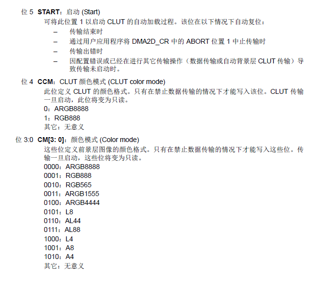
__IO uint32_t FGPFCCR; /*!< DMA2D Foreground PFC Control Register, Address offset: 0x1C */
__IO uint32_t FGCOLR; /*!< DMA2D Foreground Color Register, Address offset: 0x20 */
__IO uint32_t BGPFCCR; /*!< DMA2D Background PFC Control Register, Address offset: 0x24 */
__IO uint32_t BGCOLR; /*!< DMA2D Background Color Register, Address offset: 0x28 */
__IO uint32_t FGCMAR; /*!< DMA2D Foreground CLUT Memory Address Register, Address offset: 0x2C */
__IO uint32_t BGCMAR; /*!< DMA2D Background CLUT Memory Address Register, Address offset: 0x30 */
__IO uint32_t OPFCCR; /*!< DMA2D Output PFC Control Register, Address offset: 0x34 */
__IO uint32_t OCOLR; /*!< DMA2D Output Color Register, Address offset: 0x38 */
__IO uint32_t OMAR; /*!< DMA2D Output Memory Address Register, Address offset: 0x3C */
__IO uint32_t OOR; /*!< DMA2D Output Offset Register, Address offset: 0x40 */
__IO uint32_t NLR; /*!< DMA2D Number of Line Register, Address offset: 0x44 */
__IO uint32_t LWR; /*!< DMA2D Line Watermark Register, Address offset: 0x48 */
__IO uint32_t AMTCR; /*!< DMA2D AHB Master Timer Configuration Register, Address offset: 0x4C */
uint32_t RESERVED[]; /*!< Reserved, 0x50-0x3FF */
__IO uint32_t FGCLUT[]; /*!< DMA2D Foreground CLUT, Address offset:400-7FF */
__IO uint32_t BGCLUT[]; /*!< DMA2D Background CLUT, Address offset:800-BFF */
} DMA2D_TypeDef;
DMA2D_TypeDef
 /**

   * @brief DMA2D Init structure definition

   */

 typedef struct

 {

   uint32_t             Mode;               /*!< configures the DMA2D transfer mode.

                                                 This parameter can be one value of @ref DMA2D_Mode */

   uint32_t             ColorMode;          /*!< configures the color format of the output image.

                                                 This parameter can be one value of @ref DMA2D_Color_Mode */

   uint32_t             OutputOffset;       /*!< Specifies the Offset value.

                                                 This parameter must be a number between Min_Data = 0x0000 and Max_Data = 0x3FFF. */

 } DMA2D_InitTypeDef;
DMA2D_InitTypeDef
/* Configure the DMA2D Mode, Color Mode and output offset */
hdma2d_eval.Init.Mode = DMA2D_M2M_PFC; //DMA2D_CR DMA2D模式
hdma2d_eval.Init.ColorMode = DMA2D_ARGB8888; //DMA2D_OPFCCR 输出颜色模式
hdma2d_eval.Init.OutputOffset = 0; //DMA2D_OOR
这三个在上一篇中已经分析过这三个参数在HAL_DMA2D_Init(&hdma2d_eval)中执行
 /**

   * @brief  Initializes the DMA2D according to the specified

   *         parameters in the DMA2D_InitTypeDef and create the associated handle.

   * @param  hdma2d: pointer to a DMA2D_HandleTypeDef structure that contains

   *                 the configuration information for the DMA2D.

   * @retval HAL status

   */

 HAL_StatusTypeDef HAL_DMA2D_Init(DMA2D_HandleTypeDef *hdma2d)

 {

   uint32_t tmp = ;

   /* Check the DMA2D peripheral state */

   if(hdma2d == NULL)

   {

      return HAL_ERROR;

   }

   /* Check the parameters */

   assert_param(IS_DMA2D_ALL_INSTANCE(hdma2d->Instance));

   assert_param(IS_DMA2D_MODE(hdma2d->Init.Mode));

   assert_param(IS_DMA2D_CMODE(hdma2d->Init.ColorMode));

   assert_param(IS_DMA2D_OFFSET(hdma2d->Init.OutputOffset));

   if(hdma2d->State == HAL_DMA2D_STATE_RESET)

   {

     /* Allocate lock resource and initialize it */

     hdma2d->Lock = HAL_UNLOCKED;

     /* Init the low level hardware */

     HAL_DMA2D_MspInit(hdma2d);

   }

   /* Change DMA2D peripheral state */

   hdma2d->State = HAL_DMA2D_STATE_BUSY;

 /* DMA2D CR register configuration -------------------------------------------*/

   /* Get the CR register value */

   tmp = hdma2d->Instance->CR;

   /* Clear Mode bits */

   tmp &= (uint32_t)~DMA2D_CR_MODE;

   /* Prepare the value to be wrote to the CR register */

   tmp |= hdma2d->Init.Mode;

   /* Write to DMA2D CR register */

   hdma2d->Instance->CR = tmp;

 /* DMA2D OPFCCR register configuration ---------------------------------------*/

   /* Get the OPFCCR register value */

   tmp = hdma2d->Instance->OPFCCR;

   /* Clear Color Mode bits */

   tmp &= (uint32_t)~DMA2D_OPFCCR_CM;

   /* Prepare the value to be wrote to the OPFCCR register */

   tmp |= hdma2d->Init.ColorMode;

   /* Write to DMA2D OPFCCR register */

   hdma2d->Instance->OPFCCR = tmp;

 /* DMA2D OOR register configuration ------------------------------------------*/

   /* Get the OOR register value */

   tmp = hdma2d->Instance->OOR;

   /* Clear Offset bits */

   tmp &= (uint32_t)~DMA2D_OOR_LO;

   /* Prepare the value to be wrote to the OOR register */

   tmp |= hdma2d->Init.OutputOffset;

   /* Write to DMA2D OOR register */

   hdma2d->Instance->OOR = tmp;

   /* Update error code */

   hdma2d->ErrorCode = HAL_DMA2D_ERROR_NONE;

   /* Initialize the DMA2D state*/

   hdma2d->State  = HAL_DMA2D_STATE_READY;

   return HAL_OK;

 }
HAL_DMA2D_Init
hdma2d_eval.Instance = DMA2D;
DMA2D_TypeDef *Instance;
#define DMA2D ((DMA2D_TypeDef *)DMA2D_BASE)
这里是指向DMA2D的寄存器
 /**

   * @brief DMA2D Layer structure definition

   */

 typedef struct

 {

   uint32_t             InputOffset;       /*!< configures the DMA2D foreground offset.

                                                This parameter must be a number between Min_Data = 0x0000 and Max_Data = 0x3FFF. */

   uint32_t             InputColorMode;    /*!< configures the DMA2D foreground color mode .

                                                This parameter can be one value of @ref DMA2D_Input_Color_Mode */

   uint32_t             AlphaMode;         /*!< configures the DMA2D foreground alpha mode.

                                                This parameter can be one value of @ref DMA2D_ALPHA_MODE */

   uint32_t             InputAlpha;        /*!< Specifies the DMA2D foreground alpha value and color value in case of A8 or A4 color mode.

                                                This parameter must be a number between Min_Data = 0x00000000 and Max_Data = 0xFFFFFFFF

                                                in case of A8 or A4 color mode (ARGB).

                                                Otherwise, This parameter must be a number between Min_Data = 0x00 and Max_Data = 0xFF.*/

 } DMA2D_LayerCfgTypeDef;
DMA2D_LayerCfgTypeDef
/* Foreground Configuration */
hdma2d_eval.LayerCfg[1].AlphaMode = DMA2D_NO_MODIF_ALPHA; //DMA2D_FGPFCCR
hdma2d_eval.LayerCfg[1].InputAlpha = 0xFF; //DMA2D_FGPFCCR
hdma2d_eval.LayerCfg[1].InputColorMode = CM_RGB565; //DMA2D_FGPFCCR
hdma2d_eval.LayerCfg[1].InputOffset = 0; //DMA2D_FGOR
前景色的配置,由摄像头输入,配置了透明度和颜色模式与偏移
设置函数:HAL_DMA2D_ConfigLayer(&hdma2d_eval, 1)
 /**

   * @brief  Configure the DMA2D Layer according to the specified

   *         parameters in the DMA2D_InitTypeDef and create the associated handle.

   * @param  hdma2d: pointer to a DMA2D_HandleTypeDef structure that contains

   *                 the configuration information for the DMA2D.

   * @param  LayerIdx: DMA2D Layer index.

   *                   This parameter can be one of the following values:

   *                   0(background) / 1(foreground)

   * @retval HAL status

   */

 HAL_StatusTypeDef HAL_DMA2D_ConfigLayer(DMA2D_HandleTypeDef *hdma2d, uint32_t LayerIdx)

 {

   DMA2D_LayerCfgTypeDef *pLayerCfg = &hdma2d->LayerCfg[LayerIdx];

   uint32_t tmp = ;

   /* Process locked */

   __HAL_LOCK(hdma2d);

   /* Change DMA2D peripheral state */

   hdma2d->State = HAL_DMA2D_STATE_BUSY;

   /* Check the parameters */

   assert_param(IS_DMA2D_LAYER(LayerIdx));

   assert_param(IS_DMA2D_OFFSET(pLayerCfg->InputOffset));

   if(hdma2d->Init.Mode != DMA2D_R2M)

   {

     assert_param(IS_DMA2D_INPUT_COLOR_MODE(pLayerCfg->InputColorMode));

     if(hdma2d->Init.Mode != DMA2D_M2M)

     {

       assert_param(IS_DMA2D_ALPHA_MODE(pLayerCfg->AlphaMode));

     }

   }

   /* Configure the background DMA2D layer */

   if(LayerIdx == )

   {

     /* DMA2D BGPFCR register configuration -----------------------------------*/

     /* Get the BGPFCCR register value */

     tmp = hdma2d->Instance->BGPFCCR;

     /* Clear Input color mode, alpha value and alpha mode bits */

     tmp &= (uint32_t)~(DMA2D_BGPFCCR_CM | DMA2D_BGPFCCR_AM | DMA2D_BGPFCCR_ALPHA);

     if ((pLayerCfg->InputColorMode == CM_A4) || (pLayerCfg->InputColorMode == CM_A8))

     {

       /* Prepare the value to be wrote to the BGPFCCR register */

       tmp |= (pLayerCfg->InputColorMode | (pLayerCfg->AlphaMode << ) | ((pLayerCfg->InputAlpha) & 0xFF000000));

     }

     else

     {

       /* Prepare the value to be wrote to the BGPFCCR register */

       tmp |= (pLayerCfg->InputColorMode | (pLayerCfg->AlphaMode << ) | (pLayerCfg->InputAlpha << ));

     }

     /* Write to DMA2D BGPFCCR register */

     hdma2d->Instance->BGPFCCR = tmp;

     /* DMA2D BGOR register configuration -------------------------------------*/

     /* Get the BGOR register value */

     tmp = hdma2d->Instance->BGOR;

     /* Clear colors bits */

     tmp &= (uint32_t)~DMA2D_BGOR_LO;

     /* Prepare the value to be wrote to the BGOR register */

     tmp |= pLayerCfg->InputOffset;

     /* Write to DMA2D BGOR register */

     hdma2d->Instance->BGOR = tmp;

     if ((pLayerCfg->InputColorMode == CM_A4) || (pLayerCfg->InputColorMode == CM_A8))

     {

       /* Prepare the value to be wrote to the BGCOLR register */

       tmp |= ((pLayerCfg->InputAlpha) & 0x00FFFFFF);

       /* Write to DMA2D BGCOLR register */

       hdma2d->Instance->BGCOLR = tmp;

     }

   }

   /* Configure the foreground DMA2D layer */

   else

   {

     /* DMA2D FGPFCR register configuration -----------------------------------*/

     /* Get the FGPFCCR register value */

     tmp = hdma2d->Instance->FGPFCCR;

     /* Clear Input color mode, alpha value and alpha mode bits */

     tmp &= (uint32_t)~(DMA2D_FGPFCCR_CM | DMA2D_FGPFCCR_AM | DMA2D_FGPFCCR_ALPHA);

     if ((pLayerCfg->InputColorMode == CM_A4) || (pLayerCfg->InputColorMode == CM_A8))

     {

       /* Prepare the value to be wrote to the FGPFCCR register */

       tmp |= (pLayerCfg->InputColorMode | (pLayerCfg->AlphaMode << ) | ((pLayerCfg->InputAlpha) & 0xFF000000));

     }

     else

     {

       /* Prepare the value to be wrote to the FGPFCCR register */

       tmp |= (pLayerCfg->InputColorMode | (pLayerCfg->AlphaMode << ) | (pLayerCfg->InputAlpha << ));

     }

     /* Write to DMA2D FGPFCCR register */

     hdma2d->Instance->FGPFCCR = tmp;

     /* DMA2D FGOR register configuration -------------------------------------*/

     /* Get the FGOR register value */

     tmp = hdma2d->Instance->FGOR;

     /* Clear colors bits */

     tmp &= (uint32_t)~DMA2D_FGOR_LO;

     /* Prepare the value to be wrote to the FGOR register */

     tmp |= pLayerCfg->InputOffset;

     /* Write to DMA2D FGOR register */

     hdma2d->Instance->FGOR = tmp;

     if ((pLayerCfg->InputColorMode == CM_A4) || (pLayerCfg->InputColorMode == CM_A8))

     {

       /* Prepare the value to be wrote to the FGCOLR register */

       tmp |= ((pLayerCfg->InputAlpha) & 0x00FFFFFF);

       /* Write to DMA2D FGCOLR register */

       hdma2d->Instance->FGCOLR = tmp;

     }

   }

   /* Initialize the DMA2D state*/

   hdma2d->State  = HAL_DMA2D_STATE_READY;

   /* Process unlocked */

   __HAL_UNLOCK(hdma2d);

   return HAL_OK;

 }
HAL_DMA2D_ConfigLayer
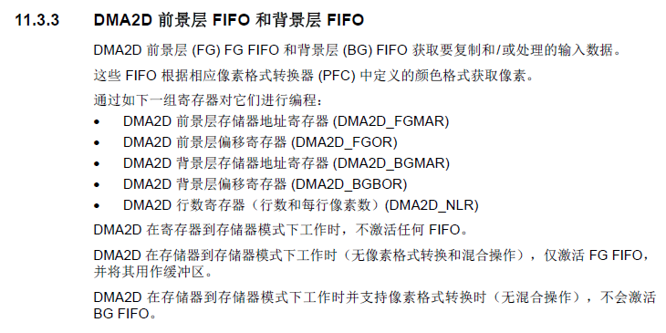
可以看到FG和BG是输入数据源,所以这些是对输入数据的设置
 /**

   * @brief  Start the DMA2D Transfer.

   * @param  hdma2d:     pointer to a DMA2D_HandleTypeDef structure that contains

   *                     the configuration information for the DMA2D.

   * @param  pdata:      Configure the source memory Buffer address if

   *                     the memory to memory or memory to memory with pixel format

   *                     conversion DMA2D mode is selected, and configure

   *                     the color value if register to memory DMA2D mode is selected.

   * @param  DstAddress: The destination memory Buffer address.

   * @param  Width:      The width of data to be transferred from source to destination.

   * @param  Height:      The height of data to be transferred from source to destination.

   * @retval HAL status

   */

 HAL_StatusTypeDef HAL_DMA2D_Start(DMA2D_HandleTypeDef *hdma2d, uint32_t pdata, uint32_t DstAddress, uint32_t Width,  uint32_t Height)

 {

   /* Process locked */

   __HAL_LOCK(hdma2d);

   /* Change DMA2D peripheral state */

   hdma2d->State = HAL_DMA2D_STATE_BUSY;

   /* Check the parameters */

   assert_param(IS_DMA2D_LINE(Height));

   assert_param(IS_DMA2D_PIXEL(Width));

   /* Disable the Peripheral */

   __HAL_DMA2D_DISABLE(hdma2d);

   /* Configure the source, destination address and the data size */

   DMA2D_SetConfig(hdma2d, pdata, DstAddress, Width, Height);

   /* Enable the Peripheral */

   __HAL_DMA2D_ENABLE(hdma2d);

   return HAL_OK;

 }
HAL_DMA2D_Start
 /**

   * @brief  Set the DMA2D Transfer parameter.

   * @param  hdma2d:     pointer to a DMA2D_HandleTypeDef structure that contains

   *                     the configuration information for the specified DMA2D.

   * @param  pdata:      The source memory Buffer address

   * @param  DstAddress: The destination memory Buffer address

   * @param  Width:      The width of data to be transferred from source to destination.

   * @param  Height:     The height of data to be transferred from source to destination.

   * @retval HAL status

   */

 static void DMA2D_SetConfig(DMA2D_HandleTypeDef *hdma2d, uint32_t pdata, uint32_t DstAddress, uint32_t Width, uint32_t Height)

 {

   uint32_t tmp = ;

   uint32_t tmp1 = ;

   uint32_t tmp2 = ;

   uint32_t tmp3 = ;

   uint32_t tmp4 = ;

   tmp = Width << ;

   /* Configure DMA2D data size */

   hdma2d->Instance->NLR = (Height | tmp);

   /* Configure DMA2D destination address */

   hdma2d->Instance->OMAR = DstAddress;

   /* Register to memory DMA2D mode selected */

   if (hdma2d->Init.Mode == DMA2D_R2M)

   {

     tmp1 = pdata & DMA2D_OCOLR_ALPHA_1;

     tmp2 = pdata & DMA2D_OCOLR_RED_1;

     tmp3 = pdata & DMA2D_OCOLR_GREEN_1;

     tmp4 = pdata & DMA2D_OCOLR_BLUE_1;

     /* Prepare the value to be wrote to the OCOLR register according to the color mode */

     if (hdma2d->Init.ColorMode == DMA2D_ARGB8888)

     {

       tmp = (tmp3 | tmp2 | tmp1| tmp4);

     }

     else if (hdma2d->Init.ColorMode == DMA2D_RGB888)

     {

       tmp = (tmp3 | tmp2 | tmp4);

     }

     else if (hdma2d->Init.ColorMode == DMA2D_RGB565)

     {

       tmp2 = (tmp2 >> );

       tmp3 = (tmp3 >> );

       tmp4 = (tmp4 >>  );

       tmp  = ((tmp3 << ) | (tmp2 << ) | tmp4);

     }

     else if (hdma2d->Init.ColorMode == DMA2D_ARGB1555)

     {

       tmp1 = (tmp1 >> );

       tmp2 = (tmp2 >> );

       tmp3 = (tmp3 >> );

       tmp4 = (tmp4 >>  );

       tmp  = ((tmp3 << ) | (tmp2 << ) | (tmp1 << ) | tmp4);

     }

     else /* DMA2D_CMode = DMA2D_ARGB4444 */

     {

       tmp1 = (tmp1 >> );

       tmp2 = (tmp2 >> );

       tmp3 = (tmp3 >> );

       tmp4 = (tmp4 >>  );

       tmp  = ((tmp3 << ) | (tmp2 << ) | (tmp1 << ) | tmp4);

     }

     /* Write to DMA2D OCOLR register */

     hdma2d->Instance->OCOLR = tmp;

   }

   else /* M2M, M2M_PFC or M2M_Blending DMA2D Mode */

   {

     /* Configure DMA2D source address */

     hdma2d->Instance->FGMAR = pdata;

   }

 }
DMA2D_SetConfig
/* Configure DMA2D data size */
tmp = Width << 16;
hdma2d->Instance->NLR = (Height | tmp);
/* Configure DMA2D destination address */
hdma2d->Instance->OMAR = DstAddress;
/* Configure DMA2D source address */
hdma2d->Instance->FGMAR = pdata;
这里设置两边memory的地址与行数也就是数据量
DMA2D_NLR 与DMA2D_OMAR 前面一章介绍过
整个初始化流程结束,主要设置了output,源地址是FG
最后设置传输:
 /**

   * @brief  Polling for transfer complete or CLUT loading.

   * @param  hdma2d: pointer to a DMA2D_HandleTypeDef structure that contains

   *                 the configuration information for the DMA2D.

   * @param  Timeout: Timeout duration

   * @retval HAL status

   */

 HAL_StatusTypeDef HAL_DMA2D_PollForTransfer(DMA2D_HandleTypeDef *hdma2d, uint32_t Timeout)

 {

   uint32_t tmp, tmp1;

   uint32_t tickstart = ;

   /* Polling for DMA2D transfer */

   if((hdma2d->Instance->CR & DMA2D_CR_START) != )

   {

    /* Get tick */

    tickstart = HAL_GetTick();

     while(__HAL_DMA2D_GET_FLAG(hdma2d, DMA2D_FLAG_TC) == RESET)

     {

       tmp  = __HAL_DMA2D_GET_FLAG(hdma2d, DMA2D_FLAG_CE);

       tmp1 = __HAL_DMA2D_GET_FLAG(hdma2d, DMA2D_FLAG_TE);

       if((tmp != RESET) || (tmp1 != RESET))

       {

         /* Clear the transfer and configuration error flags */

         __HAL_DMA2D_CLEAR_FLAG(hdma2d, DMA2D_FLAG_CE);

         __HAL_DMA2D_CLEAR_FLAG(hdma2d, DMA2D_FLAG_TE);

         /* Change DMA2D state */

         hdma2d->State= HAL_DMA2D_STATE_ERROR;

         /* Process unlocked */

         __HAL_UNLOCK(hdma2d);

         return HAL_ERROR;

       }

       /* Check for the Timeout */

       if(Timeout != HAL_MAX_DELAY)

       {

         if((Timeout == )||((HAL_GetTick() - tickstart ) > Timeout))

         {

           /* Process unlocked */

           __HAL_UNLOCK(hdma2d);

           /* Update error code */

           hdma2d->ErrorCode |= HAL_DMA2D_ERROR_TIMEOUT;

           /* Change the DMA2D state */

           hdma2d->State= HAL_DMA2D_STATE_TIMEOUT;

           return HAL_TIMEOUT;

         }

       }

     }

   }

   /* Polling for CLUT loading */

   if((hdma2d->Instance->FGPFCCR & DMA2D_FGPFCCR_START) != )

   {

     /* Get tick */

     tickstart = HAL_GetTick();

     while(__HAL_DMA2D_GET_FLAG(hdma2d, DMA2D_FLAG_CTC) == RESET)

     {

       if((__HAL_DMA2D_GET_FLAG(hdma2d, DMA2D_FLAG_CAE) != RESET))

       {

         /* Clear the transfer and configuration error flags */

         __HAL_DMA2D_CLEAR_FLAG(hdma2d, DMA2D_FLAG_CAE);

         /* Change DMA2D state */

         hdma2d->State= HAL_DMA2D_STATE_ERROR;

         return HAL_ERROR;

       }

       /* Check for the Timeout */

       if(Timeout != HAL_MAX_DELAY)

       {

         if((Timeout == )||((HAL_GetTick() - tickstart ) > Timeout))

         {

           /* Update error code */

           hdma2d->ErrorCode |= HAL_DMA2D_ERROR_TIMEOUT;

           /* Change the DMA2D state */

           hdma2d->State= HAL_DMA2D_STATE_TIMEOUT;

           return HAL_TIMEOUT;

         }

       }

     }

   }

   /* Clear the transfer complete flag */

   __HAL_DMA2D_CLEAR_FLAG(hdma2d, DMA2D_FLAG_TC);

   /* Clear the CLUT loading flag */

   __HAL_DMA2D_CLEAR_FLAG(hdma2d, DMA2D_FLAG_CTC);

   /* Change DMA2D state */

   hdma2d->State = HAL_DMA2D_STATE_READY;

   /* Process unlocked */

   __HAL_UNLOCK(hdma2d);

   return HAL_OK;

 }
HAL_DMA2D_PollForTransfer
#define DMA2D_FLAG_CE DMA2D_ISR_CEIF /*!< Configuration Error Interrupt Flag */
#define DMA2D_FLAG_CTC DMA2D_ISR_CTCIF /*!< C-LUT Transfer Complete Interrupt Flag */
#define DMA2D_FLAG_CAE DMA2D_ISR_CAEIF /*!< C-LUT Access Error Interrupt Flag */
#define DMA2D_FLAG_TW DMA2D_ISR_TWIF /*!< Transfer Watermark Interrupt Flag */
#define DMA2D_FLAG_TC DMA2D_ISR_TCIF /*!< Transfer Complete Interrupt Flag */
#define DMA2D_FLAG_TE DMA2D_ISR_TEIF /*!< Transfer Error Interrupt Flag */
STM32F4 DMA2D_M2M_PFC的更多相关文章
- 使用STM32F4的CCM内存
使用STM32F4的CCM内存http://www.stmcu.org/module/forum/forum.php?mod=viewthread&tid=604814&fromuid ...
- STM32F4读写内部FLASH【使用库函数】
STM32F4Discovery开发帮使用的STM32F407VGT6芯片,内部FLASH有1M之多.平时写的代码,烧写完之后还有大量的剩余.有效利用这剩余的FLASH能存储不少数据.因此研究了一下S ...
- STM32F1和STM32F4 区别
STM32F4相对于STM32F1的改进不只一点点,为了便于初学者了解,我们比对相关资料将改进点进行了汇总. STM32F1和STM32F4 区别 (安富莱整理)u F1采用Crotex M3内 ...
- STM32F4 SPI2初始化及收发数据【使用库函数】
我的STM32F4 Discovery上边有一个加速度传感器LIS302DL.在演示工程中,ST的工程师使用这个传感器做了个很令人羡慕的东西:解算开发板的姿态.当开发板倾斜时候,处于最上边的LED点亮 ...
- 使用固件库操作STM32F4时的必要配置(转)
源:使用固件库操作STM32F4时的必要配置 使用STM32F4的固件库时,默认的晶振为25Mhz晶振,因此需要做一定的修改.之前因为一直没有注意这个问题,我捣腾了许久,发现工作时钟总是不对,查阅了一 ...
- STM32F4系统时钟配置及描述
STM32F4系统时钟配置及描述 stm32f407时钟配置方法(感觉很好,分享一下) STM32F4_RCC系统时钟配置及描述 STM32F4时钟设置分析 stm32f4 - 时钟树分析配置
- STM32F4时钟配置分析
//学习STM32F4的过程中关于时钟上面讲的比较好 特地转发与大家分享 STM32F4时钟设置分析 原文博客链接:http://blog.csdn.net/jdh99,作者:jdh,转载请注明. 环 ...
- STM32F4的FPU单元讲解
搞STM32F407单片机的时候 看见的关于STM32F4系列的FPU 单元讲解 比较精彩的博客 于是特意转载 和大家分享 转自:http://blog.renren.com/blog/256814 ...
- STM32F4中USB与PC双向通信
STM32F4系列处理器内部集成了USB-OTG控制器,在不要外部USB IC下就可以实现USB通信,最近两天看了下如何利用STM32的USB实现通信,记录下关键步骤: 1. 从http://www. ...
随机推荐
- msp430入门编程37
msp430中C语言的可移植--屏蔽实现细节
- Spring Cloud(8):Sleuth和Zipkin的使用
场景: 某大型电商网站基于微服务架构,服务模块有几十个. 某天,测试人员报告该网站响应速度过慢.排除了网络问题之后,发现很难进一步去排除故障. 那么:如何对微服务的链路进行监控呢? Sleuth: 一 ...
- Spring Boot使用MyBatis 3打印SQL的配置
普通Spring下的XML文件配置: <?xml version="1.0" encoding="UTF-8" ?> <!DOCTYPE co ...
- CEF3研究(四)之javascript集成
一.介绍 谷歌浏览器和CEF使用V8JavaScript Engine作为内容的JavaScript实现.在浏览器中的每个窗口都有它自己在的JS上下文提供作用域和在窗口中安全的执行JS代码.CEF暴露 ...
- Capture and report JavaScript errors with window.onerror
原文:https://blog.sentry.io/2016/01/04/client-javascript-reporting-window-onerror.html onerror is a sp ...
- VC++如何折叠代码
工具-选项,然后在文本编辑器,C/C++中的格式设置,把大纲语句块设置为True 这样之后,还是不能像C#一样使用region折叠代码,但是可以方法和if语句都会自动显示可以折叠. 使用#pr ...
- lightoj 1138 - Trailing Zeroes (III)【二分】
题目链接:http://lightoj.com/volume_showproblem.php? problem=1138 题意:问 N. 末尾 0 的个数为 Q 个的数是什么? 解法:二分枚举N,由于 ...
- js性能优化之函数节流(分流函数)
函数节流的原理 比如我们在window.onresize事件中要打印当前浏览器窗口的大小,在我们通过拖拽来改变窗口大小时候,打印窗口大小这个工作1s就运行了10次.而实际上我们只需要2次或者3次. 比 ...
- Swift基础一(代码)
import Foundation println("Hello, World!") var string1 = "Hello BeiJing" //定义一个变 ...
- MVC架构在游戏开发中的应用
一 定义 MVC即Model View Controller,是模型(model)-视图(view)-控制器(controller)的缩写. MVC是一种"前端"的设计模式. MV ...