VGA Output from STM32F4 Discovery board
VGA Output from STM32F4 Discovery board
I love the web!
There are so many cool projects out there, and some, with a tweak or two,
get me where I want to go quickly, saving a ton of time and effort.
Case in point: The Artektit page on VGA output using a 36-pin STM32.
The Artekit gang developed a minimalist VGA implementation using one of the boards they sell,
with a 72 MHz STM32F103 device on-board.
I say "minimalist" because it uses just the board and a VGA connector, but you get 800x600 monochrome VGA out.
Then they added code for doing simple graphics and text generation, and all VGA timing is done using DMA writes to an SPI channel.
Their design has negligible impact on processor resources,
so you could drop their VGA drivers into your project and see almost no hit to throughput.
Because of memory constraints in the chosen device, they only have room for 400x200 pixels.
They implement this by assigning a 10K frame buffer, then writing out the pixels as 200 lines of 50 bytes each.
Each pixel is sent twice and each line is sent three times.
The result satisfies the monitor's timing for 800x600 VGA, but the effective graphics resolution is 400x200.
Enter the STM32F4 Discovery board.
It has plenty of room for a full 800x600 frame buffer and runs far faster than the original '103 device.
All that is needed is to port their code from the '103 device to the STM32F4 processor and
modify it to display a full 800x600 monochrome VGA.
VGA output from a $15 board. With almost no CPU through-put hit.
What's not to like?
The porting effort
I started with a download of the Artekit files from the above link.
I have to say the code is impressive.
The comments told me most of what I needed to know, and the structure was well thought out.
I'm only addressing items I changed or added to the Artekit project.
Some of this won't make sense unless you also read through the Artekit page; you've been warned.
The first task was selecting the I/O pins to use on the S4D board.
Here is what I ended up with:
| Artekit | Discovery | Notes |
| PA1 | PA1 | Vertical sync |
| PA7 | PB5 | VGA pixel data (GREEN) |
| PA8 | PA8 | Horizontal sync |
| GND | GND | Ground |
That's it! Four wires and you're good.
I switched my pixel data output to PB5.
I needed a MOSI signal from SPI1 and my only choices that supported DMA channels
were PA8 and PB5, and PA8 was already assigned.
The VGA timing requirements are widely available on the web;
one of the best sites is TinyVGA.com, which has pages devoted to many of the VGA resolutions.
The Artekit code uses a 56 Hz refresh rate, and I stuck to that.
From the TinyVGA site, the important 800x600 56 Hz timing info is:
General timing
| Screen refresh rate | 56 Hz |
| Vertical refresh | 35.15625 kHz |
| Pixel freq. | 36.0 MHz |
Horizontal timing (line)
Polarity of horizontal sync pulse is positive.
| Scanline part | Pixels | Time [µs] |
| Visible area | 800 | 22.222222222222 |
| Front porch | 24 | 0.66666666666667 |
| Sync pulse | 72 | 2 |
| Back porch | 128 | 3.5555555555556 |
| Whole line | 1024 | 28.444444444444 |
Vertical timing (frame)
Polarity of vertical sync pulse is positive.
| Frame part | Lines | Time [ms] |
| Visible area | 600 | 17.066666666667 |
| Front porch | 1 | 0.028444444444444 |
| Sync pulse | 2 | 0.056888888888889 |
| Back porch | 22 | 0.62577777777778 |
| Whole frame | 625 | 17.777777777778 |
All of the setup for this timing happens in the file video.c.
The code uses two channels of TIM1.
Channel 1 generates the Hsync pulse and channel 2 generates the Hsync plus back porch pulse.
Additionally, TIM1 is set as the master for TIM2.
The code also uses two channels of TIM2.
Channel 2 generates the Vsync pulse and channel 3 generates the Vsync plus back porch pulse.
Because TIM2 is slaved to TIM1, it automatically fires in lock-step with events generated by TIM1,
ensuring that horizontal and vertical timing are properly synced.
Pixel data appears on MOSI of SPI1.
SPI1 is fed pixel data via DMA, which is triggered by completion of the Hsync plus back porch event on TIM1.
Each DMA transfer writes one line of pixel data to SPI1;
data appears on MOSI with no timing gaps.
When each DMA transfer completes, a small amount of code in the IRQ handler
updates the input pointer (M0AR) to point to either the next line of pixel data or,
if a full screen transfer just ended, the start of the frame buffer.
The IRQ handlers for DMA, TIM1 and TIM2 contain the only run-time code needed to keep the entire VGA output going;
we're talking about 10 lines of code total.
All work to generate timing and move the pixel data is handled automatically by the timers and the DMA subsystem.
The pixel frequency is fixed at 36 MHz, which in turn sets the SPI clock
and there are a limited number of prescalers in that clock range.
I set the MCU system clock to 144 MHz, then used a /2 prescaler to get the need pixel clock.
Because the S4D has a much larger RAM pool than the original device,
I expanded the frame buffer to hold a full 800x600 monochrome display.
I also made slight modifications to the IRQ handlers to allow for the expanded pixel stream
and larger number of horizontal lines.
Because the original Artekit code was so well laid out, these changes were obvious and easy.
I left the Artekit demo code intact.
The demo looks almost exactly as its creators left it, except the text appears in the upper-left corner rather than the center,
and the text is quite a bit smaller though perfectly readable.
Here is a picture of the hardware:
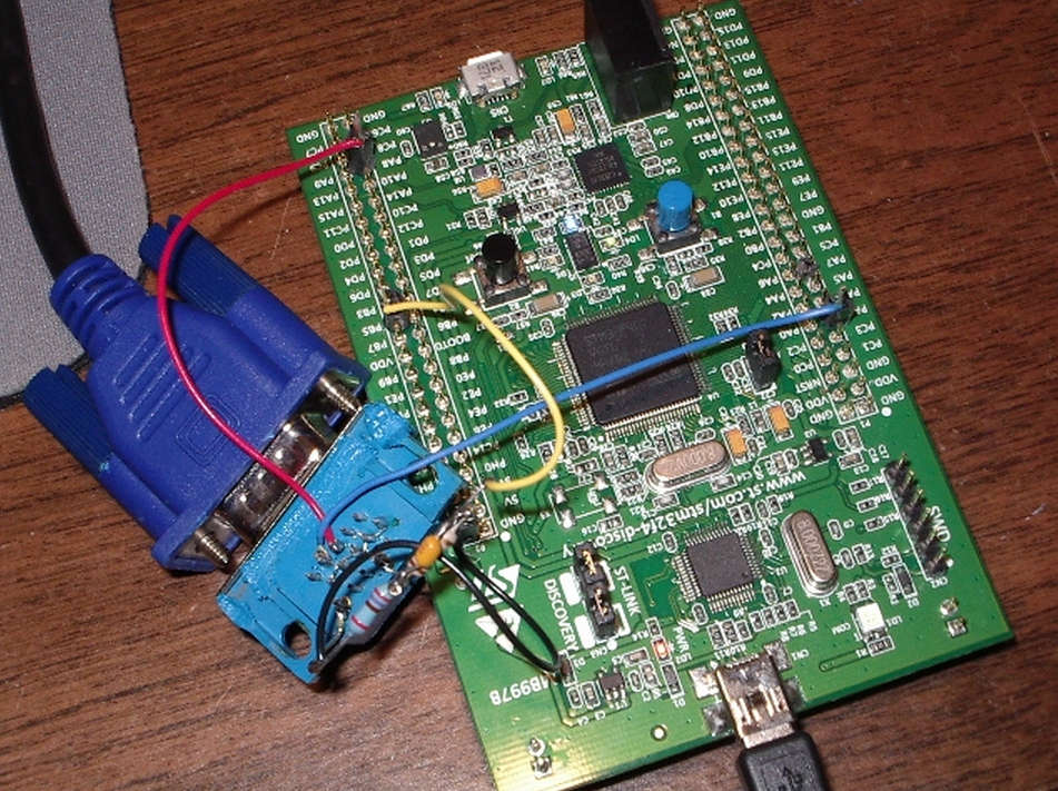
Yes, I know, it looks pretty nasty. I'll clean it up on the next hardware revision.
The photo does show one small mod I made to the wiring.
The Artekit writeup talks about using a resistor divider on the GREEN input.
Basically, I connected PB5 to a 120-ohm resistor, with a 47 pf capacitor wired across the resistor.
The other end of the resistor went to the GREEN input on the VGA connector.
Finally, I tied a 270-ohm resistor between the GREEN input and ground.
The Artekit page notes that they have driven a lot of monitors directly from the 3.3V output of their micro,
but it seemed to me using the resistor divider would be a better choice.
Here is a picture of the output on a Dell monitor:
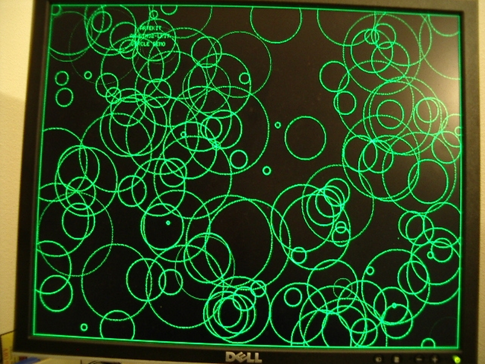
This is part of the Artekit demo program and gives you an idea of the display quality.
You can just make out the original Artekit text near the upper-left corner.
Issues
I hit a few snags during this effort, not the least of which was my unfamiliarity with VGA signal generation and use of the STM32 DMA subsystem.
One headache that came back almost immediately was the reason why I haven't done any STM32 code in several months.
The ST Micros Std Peripheral Driver library just sucks.
Whoever thought it was a good idea to wrap a simple register change in a function call needs
to develop a few time-critical apps on an ATtiny and see how far that concept gets you.
The only thing I've seen that's worse is Arduino code.
At one point in my development, I needed to push a stream of bytes out the SPI,
so I used one of the library's functions to write to the DR register.
The function introduced 250 ns gaps in the data stream.
Really? A 250 ns penalty for using your library call?
Not gonna happen.
I switched to a direct write to the register using a macro and the gap disappeared.
I see a lot of STM32 code on the web that uses library calls to initialize subsystems,
then switches to macros inside functional code. That's pretty much what I did here.
And I hated doing even that, because I just knew the linker probably brought in 8K or so of bloat from invoking these calls.
I ran into a problem with minor tearing (more like shimmering) of the display,
even when the display was not being modified by the code
(so this was not a issue with DMA accessing the frame buffer while the mainline code was accessing it).
I traced the problem to general memory accesses not related to the frame buffer.
I was using a spin-loop to generate delays, like this:
void sysDelayMs(u32 dly)

{

    int32_t                n;

    int32_t                j;

    for (n=; n<dly; n++)

    {

        for (j=; j<; j++)  ;        // rough guess, looking for 1 ms delay

    }

}
The above code caused the display to distort and tear while the mainline code was waiting for the delay to end.
If I moved the two timing variables into registers, like this:
void sysDelayMs(u32 dly)

{

    register int32_t                n;

    register int32_t                j;

    for (n=; n<dly; n++)

    {

        for (j=; j<; j++)  ;        // rough guess, looking for 1 ms delay

    }

}
the display became rock-solid and clean.
I don't know enough about the inner workings of the STM32F4 to know why the earlier code affected the display.
If anyone has an answer, please drop me an email.
Summary
I've bundled all of my code into a single zip file.
Like most of my embedded projects, I used Visual Studio 2008 as the IDE and the folder layout reflects that.
In order to set up this code to match your IDE, check through the Makefile (vga_artekit.mak);
the comments should help you as you edit the Makefile for your needs.
I'm assuming here that you already have CodeSourcery Lite++ installed on your machine
and you also have the ST Micros STM32F4 Discovery support files installed.
In my case, I installed the ST Micros code here:
C:\projects\STM32F4-Discovery_FW_V1.1.0\.
Note that I renamed any directories with spaces in their name to remove those spaces.
The spaces cause issues when I build within VS2008.
The code in this release is a working modification to the original Artekit code,
but I make no claims that this is bug-free or even high quality.
It works, it shows an excellent display, but I know it needs more time and work from me.
I'm releasing it so others can use it as a starting point for their projects.
As I update this code, I'll try and keep this page updated, as well.
I started this project because I wanted VGA display of text from an embedded microcontroller for the least effort,
smallest throughput hit, and lowest cost possible.
Thanks to Artekit and ST Micros, I now have the hardest part of that project done.
There's still plenty to do, of course.
I need to tweak the font file, wrap all of this code into a finished library,
create text and graphics APIs for my other projects to use, and probably some other stuff.
But I am much farther along on my project than I could have hoped to be without the headstart given by Artekit.
Thanks, guys, for some excellent code and a terrific project!
Here is the zip file of my project: vga_artekit.zip
VGA Output from STM32F4 Discovery board的更多相关文章
- One-wire Demo on the STM32F4 Discovery Board
One-wire Demo on the STM32F4 Discovery Board Some of the devs at work were struggling to get their s ...
- A CANBus Tiny Network without Transceiver ICs : STM32F4 Discovery
Sometimes you have a CAN equipped processor on a low cost board but it has no CAN transceiver chips. ...
- The STM32F746G-DISCO discovery board -- MBED
https://developer.mbed.org/platforms/ST-Discovery-F746NG/ Microcontroller features STM32F46NGH6 in T ...
- 使用36-pin的STM32输出VGA, VGA output using a 36-pin STM32
使用36-pin的STM32输出VGA 手头上有个项目需要通过单片机来控制将图像显示在LCD上,在网上搜了一阵子,发现都是使用的FPGA做的, 开始自己对FPGA不是很熟,一直在用的也是ARM系列的, ...
- STM32F4 HAL Composite USB Device Example : CDC + MSC
STM32F4 USB Composite CDC + MSC I'm in the process of building a USB composite CDC + MSC device on t ...
- 【ST开发板评测】使用Python来开发STM32F411
前言 板子申请了也有一段时间了,也快到评测截止时间了,想着做点有意思的东西,正好前一段时间看到过可以在MCU上移植MicroPython的示例,就自己尝试一下,记录移植过程. MicroPython是 ...
- CRT/LCD/VGA Information and Timing
彩色阴极射线管的剖面图: 1. 电子QIANG Three Electron guns (for red, green, and blue phosphor dots)2. 电子束 Electron ...
- CRT/LCD/VGA Information and Timing【转】
转自:http://www.cnblogs.com/shangdawei/p/4760933.html 彩色阴极射线管的剖面图: 1. 电子QIANG Three Electron guns (for ...
- STM32F4 SPI2初始化及收发数据【使用库函数】
我的STM32F4 Discovery上边有一个加速度传感器LIS302DL.在演示工程中,ST的工程师使用这个传感器做了个很令人羡慕的东西:解算开发板的姿态.当开发板倾斜时候,处于最上边的LED点亮 ...
随机推荐
- 20155338 2016-2017-2 《Java程序设计》第7周学习总结
20155338 2016-2017-2 <Java程序设计>第7周学习总结 教材学习内容总结 本周学习了第十二章和第十三章的内容,我重点学习了第十三章时间与日期的相关内容. 时间的度量: ...
- HDU 1241 Oil Deposits DFS搜索题
题目大意:给你一个m*n的矩阵,里面有两种符号,一种是 @ 表示这个位置有油田,另一种是 * 表示这个位置没有油田,现在规定相邻的任意块油田只算一块油田,这里的相邻包括上下左右以及斜的的四个方向相邻的 ...
- HTTP Methods
简介 HTTP 定义了一组请求方法,以表明要对给定资源执行的操作.指示针对给定资源要执行的期望动作, 虽然他们也可以是名词,但这些请求方法有时被称为HTTP动词.每一个请求方法都实现了不同的语义,但一 ...
- yui压缩JS和CSS文件
CSS和JS文件经常需要压缩,比如我们看到的XX.min.js是经过压缩的JS. 压缩文件第一个是可以减小文件大小,第二个是对于JS文件,默认会去掉所有的注释,而且会去掉所有的分号,也会将我们的一些参 ...
- 【CTF WEB】命令执行
命令执行 找到题目中的KEY KEY为八位随机字符数字,例如key:1234qwer.提交1234qwer 即可. 漏洞代码 <?php system("ping -c 2 " ...
- 数据库SQL语句性能优化
选择最有效率的表名顺序 ORACLE的解析器按照从右到左的顺序处理FROM子句中的表名,FROM子句中写在最后的表(基础表 driving table)将被最先处理,在FROM子句中包含多个表的情况下 ...
- redis 配置文件翻译
2014年6月24日 17:29:11 include 如果有其它配置文件,可以使用 include 指令 ####通用配置 daemonize 默认的redis不会以守护进程运行,需要这样的话可 ...
- java 缺憾:异常的丢失
一.java的异常实现也是又缺陷的,异常作为程序出错的标志决不能被忽略,但它还是可能被轻易地忽略.下了可以看到前一个异常还没处理就抛出下一个异常,没有catch捕获异常,它被finally抛出下一个异 ...
- 【军哥谈CI框架】之CI中集成百度UEditor
Hello,各位亲,新的一周来临啦,很高兴这么快又跟大家伙见面!话说上一回,军哥带大家用JQuery写了一个城市级联菜单的例子 ,不知道亲们学会了多少,是否自己可以独立写出来了呢. 军哥很是期待大家学 ...
- MVC4是不是类似于html页+ashx页之间用JSON通过AJAX交换数据这种方式、?
不是,可以讲mvc模式是借鉴于java下面的mvc开发模式,为开发者公开了更多的内容和控制,更易于分工合作,与单元测试,借用官方的说法:MVC (Model.View.Controller)将一个We ...