
MSTP+ VRRP 交换机的 配置过程

配置思路
采用以下思路配置:
1.在处于环形网络中的交换设备上配置MSTP基本功能,包括:
a.配置MST域并创建多实例,配置VLAN2映射到MSTI1,VLAN3映射到MSTI2,实现流量的负载分担。
b.在MST域内,配置各实例的根桥与备份根桥。
c.配置各实例中某端口的路径开销值,实现将该端口阻塞。
d.使能MSTP,实现破除环路,包括:
•设备全局使能MSTP。
•除与终端设备相连的端口外,其他端口使能MSTP。
说明:
与终端相连的端口不用参与MSTP计算,建议将其设置为边缘端口。
2.配置保护功能,实现对设备或链路的保护。例如:在各实例的根桥设备指定端口配置根保护功能。
3.配置设备的二层转发功能。
4.配置各设备端口IP地址及路由协议,使各设备间网络层连通。
说明:
本例中SwitchA和SwitchB需要支持VRRP和OSPF,有关VRRP和OSPF的支持形态,请参见相关章节。
5.在SwitchA和SwitchB上创建VRRP备份组1和VRRP备份组2,在备份组1中,配置SwitchA为Master设备,SwitchB为Backup设备;
在备份组2中,配置SwitchB为Master设备,SwitchA为Backup设备,实现流量的负载均衡。
______________________
1,
1.在处于环形网络中的交换设备上配置MSTP基本功能,包括:
a.配置MST域并创建多实例,配置VLAN2映射到MSTI1,VLAN3映射到MSTI2,实现流量的负载分担。
[SwitchA] [SwitchB] [SwitchC]
[SwitchA] stp region-configuration
[SwitchA-mst-region] region-name RG1
[SwitchA-mst-region] instance 1 vlan 2
[SwitchA-mst-region] instance 2 vlan 3
[SwitchA-mst-region] active region-configuration
[SwitchA-mst-region] quit
b.在MST域内,配置各实例的根桥与备份根桥。
c.配置各实例中某端口的路径开销值,实现将该端口阻塞。
d.使能MSTP,实现破除环路,包括:
•设备全局使能MSTP。
•除与终端设备相连的端口外,其他端口使能MSTP。
说明:
与终端相连的端口不用参与MSTP计算,建议将其设置为边缘端口。
c.配置实例MSTI1和MSTI2中将要被阻塞端口的路径开销值大于缺省值
说明:
•端口路径开销值取值范围由路径开销计算方法决定,这里选择使用华为计算方法为例,配置实例MSTI1和MSTI2中将被阻塞端口的路径开销值为20000。
•同一网络内所有交换设备的端口路径开销应使用相同的计算方法。
# 配置SwitchA的端口路径开销计算方法为华为计算方法。
[SwitchA] stp pathcost-standard legacy# 配置SwitchB的端口路径开销计算方法为华为计算方法。
[SwitchB] stp pathcost-standard legacy# 配置SwitchC的端口路径开销计算方法为华为计算方法,将端口GE0/0/1在实例MSTI2中的路径开销值配置为20000,将端口GE0/0/4在实例MSTI1中的路径开销值配置为20000。
[SwitchC] stp pathcost-standard legacy
[SwitchC] interface gigabitethernet 0/0/1
[SwitchC-GigabitEthernet0/0/1] stp instance 2 cost 20000 #让 instance 2的vlan3 走 0/0/4端口
[SwitchC-GigabitEthernet0/0/1] quit
[SwitchC] interface gigabitethernet 0/0/4
[SwitchC-GigabitEthernet0/0/4] stp instance 1 cost 20000 #让 instance1 的vlan2 走 0/0/1端口
[SwitchC-GigabitEthernet0/0/4] quit
使能MSTP,实现破除环路
设备全局使能MSTP
# 在SwitchA上启动MSTP。
[SwitchA] stp enable
# 在SwitchB上启动MSTP。
[SwitchB] stp enable
# 在SwitchC上启动MSTP。
[SwitchC] stp enable
将与Host相连的端口设置为边缘端口
# 配置SwitchC端口GE0/0/2和GE0/0/3为边缘端口。
[SwitchC] interface gigabitethernet 0/0/2

[SwitchC-GigabitEthernet0/0/2] stp edged-port enable

[SwitchC-GigabitEthernet0/0/2] quit

[SwitchC] interface gigabitethernet 0/0/3

[SwitchC-GigabitEthernet0/0/3] stp edged-port enable

[SwitchC-GigabitEthernet0/0/3] quit
(可选)配置SwitchC的BPDU保护功能。
[SwitchC] stp bpdu-protection
将与Router相连的端口设置为边缘端口
# 配置SwitchA端口GE0/0/3为边缘端口。
[SwitchA] interface gigabitethernet 0/0/3

[SwitchA-GigabitEthernet0/0/3] stp edged-port enable

[SwitchA-GigabitEthernet0/0/3] quit
(可选)配置SwitchA的BPDU保护功能。
[SwitchA] stp bpdu-protection
# 配置SwitchB端口GE0/0/3为边缘端口。
[SwitchB] interface gigabitethernet 0/0/3

[SwitchB-GigabitEthernet0/0/3] stp edged-port enable

[SwitchB-GigabitEthernet0/0/3] quit
(可选)配置SwitchB的BPDU保护功能。
[SwitchB] stp bpdu-protection
说明:
如果与边缘端口相连的是使能了STP功能的网络设备,配置BPDU保护功能后,如果边缘端口收到BPDU报文,边缘端口将会被shutdown,边缘端口属性不变。
- 配置保护功能,如在各实例的根桥设备的指定端口配置根保护功能
# 在SwitchA端口GE0/0/1上启动根保护。
[SwitchA] interface gigabitethernet 0/0/1

[SwitchA-GigabitEthernet0/0/1] stp root-protection

[SwitchA-GigabitEthernet0/0/1] quit
# 在SwitchB端口GE0/0/1上启动根保护。
[SwitchB] interface gigabitethernet 0/0/1

[SwitchB-GigabitEthernet0/0/1] stp root-protection

[SwitchB-GigabitEthernet0/0/1] quit - 配置处于环网中的设备的二层转发功能
在交换设备SwitchA、SwitchB、SwitchC上创建VLAN2~3
# 在SwitchA上创建VLAN2~3。
[SwitchA] vlan batch 2 to 3
# 在SwitchB上创建VLAN2~3。
[SwitchB] vlan batch 2 to 3
# 在SwitchC上创建VLAN2~3。
[SwitchC] vlan batch 2 to 3
将交换设备上接入环路中的端口加入VLAN
# 将SwitchA端口GE0/0/1加入VLAN。
[SwitchA] interface gigabitethernet 0/0/1

[SwitchA-GigabitEthernet0/0/1] port link-type trunk

[SwitchA-GigabitEthernet0/0/1] port trunk allow-pass vlan 2 to 3

[SwitchA-GigabitEthernet0/0/1] quit
# 将SwitchA端口GE0/0/2加入VLAN。
[SwitchA] interface gigabitethernet 0/0/2

[SwitchA-GigabitEthernet0/0/2] port link-type trunk

[SwitchA-GigabitEthernet0/0/2] port trunk allow-pass vlan 2 to 3

[SwitchA-GigabitEthernet0/0/2] quit
# 将SwitchB端口GE0/0/1加入VLAN。
[SwitchB] interface gigabitethernet 0/0/1

[SwitchB-GigabitEthernet0/0/1] port link-type trunk

[SwitchB-GigabitEthernet0/0/1] port trunk allow-pass vlan 2 to 3

[SwitchB-GigabitEthernet0/0/1] quit
# 将SwitchB端口GE0/0/2加入VLAN。
[SwitchB] interface gigabitethernet 0/0/2

[SwitchB-GigabitEthernet0/0/2] port link-type trunk

[SwitchB-GigabitEthernet0/0/2] port trunk allow-pass vlan 2 to 3

[SwitchB-GigabitEthernet0/0/2] quit
# 将SwitchC端口GE0/0/1加入VLAN。
[SwitchC] interface gigabitethernet 0/0/1

[SwitchC-GigabitEthernet0/0/1] port link-type trunk

[SwitchC-GigabitEthernet0/0/1] port trunk allow-pass vlan 2 to 3

[SwitchC-GigabitEthernet0/0/1] quit
# 将SwitchC端口GE0/0/2加入VLAN。
[SwitchC] interface gigabitethernet 0/0/2

[SwitchC-GigabitEthernet0/0/2] port link-type access

[SwitchC-GigabitEthernet0/0/2] port default vlan 2

[SwitchC-GigabitEthernet0/0/2] quit
# 将SwitchC端口GE0/0/3加入VLAN。
[SwitchC] interface gigabitethernet 0/0/3

[SwitchC-GigabitEthernet0/0/3] port link-type access

[SwitchC-GigabitEthernet0/0/3] port default vlan 3

[SwitchC-GigabitEthernet0/0/3] quit
# 将SwitchC端口GE0/0/4加入VLAN。
[SwitchC] interface gigabitethernet 0/0/4

[SwitchC-GigabitEthernet0/0/4] port link-type trunk

[SwitchC-GigabitEthernet0/0/4] port trunk allow-pass vlan 2 to 3

[SwitchC-GigabitEthernet0/0/4] quit
- 验证配置结果
经过以上配置,在网络计算稳定后,执行以下操作,验证配置结果。
说明:
本配置举例以实例1和实例2为例,因此不用关注实例0中端口的状态。
# 在SwitchA上执行display stp brief命令,查看端口状态和端口的保护类型,结果如下:
[SwitchA] display stp brief

 MSTID      Port                        Role  STP State       Protection

   0        GigabitEthernet0/0/1DESI  FORWARDING      ROOT

   0        GigabitEthernet0/0/2DESI  FORWARDING      NONE

   1        GigabitEthernet0/0/1        DESI  FORWARDING      ROOT

   1        GigabitEthernet0/0/2        DESI  FORWARDING      NONE

   2        GigabitEthernet0/0/1        DESI  FORWARDING      ROOT

   2        GigabitEthernet0/0/2        ROOT  FORWARDING      NONE
在MSTI1中,由于SwitchA是根桥,SwitchA的端口GE0/0/2和GE0/0/1成为指定端口。在MSTI2中,SwitchA的端口GE0/0/1成为指定端口,端口GE0/0/2成为根端口。
# 在SwitchB上执行display stp brief命令,结果如下:
[SwitchB] display stp brief

 MSTID      Port                        Role  STP State       Protection

   0        GigabitEthernet0/0/1DESI  FORWARDING      ROOT

   0        GigabitEthernet0/0/2ROOT  FORWARDING      NONE

   1        GigabitEthernet0/0/1        DESI  FORWARDING      ROOT

   1        GigabitEthernet0/0/2        ROOT  FORWARDING      NONE

   2        GigabitEthernet0/0/1        DESI  FORWARDING      ROOT

   2        GigabitEthernet0/0/2        DESI  FORWARDING      NONE
在MSTI2中,由于SwitchB是根桥,端口GE0/0/1和GE0/0/2在MSTI2中成为指定端口。在MSTI1中,SwitchB的端口GE0/0/1成为指定端口,端口GE0/0/2成为根端口。
# 在SwitchC上执行display stp interface brief命令,结果如下:
[SwitchC] display stp interface gigabitethernet 0/0/1 brief

 MSTID      Port                        Role  STP State       Protection

   0        GigabitEthernet0/0/1ROOT  FORWARDING      NONE

   1        GigabitEthernet0/0/1        ROOT  FORWARDING      NONE

   2        GigabitEthernet0/0/1        ALTE  DISCARDING      NONE
[SwitchC] display stp interface gigabitethernet 0/0/4 brief
MSTID Port Role STP State Protection
0 GigabitEthernet0/0/4ALTE DISCARDING NONE
1 GigabitEthernet0/0/4 ALTE DISCARDING NONE
2 GigabitEthernet0/0/4 ROOT FORWARDING NONESwitchC的端口GE0/0/1在MSTI1中为根端口,在MSTI2中被阻塞。SwitchC的另一个端口GE0/0/4,在MSTI1中被阻塞,在MSTI2中为根端口。
- 配置设备间的网络互连
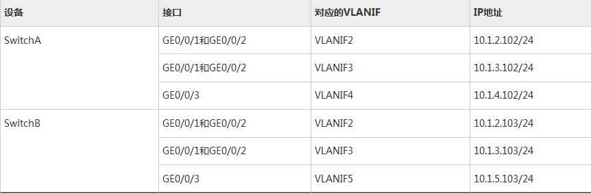
# 配置设备各端口的IP地址,以SwitchA为例。SwitchB的配置与SwitchA类似,详见配置文件。
[SwitchA] vlan batch 4

[SwitchA] interface gigabitethernet 0/0/3

[SwitchA-GigabitEthernet0/0/3] port link-type trunk

[SwitchA-GigabitEthernet0/0/3] port trunk allow-pass vlan 4

[SwitchA-GigabitEthernet0/0/3] quit

[SwitchA] interface vlanif 2

[SwitchA-Vlanif2] ip address 10.1.2.102 24

[SwitchA-Vlanif2] quit

[SwitchA] interface vlanif 3

[SwitchA-Vlanif3] ip address 10.1.3.102 24

[SwitchA-Vlanif3] quit

[SwitchA] interface vlanif 4

[SwitchA-Vlanif4] ip address 10.1.4.102 24

[SwitchA-Vlanif4] quit
# 配置SwitchA、SwitchB和路由器间采用OSPF协议进行互连。以SwitchA为例,SwitchB的配置与SwitchA类似,详见配置文件。
[SwitchA] ospf 1

[SwitchA-ospf-1] area 0

[SwitchA-ospf-1-area-0.0.0.0] network 10.1.2.0 0.0.0.255

[SwitchA-ospf-1-area-0.0.0.0] network 10.1.3.0 0.0.0.255

[SwitchA-ospf-1-area-0.0.0.0] network 10.1.4.0 0.0.0.255

[SwitchA-ospf-1-area-0.0.0.0] quit

[SwitchA-ospf-1] quit - 配置VRRP备份组
# 在SwitchA和SwitchB上创建VRRP备份组1,配置SwitchA的优先级为120,抢占延时为20秒,作为Master设备;SwitchB的优先级为缺省值,作为Backup设备。
[SwitchA] interface vlanif 2

[SwitchA-Vlanif2] vrrp vrid 1 virtual-ip 10.1.2.100

[SwitchA-Vlanif2] vrrp vrid 1 priority 120

[SwitchA-Vlanif2] vrrp vrid 1 preempt-mode timer delay 20

[SwitchA-Vlanif2] quit
[SwitchB] interface vlanif 2
[SwitchB-Vlanif2] vrrp vrid 1 virtual-ip 10.1.2.100
[SwitchB-Vlanif2] quit# 在SwitchA和SwitchB上创建VRRP备份组2,配置SwitchB的优先级为120,抢占延时为20秒,作为Master设备;SwitchA的优先级为缺省值,作为Backup设备。
[SwitchB] interface vlanif 3

[SwitchB-Vlanif3] vrrp vrid 2 virtual-ip 10.1.3.100

[SwitchB-Vlanif3] vrrp vrid 2 priority 120

[SwitchB-Vlanif3] vrrp vrid 2 preempt-mode timer delay 20

[SwitchB-Vlanif3] quit
[SwitchA] interface vlanif 3
[SwitchA-Vlanif3] vrrp vrid 2 virtual-ip 10.1.3.100
[SwitchA-Vlanif3] quit# 配置主机HostA的缺省网关为备份组1的虚拟IP地址10.1.2.100,配置主机HostB的缺省网关为备份组2的虚拟IP地址10.1.3.100。
- 验证配置结果
# 完成上述配置后,在SwitchA上执行display vrrp命令,可以看到SwitchA在备份组1中作为Master设备,在备份组2中作为Backup设备。
[SwitchA] display vrrp

  Vlanif2 | Virtual Router 1

    State : Master

    Virtual IP : 10.1.2.100

    Master IP : 10.1.2.102

    PriorityRun : 120

    PriorityConfig : 120

    MasterPriority : 120

    Preempt : YES   Delay Time : 20 s

    TimerRun : 1 s

    TimerConfig : 1 s

    Auth type : NONE

    Virtual MAC : 0000-5e00-0101

    Check TTL : YES

    Config type : normal-vrrp

    Backup-forward : disabled

    Create time :2012-05-11 11:39:18

    Last change time :2012-05-26 11:38:58

  Vlanif3 | Virtual Router 2

    State : Backup

    Virtual IP : 10.1.3.100

    Master IP : 10.1.3.103

    PriorityRun : 100

    PriorityConfig : 100

    MasterPriority : 120

    Preempt : YES   Delay Time : 0 s

    TimerRun : 1 s

    TimerConfig : 1 s

    Auth type : NONE

    Virtual MAC : 0000-5e00-0102

    Check TTL : YES

    Config type : normal-vrrp

    Backup-forward : disabled

    Create time :2012-05-11 11:40:18

    Last change time :2012-05-26 11:48:58
# 在SwitchB上执行display vrrp命令,可以看到SwitchB在备份组1中作为Backup设备,在备份组2中作为Master设备。
[SwitchB] display vrrp

  Vlanif2 | Virtual Router 1

    State : Backup

    Virtual IP : 10.1.2.100

    Master IP : 10.1.2.102

    PriorityRun : 100

    PriorityConfig : 100

    MasterPriority : 120

    Preempt : YES   Delay Time : 0 s

    TimerRun : 1 s

    TimerConfig : 1 s

    Auth type : NONE

    Virtual MAC : 0000-5e00-0101

    Check TTL : YES

    Config type : normal-vrrp

    Backup-forward : disabled

    Create time :2012-05-11 11:39:18

    Last change time :2012-05-26 11:38:58

  Vlanif3 | Virtual Router 2

    State : Master

    Virtual IP : 10.1.3.100

    Master IP : 10.1.3.103

    PriorityRun : 120

    PriorityConfig : 120

    MasterPriority : 120

    Preempt : YES   Delay Time : 20 s

    TimerRun : 1 s

    TimerConfig : 1 s

    Auth type : NONE

    Virtual MAC : 0000-5e00-0102

    Check TTL : YES

    Config type : normal-vrrp

    Backup-forward : disabled

    Create time :2012-05-11 11:40:18

    Last change time :2012-05-26 11:48:58
配置文件
SwitchA的配置文件
#

sysname SwitchA

#

vlan batch 2 to 4

#

stp instance 1 root primary

stp instance 2 root secondary

stp bpdu-protection

stp pathcost-standard legacy

#

stp region-configuration

 region-name RG1

 instance 1 vlan 2

 instance 2 vlan 3

 active region-configuration

#

interface Vlanif2

 ip address 10.1.2.102 255.255.255.0

 vrrp vrid 1 virtual-ip 10.1.2.100

 vrrp vrid 1 priority 120

 vrrp vrid 1 preempt-mode timer delay 20

#

interface Vlanif3

 ip address 10.1.3.102 255.255.255.0

 vrrp vrid 2 virtual-ip 10.1.3.100

#

interface Vlanif4

 ip address 10.1.4.102 255.255.255.0

#

interface GigabitEthernet0/0/1

 port link-type trunk

 port trunk allow-pass vlan 2 to 3

 stp root-protection

#

interface GigabitEthernet0/0/2

 port link-type trunk

 port trunk allow-pass vlan 2 to 3

#

interface GigabitEthernet0/0/3

 port link-type trunk

 port trunk allow-pass vlan 4

 stp edged-port enable

#

ospf 1

 area 0.0.0.0

  network 10.1.2.0 0.0.0.255

  network 10.1.3.0 0.0.0.255

  network 10.1.4.0 0.0.0.255

#

return
SwitchB的配置文件
#

sysname SwitchB

#

vlan batch 2 to 3 5

#

stp instance 1 root secondary

stp instance 2 root primary

stp bpdu-protection

stp pathcost-standard legacy

#

stp region-configuration

 region-name RG1

 instance 1 vlan 2

 instance 2 vlan 3

 active region-configuration

#

interface Vlanif2

 ip address 10.1.2.103 255.255.255.0

 vrrp vrid 1 virtual-ip 10.1.2.100

#

interface Vlanif3

 ip address 10.1.3.103 255.255.255.0

 vrrp vrid 2 virtual-ip 10.1.3.100

 vrrp vrid 2 priority 120

 vrrp vrid 2 preempt-mode timer delay 20

#

interface Vlanif5

 ip address 10.1.5.103 255.255.255.0

#

interface GigabitEthernet0/0/1

 port link-type trunk

 port trunk allow-pass vlan 2 to 3

 stp root-protection

#

interface GigabitEthernet0/0/2

 port link-type trunk

 port trunk allow-pass vlan 2 to 3

#

interface GigabitEthernet0/0/3

 port link-type trunk

 port trunk allow-pass vlan 5

 stp edged-port enable

#

ospf 1

 area 0.0.0.0

  network 10.1.2.0 0.0.0.255

  network 10.1.3.0 0.0.0.255

  network 10.1.5.0 0.0.0.255

#

return
SwitchC的配置文件
#

sysname SwitchC

#

vlan batch 2 to 3

#

stp bpdu-protection

stp pathcost-standard legacy

#

stp region-configuration

 region-name RG1

 instance 1 vlan 2

 instance 2 vlan 3

 active region-configuration

#

interface GigabitEthernet0/0/1

 port link-type trunk

 port trunk allow-pass vlan 2 to 3

 stp instance 2 cost 20000

#

interface GigabitEthernet0/0/2

 port link-type access

 port default vlan 2

 stp edged-port enable

#

interface GigabitEthernet0/0/3

 port link-type access

 port default vlan 3

 stp edged-port enable

#

interface GigabitEthernet0/0/4

 port link-type trunk

 port trunk allow-pass vlan 2 to 3

 stp instance 1 cost 20000

#

return
MSTP+ VRRP 交换机的 配置过程的更多相关文章
- 华为交换机MSTP+VRRP配置实例说明文档
华为交换机MSTP+VRRP配置实例说明文档 拓扑图 IP地址规划表 设备名称 设备接口 对端设备 对端接口 VLAN VLAN /接口地址 备注 SW0 GE0/0/23 SW2 GE0/0/23 ...
- ESXi与物理交换机静态链路聚合配置过程中的小陷阱
作者:陆斌文章来自微信公众号:平台人生 内容简介:ESXi与物理交换机之间配置静态链路聚合时,因为静态链路聚合的特点,在进行down网卡和从虚拟交换机移除网卡的操作时,可能会无法完成故障流量切换,影响 ...
- MSTP多实例的配置
MSTP多实例的配置 这次实验主要是为了加强对stp生成树协议中,RP(根端口),DP(指定端口),AP(阻塞端口)的判断方法:虽然很多时候不需要我们人工判断,因为当我们吧所有的配置好之后,然后开启生 ...
- MSTP多生成树的配置
STP的不足 STP协议虽然能够解决环路问题,但是由于网络拓扑收敛较慢,影响了用户通信质量 而且如果网络中的拓扑结构频繁变化,网络也会随之频繁失去连通性,从而导致用户通信频繁中断 RSTP对STP的改 ...
- Cisco Packet Tracer 交换机 2950-24 配置
大步骤1:设置交换机名字.特权模式口令.本地管理口令.远程登入口令 Switch>en 进入特权模式 Switch#conf t 进去全局配置模式 Enter configurati ...
- Ip-san 配置过程
1:SAN的定义 SAN是storage area network(存储区域网络)的简写,早期的san采用的是光纤通道技术,后期当iscsi协议出现以后,为了区分两者,就划分了IP SAN和FC SA ...
- 记一次华为eNSP设备网络项目基本配置过程
下图为综合项目示例图,详细命令见图下: 屏蔽垃圾信息undo terminal monitorundo terminal trappingundo terminal loggingundo termi ...
- 网络拓扑实例10:MSTP+VRRP组合组网
组网图形 MSTP+VRRP组合简介 网络中部署VRRP负载分担时,多台设备同时承担业务,每个虚拟设备都包括一个Master设备和若干个Backup设备.如果为了接入备份需要同时部署冗余链路,则需要部 ...
- Linux LVM逻辑卷配置过程详解
许多Linux使用者安装操作系统时都会遇到这样的困境:如何精确评估和分配各个硬盘分区的容量,如果当初评估不准确,一旦系统分区不够用时可能不得不备份.删除相关数据,甚至被迫重新规划分区并重装操作系统,以 ...
随机推荐
- CVE-2017-12615和CVE-2017-12616
Tomcat代码执行漏洞分析测试 1. 漏洞花絮 2017年9月19日,Apache Tomcat官方确认并修复了两个高危漏洞,漏洞CVE编号:CVE-2017-12615和CVE-20 ...
- 学习笔记TF037:实现强化学习策略网络
强化学习(Reinforcement Learing),机器学习重要分支,解决连续决策问题.强化学习问题三概念,环境状态(Environment State).行动(Action).奖励(Reward ...
- JS 格式化日期时间
方法一: // 对Date的扩展,将 Date 转化为指定格式的String // 月(M).日(d).小时(h).分(m).秒(s).季度(q) 可以用 1-2 个占位符, // 年(y)可以用 1 ...
- 一些有用的Java学习资料
Better Java,一些好的Java实践 Google Java Style Guide 30个Java编程技巧 JDK8新增语法特性简介,对Java8中新增的函数接口.Lambda表达式.方法引 ...
- react使用ant-design组件库
新建项目并引入组件 1,全局安装脚手架 npm install -g create-react-app 2,新建项目 create-react-app reactantd 3,安装组件 npm ins ...
- base64图片内容下载转为图片保存
网页中的base64图片内容下载后,利用PIL转为图片保存 from skimage.io import imread from PIL import Image from cStringIO imp ...
- ajax基本原理
- Handling Touches - RN3
1. basic button format: <tag event caption /> <Button onPress={{}} title="I am button& ...
- centos7安装redmine3.4
前言:安装要求 Ruby解释器 给定Redmine版本所需的Ruby版本是: Redmine版本 支持的Ruby版本 使用Rails版本 4.0 ruby 2.2(2.2.2及更高版本),2.3,2. ...
- laravel中消息通知功能
以laravel5.5为例子,这个功能laravel自带的有: 1.生成表文件的migration文件,再migrate一下在数据库里生成表.命令为:php artisan notifications ...