Unused port adds a PWM/analog channel to a microcontroller
Low-cost, 8-bit, single-chip microcontrollers are stingy when it comes to on-chip PWM (pulse-width-modulation) resources. The use of a PWM resource often forces a designer to sacrifice a capture/compare or timer channel because the PWM channel shares the same on-chip hardware. This Design Idea describes how you can use an on-chip unused synchronous serial port to generate PWM signals and convert them to a slow-moving analog signal (Figure 1).
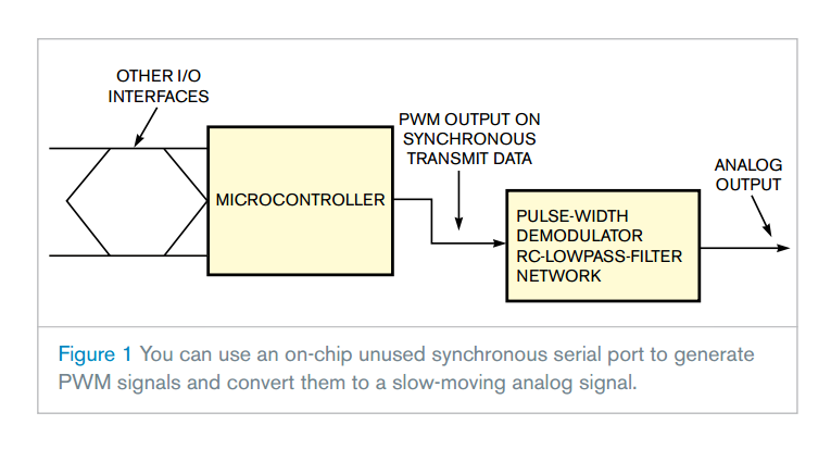
Many microcontroller-based stand-alone electronic units don’t use the synchronous serial port. Thus, you can use the microcontroller’s baud-rate generator and parallel-to-serial-converter blocks to generate bit patterns to form a 256-bit PWM pattern. You can then filter the PWM output with an RC filter to extract an analog signal (Reference 1). The synchronous communication is devoid of the start and stop bits of asynchronous mode, so the bit pattern can generate long periods of high or low level.
You can generate raw data with a decimal value of 165 using this concept (Figure 2).
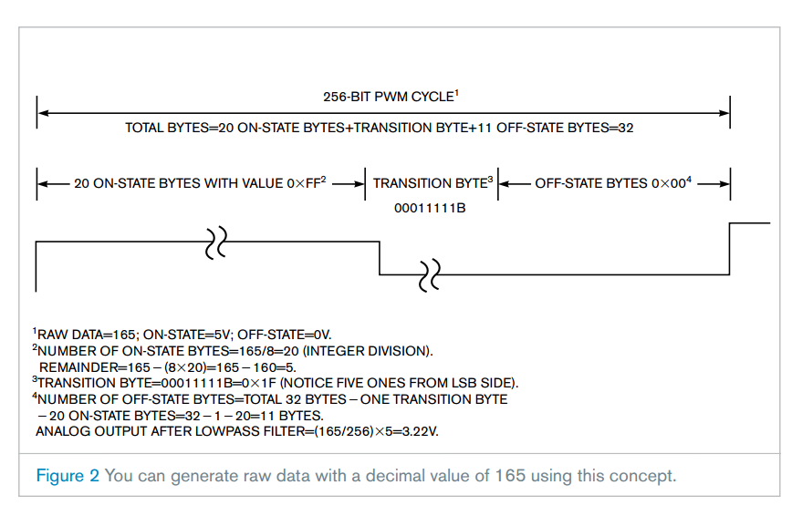
A PWM-conversion cycle consists of generating 256 bits—that is, 32 bytes. The number of “on” bits corresponds to the value of the raw data to convert into PWM. Hence, for 165 bits as the raw data, 165 bits are on and 91 bits are off. To generate a 165-bit on-period, the first 20 bytes—that is, 160 bits—transmit as 0×ff on-state bytes. The trick lies in judiciously composing the 21st, or transition, byte. This byte has some of its LSBs (least significant bits) as ones and the rest as zeros to form the required length of the on-period. In this case, the circuit needs five more on bits: 160+5=165. Hence, the transition byte should have a 00011111b pattern (byte=0×1f).
Figure 3 illustrates the process in flow-chart form.
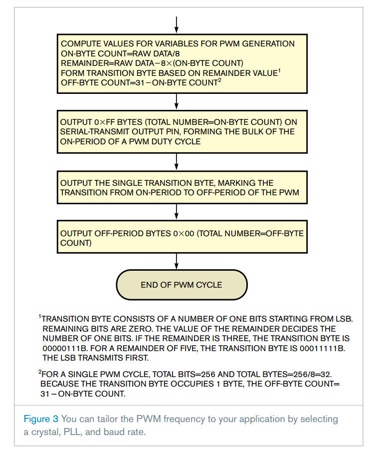
You can tailor the PWM frequency to your application by selecting a crystal, PLL (phase-locked loop), and baud rate. A simple RC filter can convert the PWM into a slow-moving analog value. Although this idea describes an 8-bit PWM, you can increase or decrease resolution by changing the total bits per PWM cycle. You correspondingly increase or decrease the conversion time.
Listing 1 provides a sample code for illustrating the concept. The code uses theMicrochip PIC18F4525, which has a 4-MHz crystal and 10-kHz baud rate for the synchronous serial communication, yielding 10,000/256=39.31 Hz of PWM frequency. You can filter it with a 0.1-sec RC filter, which is sufficient for slow-moving analog signals, such as speed setpoints for motion-control applications. By using a 20-MHz crystal, you can achieve synchronous serial baud rates greater than 1.5 MHz and PWM frequencies of a few kilohertz.
/*

This is a demo program from illustrating PWM generation using Synchronous Serial Port

Micro-controller for this code is 18F4525 Controller. however the code can be ported to any equivalent CPU

Date= 15/05/2009

Author: vishwas Vaidya

Version 1.00 contains the code for outputting a byte on synchronous serial transmitter

Variable Raw_Data is output to synchronous transmitter

Initialisations relevant for Synchronous Serial Communication

1.0 TRISC<6:7> = 1; PORT C FOR SERIAL COMMUNICATION.

2.0 SPEN = 1; .....RSCTA<7>

3.0 SPBRG = 0x64 ; For 4MHZ crystal Fosc/4x100 = 10 KHZ

4.0 TXSTA =0xBF  ; CSRC = 1; TX9 = 0;TXEN = 1;SYNC = 1; b3,b2 = x;TRMT = i/p;TX9D = x

5.0 RCSTA =0x80     ; SPEN = 1; all other bits beind Rx related reset to zero.

Initialisations for Transmit Interrupt

1.0 Bit PEIE ..(INTCON <6>) = 1 FOR ENABLING PERIPHERAL INTERRUPTS

2.0 Bit TXIE .. (PIE1 <4> ) = 1

3.0 Ensure that GIE is set

*/

//Project includes

//#include <pic18.h>

#include <p18f4525.h>

//Project defines

#define           tmr1_reload_L                 0x0A        //Timer 1 reload values for 1ms timing, therotical = 0xFBE7

#define           tmr1_reload_H                 0xFC        //fine tuned for RPM accuracy, practical = 0xFC0A

//Global variables

unsigned char timer_100ms;                      //system timer variables

unsigned char timer_500ms;

unsigned char timer_1000ms;

int timer_100ms_flag;                           //flag for 100ms timer

unsigned char Tx_Byte;                // Byte to be Transmitted in Tx interrupt

//------Variables for DAC house Keeping and Start conversion Start

unsigned char RawData; //Input digital data to be converted into analog

unsigned char Next_On_Byte_Count; // Number of 0xFF bytes in on duty period of PWM for next DAC cycle

unsigned char Next_Off_Byte_Count;// Number of 0x00 bytes to be transmitted in off state

unsigned char Next_Transition_Byte; // Last byte in On duty period beffore off duty starts(for Next DAC cycle)

unsigned char Remainder;  // Remainder of division of RawData by 32

//Look-up table for mapping remainder of RawData/32 for generation of "Transition byte"

//into number of '1's. e.g. remainder of 02 is mapped as 0x03 where number of ones are two.

const unsigned char Transition_Byte_Array [] =

{0X00,0x01, 0x03, 0x7, 0x0F, 0x1F, 0x3F, 0x7F};

unsigned char On_Byte_Count; // Number of 0xFF bytes in on duty period of PWM for current DAC cycle

unsigned char Transition_Byte; // Last byte in On duty period beffore off duty starts for current DAC cycle

//----Variables for DAC House Keeping end.

//--------Variables for Transmit_Byte start---

int On_Period_Flag ; //On Period is in Progress            ....... in 18f4525 defination as "bit" is not allow.

int Eoc_Flag ;//End of conversion flag

unsigned char DivisionData;//Debug division algorithm

unsigned char Off_Byte_Count; //Number of Off state bytes (0x00) during off period.

int Get_Next_Byte_Flag ;// Indicates that TxByte contents should be updated for next byte interval

//---------Variables for Transmit Byte end.

unsigned char New_RawData;

//Function definations

void controller_init (void)

{

      //Ports configuration

      TRISA = 0xFF;                    //PortA configured as input port

      TRISB = 0xFF;                       //PortB configured as input port

      TRISC = 0b11010010;                 //PortC configured for Serial Communication, RC2 as output pin for EGR output

      TRISD = 0b11110000;                 //PortD lower nibble configured as output

        TRISEbits.PSPMODE = ;            //Parallel slave port mode disabled for PortD digital I/O operation

//Debugging code for division

     DivisionData = 0x08;

    DivisionData = DivisionData * 0x15;

 //     DivisionData = 0xff/ DivisionData   ;     // Debug division algo

     //ADC module configuration

      ADCON0 = 0b00000001;                //ADC clock as Fosc/8 and CH0 selected

      ADCON1 = 0b00000000;            //PortA configured as analog input pin

      ADCON2 = 0b00000001;            //oscilator frequency focs/8

    PIE1bits.ADIE = ;            //Disable ADC interrupt

    //SPI module configuration

    PIE1bits.SSPIE = ;            //SPI interrupt disabled

    SSPSTAT = 0b00111111;               //SPI module configuration

    SSPCON1 = 0b00100001;                //

    //Timer 1 configuration for 1ms interrupt generation

    TMR1L = tmr1_reload_L;              //Load timer for next cycle

    TMR1H = tmr1_reload_H;

    T1CON = 0b00000001;                 //1:1 prescaler, internal clock source, enable timer

    // USART configuration for Synchronus Communication

    SPBRG = 0x64 ; //For 4MHZ crystal Fosc/4x100 = 10 KHZ

    TXSTA =0xBF  ; //CSRC = 1; TX9 = 0;TXEN = 1;SYNC = 1; b3,b2 = x;TRMT = i/p;TX9D = x

    RCSTA =0x80     ; //SPEN = 1; all other bits beind Rx related reset to zero.

    //Interrupts configuration

    INTCONbits.GIE = ;            //Global interrupt enable bit

    INTCONbits.PEIE = ;            //Peripheral interrupt enable bit

    PIE1bits.TMR1IE = ;                //enable timer 1 interrupt

    INTCONbits.INT0IE = ;            //Enable INT0 external interrupt

    INTCON2bits.INTEDG0 = ;            //INT interrupt configured for rising edge

    PIE1bits.TXIE = ;                 // Enable Transmit Interrupt

    INTCONbits.RBIF = ;                           //disable interrupt on portB pin change

    Tx_Byte    = 0x0F;                //Load Transmit Byte for first interrupt

}

//void interrupt isr (void)

void isr (void)

{

      //Timer 1 used to generate 1ms periodic interrupt.

      if (PIR1bits.TMR1IF)

      {

            PIR1bits.TMR1IF = ;                   //clear interrupt flag

            TMR1L = tmr1_reload_L;        //Reload timer for next cycle

            TMR1H = tmr1_reload_H;

            if ( timer_100ms ==  )

            {

                  timer_100ms = ;        //reset 100ms_timer if 100msecs elapsed

                  timer_100ms_flag = ;   //set timer flag

            }

            else

                  timer_100ms++;          //else increment 100ms_timer

      }

    if ( PIR1bits.TXIF)

    {// Load transmit register with the byte to be transmitted

        TXREG = Tx_Byte    ;

        Get_Next_Byte_Flag = ; //Get next value of Tx_byte

    }

}

void system_init (void)

{

      timer_100ms = ;                    //initialise system timers

      timer_500ms = ;

      timer_1000ms = ;

      On_Period_Flag =;        //Initial period in PWM is on state

      Eoc_Flag =;                    // Assume conversion is over at the start

      Tx_Byte    = 0x3F    ;         // First byte is mostly all bits on

      Get_Next_Byte_Flag =;

}

void system_timers_update (void)

{

      timer_500ms++;                      //increment timer

      if (timer_500ms == )               //reset timer every 0.5 second

            timer_500ms = ;

      timer_1000ms++;                     //increment timer

      if (timer_1000ms == )             //reset timer every 1 second

            timer_1000ms = ;

}

//Function for DAC House Keeping

/* This routine takes RawData as input from the calling routine and works out PWM

on duty cycle period for the same. This period is specified as number of 0xFF bytes

(NextOnByteCount) followed by last byte (known as NextTransitionByte) to complete

the own "duty-cycle period". For example for Rawdata = 0x86 = 134 decimal

We should have 134 bits on and 122 bits off in 256 bit interval. To generate

134 bit on interval we can generate 16 bytes with value 0xff to give 128 bit on time giving

NextOnByteCount = 0x28 (40 Decimal). To complete remaining 6 bit interval out of 134 bit on time we should ouput

0x00111111b = 0x3F which gives first 6 bits as "1". Remember that shifting sequence is from lsb to msb.

*/

void DAC_House_Keeping (void)

{

    Next_On_Byte_Count = RawData >>  ;     //RawDat/8 = number of on bytes with 0xff value

    Remainder = RawData - (Next_On_Byte_Count << ) ;    //Remainder indicates last byte in on period

    Next_Transition_Byte = Transition_Byte_Array[Remainder];    //Map remainder into on bits.

    Next_Off_Byte_Count =  - Next_On_Byte_Count ;        //OffByte +OnByte +TransitionByte = 32

}

//Function for Start of conversion

/*This routine is invoked when End_Of_Conversion is true(Eocflag) and new RawData is available for

conversion. The new Raw data is processed by the DAC_House_Keeping routine to generate

OnByteCount and TransitionByte for next cycle. These values are updated at the start of

every new conversion cycle. EocFlag is rest to mark "conversion in progress" condition

*/

void Start_DA_Conversion (void)

    {    On_Period_Flag = ; //Initial perid of of PWM is on state

        Tx_Byte = 0xff ;//First Byte will be 0x ff in most cases.

        On_Byte_Count = Next_On_Byte_Count; // Set number of 0xff bytes during on duty

        Off_Byte_Count = Next_Off_Byte_Count;//Set number of 0x00 bytes

        Transition_Byte = Next_Transition_Byte; //Set the last byte at the transition from on to off

        Eoc_Flag =  ; // Conversion is in progress now.

    }

//-----------------Comments for Transmit_Next_Byte Start---------------------------------------------

// Function for Byte Transmition on synchronous communication channel

/* This routine actually implements PWM on serial synchronous channel. It is invoked

every time the transmit interrupt submits a byte to the synchronous transmitter.

Get_Next_Byte_Flag triggers this routine

The PWM cycle is logically divided into three segments, viz: On duty, transition and off duty.

The byte to be transmitted (TxByte)takes on three possible values depending on which segement

of the PWM cycle is currently in progress:

1.0 If on duty is in progress then TxByte = 0x ff

(THIS CONDITION is defined when OnBytecount >0 and On_Period_flag is set)

2.0 If "on to off" transition is in progress then TxByte = Transition_Byte

(This condition is defined when Onbyte count = 0 and On_Period_flag is set. Once

this condition is detected, transition byte is submitted for transmission and

On_Period_flag is reset. )

3.0 If off duty is in progress then TxByte = 0x00

*/

//--------------------------------Code for Transmit_Next_Byte Start----------------

void Transmit_Next_Byte (void)

{

    Get_Next_Byte_Flag = ;//Reset the flag set by Transmit ISR

    if (On_Period_Flag)

    { // Onduty is in progress

        if (On_Byte_Count > )

        {

            On_Byte_Count --;

        }

        else

        {        //On_Byte_count = 0 implies no more 0x ff to be transmitted

            if (!(Tx_Byte == Transition_Byte))

            {

                Tx_Byte = Transition_Byte;

            }

            // Transmit Transition_Byte    if not already transmitted.

            //However if Transition_Byte is transmitted last time

            // then start off duty cycle

            else

            {

                Tx_Byte = 0x00; // off state byte

                On_Period_Flag = ;//On period ends

                Off_Byte_Count--;// Start tracking off_bytes transmitted

            }

        }

    }

    else

    {

        if (Off_Byte_Count > )

        {

            Off_Byte_Count --;

        }

        else

        {

            Eoc_Flag =;

        } //If off_bytes have been all transmitted,

    }

}                   //end the conversion cycle.

//Main program

// this program illustrates how the "Software DAC chip" formed by sync. serial port can be used to convert digital raw-data

// into PWM/analog voltage. Actual application can be built by expanding this concept.

void main (void)

{

      controller_init ();                 //initialise controller

      system_init ();                     //initialise global variables, timers & counters

      New_RawData = 0xA5;

      DivisionData = 0x05;

      DivisionData = 0x01/ DivisionData   ;     // Debug division algo

      while ()

      {     New_RawData = 0xA5;        //RawData = 165 Say. 5 On Bytes, TransitionByte=0x1f,Off Bytes=2. Actual application can contain code for generating the raw data corrosponding to the application.

            system_timers_update ();      //system timer function

        if (timer_100ms_flag) { timer_100ms_flag = ;

                  RawData = New_RawData;        //update Raw Data

                  DAC_House_Keeping ();         //Prepare for next conversion cycle

                        }

    // Keep converting the RawData from digital to analog

    if (Eoc_Flag) Start_DA_Conversion ();//Start at EOC rising edge converting

    if (Get_Next_Byte_Flag) Transmit_Next_Byte();//Keep transmitting on serial line

      }

}
Unused port adds a PWM/analog channel to a microcontroller的更多相关文章
- How to do SSH Tunneling (Port Forwarding)
How to do SSH Tunneling (Port Forwarding) In this post we will see how ssh works?, what is SSH tunne ...
- PWM DAC vs. Standalone
http://analogtalk.com/?p=534 http://analogtalk.com/?p=551 Posted by AnalogAdvocate on April 09, 2010 ...
- M451 PWM对照数据手册分析
PWM_T Struct Reference Control Register » Pulse Width Modulation Controller(PWM) typedef struct { ...
- 说说M451例程之PWM的寄存器讲解
M451提供了两路PWM发生器.每路PWM支持6通道PWM输出或输入捕捉.有一个12位的预分频器把时钟源分频后输入给16位的计数器,另外还有一个16位的比较器.PWM计数器支持向上,向下,上下计数方式 ...
- 图解再谈ssh port forwarding-ssh隧道技术
https://www.ramkitech.com/2012/04/how-to-do-ssh-tunneling-port-forwarding.html https://www.cnblogs.c ...
- 【DM642学习笔记六】TI参考文档--DM642 Video Port Mini Driver
这个文档介绍了在DM642EVM板上视频采集和显示微驱动的使用和设计.用EDMA进行存储器和视频端口的数据传输.为了增强代码的复用性和简化设计过程,驱动分为通用视频端口层和特定编解码芯片微驱动层两个 ...
- Keil MDK STM32系列(七) STM32F4基于HAL的PWM和定时器
Keil MDK STM32系列 Keil MDK STM32系列(一) 基于标准外设库SPL的STM32F103开发 Keil MDK STM32系列(二) 基于标准外设库SPL的STM32F401 ...
- Keil MDK STM32系列(八) STM32F4基于HAL的PWM和定时器输出音频
Keil MDK STM32系列 Keil MDK STM32系列(一) 基于标准外设库SPL的STM32F103开发 Keil MDK STM32系列(二) 基于标准外设库SPL的STM32F401 ...
- Serial Port Programming on Linux(转载)
This is a tutorial on how to program the Serial Ports on your Linux box.Serial Ports are nice little ...
随机推荐
- sicily 1003. Hit or Miss
Description One very simple type of solitaire game known as "Hit or Miss" (also known as & ...
- 虚拟机NAT网络设置
1. 虚拟机设置 2. 本地网络设置 3. 本地虚拟网卡设置 4. 安装虚拟机,设置网络为NAT方式即可访问外网.
- 防范XSS跨站
所有jsp页面输出全部使用<c:out value="{}"/> 默认就是escapeXml="true" java中间件,<c:out /& ...
- Django之Cookie、Session和自定义分页
cookie Cookie的由来 大家都知道HTTP协议是无状态的. 无状态的意思是每次请求都是独立的,它的执行情况和结果与前面的请求和之后的请求都无直接关系,它不会受前面的请求响应情况直接影响,也不 ...
- 爬虫基础库之beautifulsoup的简单使用
beautifulsoup的简单使用 简单来说,Beautiful Soup是python的一个库,最主要的功能是从网页抓取数据.官方解释如下: ''' Beautiful Soup提供一些简单的.p ...
- beego与websocker的集成
上周刚好遇到这个问题. 周末在家里按网上的方案测试了一下. 希望下周进展顺利~~ URL: http://blog.csdn.net/u012210379/article/details/729120 ...
- mysql 5.7 表名大小写不敏感
修改 my.cnf 添加 [mysqld] lower_case_table_names=1 重启MySQL service mysqld restart
- iis应用池内存溢出卡死优化
1.修改回收阀值memoryLimit 在ASP.NET Web服务器上,ASP.NET所能够用到的内存,通常不会等同于所有的内存数量.在machine.config(C:/WINDOWS/Micro ...
- lr中用strtok函数分割字符串
需要在loadrunner里面获得“15”(下面红色高亮的部分),并做成关联参数. ,6,5,0,4,0,3,0,3,2,0,0,0,1 用web_reg_save_param取出“8,7,5,15, ...
- Ubuntu 如何更换阿里源
#进入源地址 cd /etc/apt #备份源文件 sudo cp sources.list sources.list.bak #编辑 sudo vim /etc/apt/sources.list d ...