总线SPI的Arduino库函数
来源参考:https://www.cnblogs.com/MyAutomation/p/9348480.html
总线SPI的Arduino库函数
SPI基本知识
SPI:高速同步串行口。是一种标准的四线同步双向串行总线。
SPI,是英语Serial Peripheral interface的缩写,顾名思义就是串行外围设备接口。是Motorola首先在其MC68HCXX系列处理器上定义的。SPI接口主要应用在 EEPROM,FLASH,实时时钟,AD转换器,还有数字信号处理器和数字信号解码器之间。SPI,是一种高速的,全双工,同步的通信总线,并且在芯片的管脚上只占用四根线,节约了芯片的管脚,同时为PCB的布局上节省空间,提供方便,正是出于这种简单易用的特性,如今越来越多的芯片集成了这种通信协议,比如AT91RM9200。
SPI总线系统是一种同步串行外设接口,它可以使MCU与各种外围设备以串行方式进行通信以交换信息。外围设置FLASHRAM、网络控制器、LCD显示驱动器、A/D转换器和MCU等。SPI总线系统可直接与各个厂家生产的多种标准外围器件直接接口,该接口一般使用4条线:串行时钟线(SCLK)、主机输入/从机输出数据线MISO、主机输出/从机输入数据线MOSI和低电平有效的从机选择线SS(有的SPI接口芯片带有中断信号线INT、有的SPI接口芯片没有主机输出/从机输入数据线MOSI)。
SPI的通信原理很简单,它以主从方式工作,这种模式通常有一个主设备和一个或多个从设备,需要至少4根线,事实上3根也可以(用于单向传输时,也就是半双工方式)。也是所有基于SPI的设备共有的,它们是SDI(数据输入)、SDO(数据输出)、SCLK(时钟)、CS(片选)。
MOSI–SPI总线主机输出/ 从机输入(SPI Bus Master Output/Slave Input);
MISO–SPI总线主机输入/ 从机输出(SPI Bus Master Input/Slave Output);
SCLK–时钟信号,由主设备产生;
CS–从设备使能信号,由主设备控制(Chip select),有的IC此pin脚叫SS。
其中CS是控制芯片是否被选中的,也就是说只有片选信号为预先规定的使能信号时(高电位或低电位),对此芯片的操作才有效。这就允许在同一总线上连接多个SPI设备成为可能。
3根线MOSI,MISO,SCLK负责通讯。通讯是通过数据交换完成的,SPI是串行通讯协议,也就是说数据是一位一位的传输的。由SCK提供时钟脉冲,SDI,SDO则基于此脉冲完成数据传输,这就是SCLK时钟线存在的原因。数据输出通过 SDO线,数据在时钟上升沿或下降沿时改变,在紧接着的下降沿或上升沿被读取。完成一位数据传输,输入也使用同样原理。这样,在至少8次时钟信号的改变(上沿和下沿为1次),就可以完成8位数据的传输。
在点对点的通信中,SPI接口不需要进行寻址操作,且为全双工通信,简单高效。在多个从设备的系统中,每个从设备需要独立的使能信号,硬件上比I2C要稍微复杂。


SPI通信有4种不同的模式,不同的从设备可能在出厂时就配置为某种模式,这是不能改变的;但通信双方必须是工作在同一模式下,所以需要对主设备的SPI模式进行配置。通过CPOL(时钟极性)和CPHA(时钟相位)来设置主设备的通信模式,具体如下: Mode0:CPOL=0,CPHA=0 Mode1:CPOL=0,CPHA=1 Mode2:CPOL=1,CPHA=0 Mode3:CPOL=1,CPHA=1
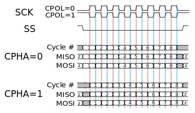
时钟极性CPOL用来配置SCLK的电平处于哪种状态时是空闲态或者有效态,时钟相位CPHA用来配置数据采样是在第几个SCLK脉冲边沿: CPOL=0,表示当SCLK=0时处于空闲态,所以有效状态就是SCLK处于高电平时 CPOL=1,表示当SCLK=1时处于空闲态,所以有效状态就是SCLK处于低电平时 CPHA=0,表示数据采样是在第1个边沿,数据发送在第2个边沿 CPHA=1,表示数据采样是在第2个边沿,数据发送在第1个边沿
例如: CPOL=0,CPHA=0:此时空闲态时,SCLK处于低电平,数据采样是在第1个边沿,也就是SCLK由低电平到高电平的跳变,所以数据采样是在上升沿,数据发送是在下降沿。
CPOL=0,CPHA=1:此时空闲态时,SCLK处于低电平,数据发送是在第1个边沿,也就是SCLK由低电平到高电平的跳变,所以数据采样是在下降沿,数据发送是在上升沿。
CPOL=1,CPHA=0:此时空闲态时,SCLK处于高电平,数据采集是在第1个边沿,也就是SCLK由高电平到低电平的跳变,所以数据采集是在下降沿,数据发送是在上升沿。
CPOL=1,CPHA=1:此时空闲态时,SCLK处于高电平,数据发送是在第1个边沿,也就是SCLK由高电平到低电平的跳变,所以数据采集是在上升沿,数据发送是在下降沿。
SPI库函数
SPISettings 配置SPI总线端口
Description 描述
The SPISettings object is used to configure the SPI port for your SPI device. All 3 parameters are combined to a single SPISettings object, which is given to SPI.beginTransaction().
When all of your settings are constants, SPISettings should be used directly in SPI.beginTransaction(). See the syntax section below. For constants, this syntax results in smaller and faster code.
If any of your settings are variables, you may create a SPISettings object to hold the 3 settings. Then you can give the object name to SPI.beginTransaction(). Creating a named SPISettings object may be more efficient when your settings are not constants, especially if the maximum speed is a variable computed or configured, rather than a number you type directly into your sketch.
Syntax 语法
SPI.beginTransaction(SPISettings(14000000, MSBFIRST, SPI_MODE0)) Note:Best if all 3 settings are constants
SPISettings mySettting(speedMaximum, dataOrder, dataMode) Note:Best when any setting is a variable''
Parameters 参数
speedMaximum: The maximum speed of communication. For a SPI chip rated up to 20 MHz, use 20000000.
dataOrder: MSBFIRST or LSBFIRST
dataMode : SPI_MODE0, SPI_MODE1, SPI_MODE2, or SPI_MODE3 四种数据传送模式
Returns None 返回
begin() 初始化SPI总线的参数
Description
Initializes the SPI bus by setting SCK, MOSI, and SS to outputs, pulling SCK and MOSI low, and SS high.
Syntax SPI.begin()
Parameters None
Returns None
end() 关闭SPI总线
Description
Disables the SPI bus (leaving pin modes unchanged).
Syntax SPI.end()
Parameters None
Returns None
beginTransaction() 开始使用SPI总线
Description
Initializes the SPI bus using the defined SPISettings.
Syntax
SPI.beginTransaction(mySettings);
Parameters
mySettings: the chosen settings according to SPISettings.
Returns None.
endTransaction() 停用SPI总线
Description
Stop using the SPI bus. Normally this is called after de-asserting the chip select, to allow other libraries to use the SPI bus.
Syntax
SPI.endTransaction()
Parameters None.
Returns None.
setBitOrder() 设置传输数据时的先后顺序
Description
This function should not be used in new projects. Use SPISettings with SPI.beginTransaction() to configure SPI parameters.
Sets the order of the bits shifted out of and into the SPI bus, either LSBFIRST (least-significant bit first) or MSBFIRST (most-significant bit first).
Syntax
SPI.setBitOrder(order)
Parameters
order: either LSBFIRST or MSBFIRST
Returns None
setClockDivider() 设置时钟分频器
Description
This function should not be used in new projects. Use SPISettings with SPI.beginTransaction() to configure SPI parameters.
Sets the SPI clock divider relative to the system clock. On AVR based boards, the dividers available are 2, 4, 8, 16, 32, 64 or 128. The default setting is SPI_CLOCK_DIV4, which sets the SPI clock to one-quarter the frequency of the system clock (4 Mhz for the boards at 16 MHz).
Arduino DueOn the Due, the system clock can be divided by values from 1 to 255. The default value is 21, which sets the clock to 4 MHz like other Arduino boards.
Syntax
SPI.setClockDivider(divider)
Parameters

Returns None
setDataMode() 设置数据模式,即时钟的极性和相位
Description
This function should not be used in new projects. Use SPISettings with SPI.beginTransaction() to configure SPI parameters.
Sets the SPI data mode: that is, clock polarity and phase. See the Wikipedia article on SPI for details.
Syntax
SPI.setDataMode(mode)
Parameters

Returns None
transfer(), transfer16() 数据传送
Description
SPI transfer is based on a simultaneous send and receive: the received data is returned in receivedVal (or receivedVal16). In case of buffer transfers the received data is stored in the buffer in-place (the old data is replaced with the data received).
Syntax
receivedVal = SPI.transfer(val) receivedVal16 = SPI.transfer16(val16) SPI.transfer(buffer, size)
Parameters
val: the byte to send out over the bus val16: the two bytes variable to send out over the bus buffer: the array of data to be transferred
Returns the received data
usingInterrupt() 在中断中做SPI处理
Description
If your program will perform SPI transactions within an interrupt, call this function to register the interrupt number or name with the SPI library. This allows SPI.beginTransaction() to prevent usage conflicts. Note that the interrupt specified in the call to usingInterrupt() will be disabled on a call to beginTransaction() and re-enabled in endTransaction().
Syntax
SPI.usingInterrupt(interruptNumber)
Parameters
interruptNumber: the associated interrupt number.
Returns None.
总线SPI的Arduino库函数的更多相关文章
- OneWire总线的Arduino库函数
OneWire总线基本点 One-wire总线是DALLAS公司研制开发的一种协议,采用单根信号线,既传输时钟,又传输数据而且数据传输是双向的.它具有节省I/O 口线资源.结构简单.成本低廉.便于总线 ...
- I2C总线的Arduino库函数
I2C总线的Arduino库函数 I2C即Inter-Integrated Circuit串行总线的缩写,是PHILIPS公司推出的芯片间串行传输总线.它以1根串行数据线(SDA)和1根串行时钟线(S ...
- Arduino库函数中文说明
#define 常量名 常量值 % 取模运算符 String abc / char abc[n] 定义字符串 pinMode(pin,mode); 用于引脚的初始化 mode包括 INPUT ...
- arduino库函数1
https://wenku.baidu.com/view/e657b1f0bcd126fff6050baf.html 的阅读笔记.现在到了 第四十页. setup应该是 在开始 执行一次. 然后 lo ...
- 步进电机的Arduino库函数
This library allows you to control unipolar or bipolar stepper motors. To use it you will need a ste ...
- 伺服电机的Arduino库函数
servo.attach(pin) //连接伺服电机的信号线于控制板的引脚,9或10号引脚servo.attach(pin, min, max) servo: a variable of type ...
- SPI、I2C、UART三种串行总线协议的区别
第一个区别当然是名字: SPI(Serial Peripheral Interface:串行外设接口); I2C(INTER IC BUS) UART(Universal Asynchronous R ...
- SPI、I2C、UART三种串行总线协议的区别和SPI接口介绍(转)
SPI.I2C.UART三种串行总线协议的区别 第一个区别当然是名字: SPI(Serial Peripheral Interface:串行外设接口); I2C(INTER IC BUS) UART( ...
- SPI总线介绍
1. 简介 SPI, Serial Peripheral Interface, 串行外设接口, 是一种高速的.全双工.同步的通信总线SPI在芯片的管脚上只占用四根线 SPI接口主要用于MCU与各种外围 ...
随机推荐
- Jigsaw pre-training:摆脱ImageNet,拼图式主干网络预训练方法 | ECCV 2020
Jigsaw pre-training以拼图的方式从检测数据集中生成用于主干网络预训练的数据集,而不需要额外的预训练数据集,如ImageNet.另外为了让网络更好的适应拼图数据,论文提出ERF-ada ...
- Unity中利用柏林噪声(perlinnoise)制作摇摆效果
perlinnoise是unity中Mathf下的一个函数,需要两个float参数x和y进行采样,返回一个0-1的float型. 项目里经常要随机摇摆某些东西,比如摄像机,某个随机运动的目标等等,都可 ...
- 【平台开发】— 4.mysql建库建表
本想着把前端脚手架run起来了,然后就可以借着登录来捋一下前后端交互的过程.但是后端导入JPA的时候就发现了,还没有数据库. 既然是本着学习的目的,那咱也不想只在后端写死返回的数据,要做就做全套. 一 ...
- SpringMVC-08-整合SSM之基本环境搭建
8. 整合SSM 环境要求 IDEA MySQL 5.5 Tomcat 9 Maven 3.5.2 要求: 需要熟练掌握MySQL数据库,Spring,JavaWeb及Mybatis知识,简单的前端知 ...
- C001:打印勾
程序: #include "stdafx.h" int _tmain(int argc, _TCHAR* argv[]) { printf(" *\n"); p ...
- 用于测试 SqlAnalyzer1.01 的21个测试用例
感慨:当年看着 https://www.cnblogs.com/heyang78/p/11451814.html 一文望洋兴叹,如今我也自己做出来了! 21. 原文=select name, cnt ...
- MySQL教程 | 菜鸟教程
装数据库失败后的重装步骤!!! --[创建数据库]CREATE DATABASE <数据库名>: --使用mysqladamin 创建数据库-- 使用普通用户,你可能需要特定的权限来创建或 ...
- 面试:为了进阿里,重新翻阅了Volatile与Synchronized
该系列文章收录在公众号[Ccww技术博客],原创技术文章早于博客推出 在深入理解使用Volatile与Synchronized时,应该先理解明白Java内存模型 (Java Memory Model, ...
- liunx之firewalld&SELinux
1.firewalld的基本使用 启动: systemctl start firewalld 关闭: systemctl stop firewalld 查看状态: systemctl status f ...
- 你想了解的分布式文件系统HDFS,看这一篇就够了
1.分布式文件系统 计算机集群结构 分布式文件系统把文件分布存储到多个节点(计算机)上,成千上万的计算机节点构成计算机集群. 分布式文件系统使用的计算机集群,其配置都是由普通硬件构成的,与用多个处理器 ...