Project 03- STM32F4xx PID controller
Project 03- STM32F4xx PID controller
CMSIS files from ARM provides ARM Math functions.
There are also PID controller functions in different formats for f32, q31 and q7.
This tutorial/project will talk about how to implement PID controller on STM32F4xx using PID functions from ARM.
PID Controller
Fast about PID controller.
PID stands for Proportional-Integral-Derivative controller.
This is a control loop feedback mechanism widely used in industrial control systems.
It calculates the error between measured value and the desired setpoint value.
According to the error, it then calculates output value to minimize this error.
I will not go step-by-step on how PID works. More you can look on the sites below:
ARM PID library
ARM company provides 3 different PID controller functions:
- f32: float
- q31: integer
- q7: char
For each of the three types, you have three functions:
- f32
- arm_pid_init_f32
- arm_pid_reset_f32
- arm_pid_f32
- q31
- arm_pid_init_q31
- arm_pid_reset_q31
- arm_pid_q31
- q7
- arm_pid_init_q7
- arm_pid_reset_q7
- arm_pid_q7
There are also ARM PID structure, where you pass PID parameters.
More in project example below.
If you need additional info about these functions, you have detailed manual here.
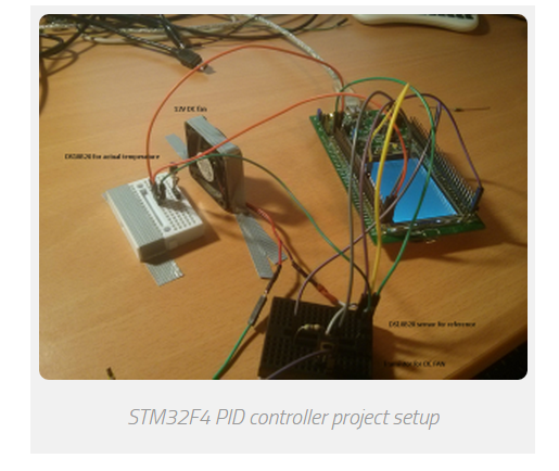
PID Sample project
In the project, 2 DS18B20 temperature sensors are used.
They are configured in 12bit resolution, so delay between 2 calculations is about ~750ms.
If you read about PID controller, you realize that you cannot calculate PID controller results every x microcontroller,
because it has integral part which is used to sum all the errors in period.
More calculations you have, more integral error you have.
We have one device connected as “reference” temperature.
Second sensor is placed near DC FAN,
so when DC fan is turned ON, it is cooling the second DS18B20.
The goal is, that both temperatures are the same.
In my case, it was about 23°C on the reference sensor.
Then, I touched the second DS18B20 near DC fan and I heated them. DC fan was turned on.
Everything is displayed via USART to computer.
FAN is controlled via 1kHz PWM output.
According to the error between both sensors, more error, more duty cycle to DC fan.
This is just a sample project, so PID parameters are not set optimal.
For every project you have to set parameters for specific project.
This example successfully works on all STM32F4xx development board such as Discovery and Nucleo.
In the example, 1 PID controller is used.
If you need to control more than just one thing,
you can add additional ARM PID instances and
you can use more than just one PID controller at a time.
Pinout
- Both DS18B20 sensors are connected to the same pin: PA6
- DC fan PWM pin (controlled via transistor): PA5
- USART output: PB6, 115200baud
Example
/**

 *    Keil project for DS18B20 & ARM PID example

 *

 *    Before you start, select your target, on the right of the "Load" button

 *

 *    @author        Tilen Majerle

 *    @email        tilen@majerle.eu

 *    @website    http://stm32f4-discovery.com

 *    @ide        Keil uVision 5

 *    @packs        STM32F4xx Keil packs version 2.2.0 or greater required

 *    @stdperiph    STM32F4xx Standard peripheral drivers version 1.4.0 or greater required

 *

 *    Additional defines in "Options for Target" > "C/C++" > "Defines"

 *        - ARM_MATH_CM4

 *        - __FPU_PRESENT = 1

 */

/* Include core modules */

#include "stm32f4xx.h"

/* Include my libraries here */

#include "defines.h"

#include "tm_stm32f4_delay.h"

#include "tm_stm32f4_onewire.h"

#include "tm_stm32f4_ds18b20.h"

#include "tm_stm32f4_disco.h"

#include "tm_stm32f4_usart.h"

#include "tm_stm32f4_pwm.h"

#include <stdio.h>

/* Include ARM math */

#include "arm_math.h"

/* How many sensors we are expecting on 1wire bus? */

#define EXPECTING_SENSORS    2

#define TEMP_CURRENT        temps[1]    /* Temperature we actually have */

#define TEMP_WANT            temps[0]    /* Temperature we want to have */

/* Choose PID parameters */

#define PID_PARAM_KP        100            /* Proporcional */

#define PID_PARAM_KI        0.025        /* Integral */

#define PID_PARAM_KD        20            /* Derivative */

int main(void) {

    /* Timer data for PWM */

    TM_PWM_TIM_t TIM_Data;

    char buf[];

    uint8_t devices, i, count;

    /* DS18B20 devices ID */

    uint8_t device[EXPECTING_SENSORS][];

    /* Temperatures from 2 sensors */

    float temps[EXPECTING_SENSORS];

    /* PID error */

    float pid_error;

    /* Duty cycle for PWM */

    float duty = ;

    /* ARM PID Instance, float_32 format */

    arm_pid_instance_f32 PID;

    /* One wire instance */

    TM_OneWire_t OneWire;

    /* Set PID parameters */

    /* Set this for your needs */

    PID.Kp = PID_PARAM_KP;        /* Proporcional */

    PID.Ki = PID_PARAM_KI;        /* Integral */

    PID.Kd = PID_PARAM_KD;        /* Derivative */

    /* Initialize PID system, float32_t format */

    arm_pid_init_f32(&PID, );

    /* Initialize system */

    SystemInit();

    /* Initialize delay */

    TM_DELAY_Init();

    /* Initialize Leds */

    TM_DISCO_LedInit();

    /* Initialize USART1, TX: PB6, 115200 baud */

    TM_USART_Init(USART1, TM_USART_PinsPack_2, );

    /* Initialize TIM2, 1kHz frequency */

    TM_PWM_InitTimer(TIM2, &TIM_Data, );

    /* Initialize TIM2, Channel 1, PinsPack 2 = PA5 */

    TM_PWM_InitChannel(&TIM_Data, TM_PWM_Channel_1, TM_PWM_PinsPack_2);

    /* Set default duty cycle */

    TM_PWM_SetChannelPercent(&TIM_Data, TM_PWM_Channel_1, duty);

    /* Initialize OneWire, pin PA6 */

    TM_OneWire_Init(&OneWire, GPIOA, GPIO_PIN_6);

    /* Checks for any device on 1-wire */

    count = ;

    devices = TM_OneWire_First(&OneWire);

    while (devices) {

        /* Get full ROM value, 8 bytes, give location of first byte where to save */

        TM_OneWire_GetFullROM(&OneWire, device[count]);

        /* Increase count for devices */

        count++;

        /* Get next device */

        devices = TM_OneWire_Next(&OneWire);

    }

    /* We need 2 devices */

    if (count != ) {

        TM_USART_Puts(USART1, "We expect 2 devices on 1-wire. Quiting!\n");

        /* While */

        while ();

    }

    /* Go through all connected devices and set resolution to 12bits */

    for (i = ; i < count; i++) {

        TM_DS18B20_SetResolution(&OneWire, &device[i][], TM_DS18B20_Resolution_12bits);

    }

    /* Start temperature conversion on all devices */

    TM_DS18B20_StartAll(&OneWire);

    while () {

        /* If all sensors are done with conversion */

        /* This will happen about every 750ms, because DS18B20 needs ~750ms for conversion in 12bit resolution mode */

        if (TM_DS18B20_AllDone(&OneWire)) {

            /* Read temperature 1, reference temperature */

            TM_DS18B20_Read(&OneWire, device[], &TEMP_WANT);

            /* Read temperature 2, actual temperature */

            TM_DS18B20_Read(&OneWire, device[], &TEMP_CURRENT);

            /* Start new temperature conversion on all devices */

            TM_DS18B20_StartAll(&OneWire);

            /* Set LEDs according to the which temperature is higher */

            if (TEMP_CURRENT > TEMP_WANT) {

                TM_DISCO_LedOn(LED_GREEN);

                TM_DISCO_LedOff(LED_RED);

            } else if (TEMP_CURRENT < TEMP_WANT) {

                TM_DISCO_LedOn(LED_RED);

                TM_DISCO_LedOff(LED_GREEN);

            } else {

                TM_DISCO_LedOff(LED_ALL);

            }

            /* Calculate error */

            pid_error = TEMP_CURRENT - TEMP_WANT;

            /* Calculate PID here, argument is error */

            /* Output data will be returned, we will use it as duty cycle parameter */

            duty = arm_pid_f32(&PID, pid_error);

            /* Check overflow, duty cycle in percent */

            if (duty > ) {

                duty = ;

            } else if (duty < ) {

                duty = ;

            }

            /* Set PWM duty cycle for DC FAN to cool down sensor for "TEMP_CURRENT" */

            TM_PWM_SetChannelPercent(&TIM_Data, TM_PWM_Channel_1, duty);

            /* Format string */

            sprintf(buf, "Expected:   %2.3f C\nActual:     %2.3f C\nError:      %2.3f C\nDuty cycle: %3.2f %%\n----\n", TEMP_WANT, TEMP_CURRENT, pid_error, duty);

            /* Send to USART */

            TM_USART_Puts(USART1, buf);

        }

    }

}
2 PID controller
2.1 Description
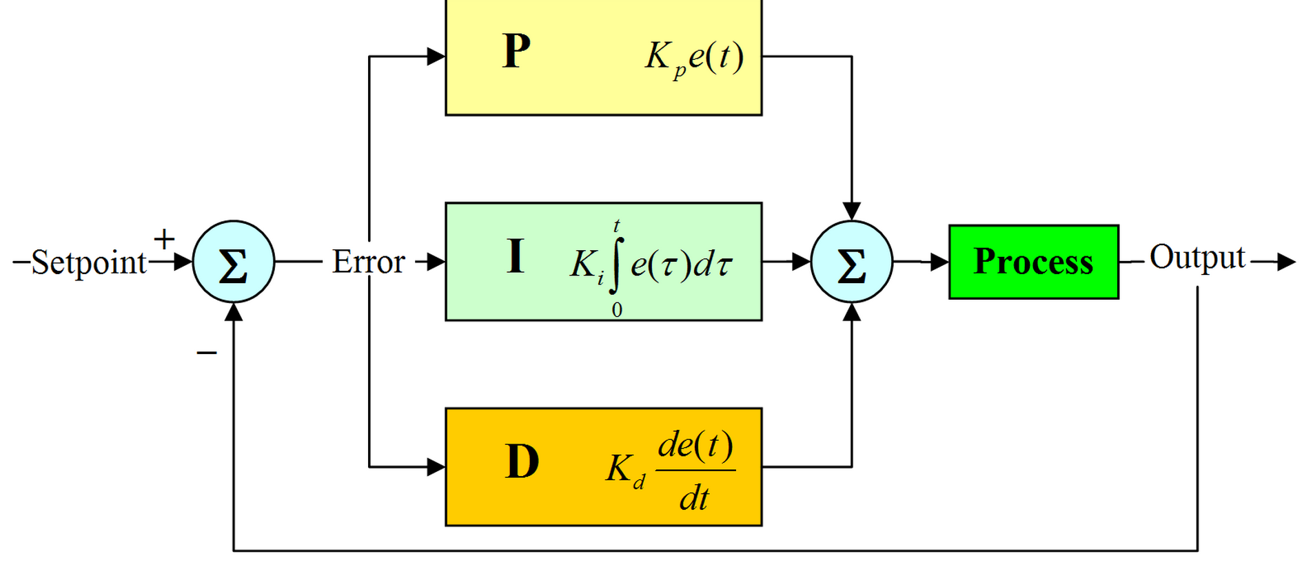
The proportional-integral-derivative or PID controller is commonly used in the industry.
It is a feedback loop controller that manages the process command with a view to reducing the error
between the desired set point and the measured process variable.
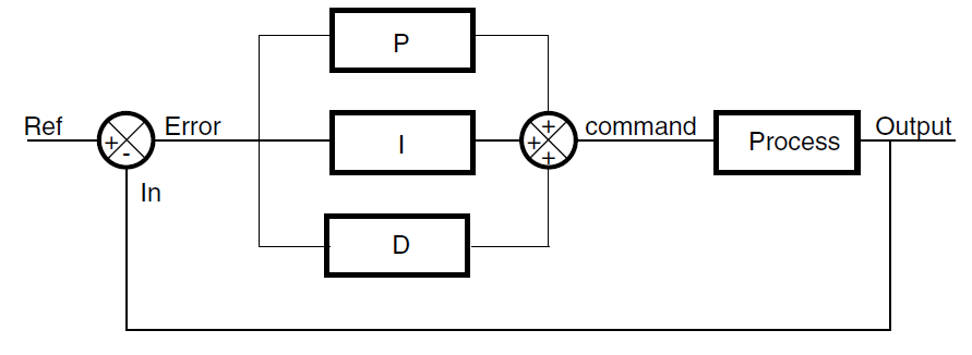
The following block diagram shows the parallel structure of a PID controller.
This is the structure implemented in this DSP library.
Figure 1. Block diagram of PID controller
DSP library functions
The DSP library provides three PID functions:
● DoPID: a PID core loop coded in C (the error is computed outside the function)
● DoFullPID: a full PID controller coded in C (with error computing)
● PID_stm32: an optimized PID core loop written in assembly
Project 03- STM32F4xx PID controller的更多相关文章
- SpringMVC学习03(控制器Controller)
3.控制器Controller 3.1 控制器Controller 控制器复杂提供访问应用程序的行为,通常通过接口定义或注解定义两种方法实现. 控制器负责解析用户的请求并将其转换为一个模型. 在Spr ...
- 《Symfony 5全面开发》教程03、使用Controller创建第一个页面
我们使用Phpstorm打开我们的项目目录,展开项目目录文件夹. Symfony项目其实也是composer项目,如果你新拿到一个Symfony项目, 你可以在控制台中使用composer insta ...
- PID控制器(比例-积分-微分控制器)- II
Table of Contents Practical Process Control Proven Methods and Best Practices for Automatic PID Cont ...
- Be a Smart Project Manager
The key to being a smart project manager is to remember how you are going to manage your project, to ...
- 增量与位置PID
转载:http://blog.sina.com.cn/s/blog_408540af0100b17n.html http://bbs.ednchina.com/BLOG_ARTICLE_211739. ...
- MATLAB-离散系统的数字PID控制仿真
%PID Controller clear all; close all; ts=0.001; %采样时间=0.001s sys=tf(,]); %建立被控对象传递函数 dsys=c2d(sys,t ...
- PID算法(c 语言)(转)
PID算法(c 语言)(来自老外) #include <stdio.h> #include<math.h> //定义PID 的结构体 struct _pid { int pv; ...
- PID算法(c 语言)(来自老外)
#include <stdio.h> #include<math.h> //定义PID 的结构体 struct _pid { int pv; // integer that c ...
- PID控制器(比例-积分-微分控制器)- IV
调节/测量放大电路电路图:PID控制电路图 如图是PlD控制电路,即比例(P).积分(I).微分(D)控制电路. A1构成的比例电路与环路增益有关,调节RP1,可使反相器的增益在0·5一∞范围内变化; ...
随机推荐
- [BZOJ 1013][JSOI 2008] 球形空间产生器sphere 题解(高斯消元)
[BZOJ 1013][JSOI 2008] 球形空间产生器sphere Description 有一个球形空间产生器能够在n维空间中产生一个坚硬的球体.现在,你被困在了这个n维球体中,你只知道球 面 ...
- A*算法改进——Any-Angle Path Planning的Theta*算法与Lazy Theta*算法
本文是该篇文章的归纳http://aigamedev.com/open/tutorial/lazy-theta-star/#Nash:07 . 传统的A*算法中,寻找出来的路径只能是沿着给出的模型(比 ...
- 02 uni-app框架学习:设置全局样式统一每个页面的背景颜色
1.设置全局样式可以在App.vue里面 2.在每个页面的根view 里添加一个class名叫page
- 【转】2019年3月 最新win10激活密匙 win10各版本永久激活序列号 win10正式版激活码分享
现在市面上大致有两种主流激活方法,一种是通过激活码来激活,另外一种是通过激活工具来激活.但是激活工具有个弊端就是激活时间只有180天,很多网友都想要永久激活,现在已经过了win10系统免费推广期了,所 ...
- 关于Hadoop未授权访问可导致数据泄露通知
尊敬的腾讯云客户: 您好!近日,外部媒体报道全球Hadoop服务器因配置不安全导致海量数据泄露,涉及使用Hadoop分布式文件系统(HDFS)的近4500台服务器,数据量高达5120 TB (5.12 ...
- System.Web.Routing入门及进阶 上篇
System.Web.Routing已经作为一个程序集包含在.net3.5sp1中发布了.虽然我们并没有在3.5sp1中发现Asp.net Mvc的踪迹,但是亦以感觉到它离我们不远了. System. ...
- css部分复习整理
CSS代码语法 css 样式由选择符和声明组成,而声明又由属性和值组成,如下图所示: 选择符:又称选择器,指明网页中要应用样式规则的元素,如本例中是网页中所有的段(p)的文字将变成蓝色,而其他的元素( ...
- APMServ5.2.6win10系统Apache、MySQL5.1启动失败解决办法
今天想在本地测试网站源码能否正常运行,如果可以就转空间了,然而下载了APMServ之后发现系统Apache.MySQL5.1启动均失败,小白的人表示只能借助百度,用了一个小时的时间终于解决了,虽然坎坷 ...
- jdk8 lambda表达式总结
Java8 lambda表达式10个示例 1. 实现Runnable线程案例 使用() -> {} 替代匿名类: //Before Java 8: new Thread(new Runnab ...
- CF1064A 【Make a triangle!】
要让这个三角形合法,只需满足三角形不等式 即$a+b>c$,设$c=max\left\{a,b,c\right\}$,上式转化为$c<a+b$ 如果已经满足,不需消耗代价 否则消耗$c-a ...