STM32 Timer : Base Timer, Input Capture, PWM, Output Compare
http://www.cs.indiana.edu/~geobrown/book.pdf

An example of a basic timer is illustrated in Figure 10.1.
This timer has four components – a controller, a prescaler (PSC), an “auto-reload” register (ARR) and a counter (CNT).
The function of the prescaler is to divide a reference clock to lower frequency.
The STM32 timers have 16-bit prescaler registers and can divide the reference clock by any value 1..65535.
For example, the 24Mhz system clock of the STM32 VL Discovery
could be used to generate a 1 Mhz count frequency with a prescaler of 23 (0..23 == 24 values). T
he counter register can be configured to count up, down, or up/down and to be reloaded from the auto reload register
whenever it wraps around (an “update event”) or to stop when it wraps around.
The basic timer generates an output event (TGRO) which can be configured
to occur on an update event or when the counter is enabled (for example on a GPIO input).
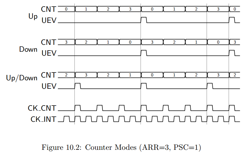
To understand the three counter modes consider Figure 10.2.
In these examples, we assume a prescaler of 1 (counter clock is half the internal clock), and a auto reload value of 3.
Notice that in “Up” mode, the counter increments from 0 to 3 (ARR) and then is reset to 0.
When the reset occurs, an “update event” is generated.
This update event may be tied to TRGO, or in more complex timers with capture/compare channels
it may have additional effects (described below).
Similarly, in “Down” mode, the counter decrements from 3 to 0 and then is reset to 3 (ARR).
In Down mode, an update “event” (UEV) is generated when the counter is reset to ARR.
Finally, in Up/Down mode, the counter increments to ARR, then decrements to 0, and repeats.
A UEV is generated before each reversal with the effect that the period in Up/Down mode
is one shorter than in either Up or Down mode.
Many timers extend this basic module with the addition of counter channels such as the one illustrated in Figure 10.3.
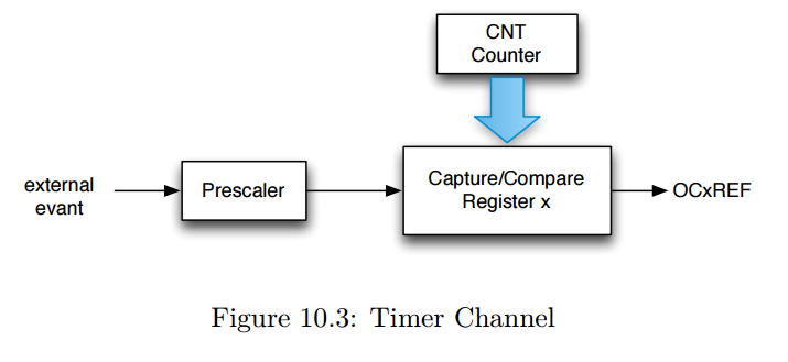
The “x” refers to the channel number – frequently, timers support multiple channels.
With this modest additional hardware, an output can be generated whenever the count register reaches a specific value
or the counter register can be captured when a specific input event occurs (possibly a prescaled input clock).
An important use of counter channels is the generation of precisely timed pulses.
There are two variations of this use – “one-pulse” pulses,
in which a single pulse is generated, and pulse width modulation, in which a series of pulses is generated with the counter UEV period.
The pulse width is controlled by the Capture/Compare Register (CCR).
For example, the channel output (OCxREF) may tied to whether the CNT register is greater (or less) than the Compare register.
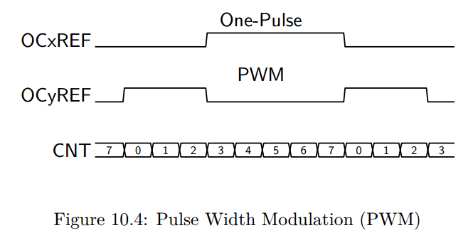
In Figure 10.4 we illustrate the use of two channels for one-pulse and PWM outputs.
Here we assume that the ARR is 7 and the CCR is 3.
In PWM mode, ARR controls the period, and CCR controls the pulse width (and hence the duty cycle).
In one-pulse mode, the pulse begins CCR cycles after an initial trigger event, and has a width of ARR-CRR.
It is possible to use multiple channels to create a set of synchronized, pulses beginning at precise delays from each other.
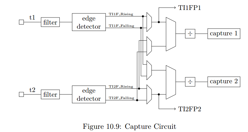
A timer channel may also be used to measure pulse widths – in effect decoding pwm signals.
There are many other configuration options for the STM32 timers including mechanisms
to synchronize multiple timers both to each other and to external signals.
In the remainder of this chapter we consider two timer applications including PWM output (Section 10.1),
input pulse measurement (Section 10.2).
In Chapter 13 we show how to use a timer to control DMA transfers for an audio player and
in Chapter 14 we use a timer to sample and analog input at regular intervals.
STM32 Timer : Base Timer, Input Capture, PWM, Output Compare的更多相关文章
- PIC32MZ tutorial -- Output Compare
Output Compare is a powerful feature of embedded world. The PIC32 Output Compare module compares the ...
- STM32 System and Timer Clock Configurations
STM32 System and Timer Clock Configurations I've started writing some software to drive a series of ...
- TIMER门控模式控制PWM输出长度
TIMER门控模式控制PWM输出长度 参照一些网友代码做了些修改,由TIM4来控制TIM2的PWM输出长度, 采用主从的门控模式,即TIM4输出高时候TIM2使能输出 //TIM2 PWM输出,由TI ...
- PIC32MZ tutorial -- Input Capture
Today I accomplish a simple application for PIC32MZ EC Starter Kit. This application uses Input Capt ...
- An Isolated DAC Using PWM Output
An Isolated DAC Using PWM Output Arduino‘s (ATmega328P) PWM outputs via analogWrite can be convenien ...
- 深入比特币原理(三)——交易的输入(input)与输出(output)
本节内容非常重要,如果你不能很好的掌握本节内容,你无法真正理解比特币的运行原理,请务必要学习清楚. 比特币的交易模型为UTXO(unspend transaction output),即只记录未花费的 ...
- Linux部署Django:报错 nohup: ignoring input and appending output to ‘nohup.out’
一.部署 Django 到远程 Linux 服务器 利用 xshell 通过 ssh 连接到 Linux服务器,常规的启动命令是 python3 manage.py runserver 但是,关闭 x ...
- STM32: TIMER门控模式控制PWM输出长度
搞了两天单脉冲没搞定,无意中发现,这个利用主从模式的门控方式来控制一路PWM的输出长度很有效. //TIM2 PWM输出,由TIM4来控制其输出与停止 //frequency_tim2:TIM2 PW ...
- STM32 Seminar 2007 -- Timer
随机推荐
- 20155328 2016-2017-2 《Java程序设计》 第8周学习总结
20155328 2016-2017-2 <Java程序设计> 第8周学习总结 教材学习内容总结 NIO与NIO2 认识NIO 相对于IO,NIO可以让你设定缓冲区容量,在缓冲区中对感兴趣 ...
- HDU 4502 吉哥系列故事——临时工计划(一维动态规划)
题意:吉哥的假期是1到n天,然后有m个工作可以让吉哥选择做,每个工作都有一个开始 t_s 和结束的时间 t_e ,都用天来表示,然后每个工作必须从第一天做到最后一天, 从头到尾做完之后就可以得到 ...
- pytorch函数之torch.normal()
Returns a Tensor of random numbers drawn from separate normal distributions who’s mean and standard ...
- fastdfs:安装nginx
#安装依赖 yum -y install gcc yum -y install gcc-c++ yum -y install zlib-devel yum -y install pcre-devel ...
- wpf image 指定Stretch="None" 不拉伸的时候,仍然拉伸的解决办法
I think TI82 is right on this issue. The image become bigger than you expect because its dpi doesn't ...
- Java编程的逻辑 (14) - 类的组合
本系列文章经补充和完善,已修订整理成书<Java编程的逻辑>,由机械工业出版社华章分社出版,于2018年1月上市热销,读者好评如潮!各大网店和书店有售,欢迎购买,京东自营链接:http: ...
- Android studio2.3.3升级3.1.2坑
原文:https://blog.csdn.net/qq_26361871/article/details/80255141 1.grade配置Error: Could not find com.and ...
- 打FFT时中发现的卡常技巧
题目:洛谷P1919 A*B Problem 加强版 我的代码完全借鉴boshi,然而他380ms我880ms...于是我通过彻底的卡(chao)常(dai)数(ma)成功优化到了380ms,都是改了 ...
- MVC底层原理
窥探ASP.Net MVC底层原理 实现跨越Session的分布式TempData 1.问题的引出 我相信大家在项目中都使用过TempData,TempData是一个字典集合,一般用于两个请求之间临时 ...
- Windows 系统采用批处理命令修改 ip 地址
Windows 系统采用批处理命令修改 ip 地址 :: 设置IP地址 set /p choice=请选择设置类型(1:外网IP / 2:内网IP / 3:自动获取IP): echo. if &quo ...