Multi-Projector Based Display Code ---- Calibration
Overview
As mentioned previously, there are two main steps in generating a seamless display. The first is camera-based calibration. This involves a user-level application that gathers the required geometric data to geometrically register each projector into the camera image coordinate space and photometric data for blending or luminance smoothing.
Be aware that the calibration procedures that collect the geometric and photometric information need to be performed only periodically whenever there is a change in the display set-up. It is not critical to perform the calibration procedure in real time. Therefore, the overall calibration procedure can often take several minutes to perform information gathering from the camera as well as the necessary computation.
Algorithms
The purpose of calibration is to build the correspondence between projector coordinate and camera coordinate. So during the calibration procedure, we project a few feature images with the coordinate of the features (white blobs in black background) in projector space manually specified. The remaining question is how to detect the features in camera image and build the correspondence between the projected features and detected features.
Detecting the feature is relatively simple. We first project feature image with all the features (all the white blobs, 10x10, for example), then we grab the camera image and convert to grey image (if original is color) and then to binary image. If the environment lighting and camera exposure are carefully tuned, all the pixels of features will be white and all other pixels will be black. Then we use the labeling algorithm to detect all connecting components in the image. The labeling algorithm is classic and you can find many introduction about it from the web. You can also refer to our codes for more details. After detecting all the connecting components, each of them is regarded as one feature. The total number of features detected should equal to the number we projected. The average coordinate of all the pixels inside the connecting component (the center of connecting component) is the coordinate of the feature in the camera image. We also record the bounded box of each feature for later detection.
The bigger challenge is to determine correspondence between the projected feature and detected feature in camera coordinates. We use a binary encoding scheme to efficiently build this correspondence. First, we assign an ID for each feature in projector coordinate, for example, 1~100 for 100 features. We rewrite this ID to binary format in 7 bits, for example, 0000111 for ID 7. Then, we project a image with all the features and grab the camera image accordingly. After analysing the image with labeling algorithm mentioned previously, we are able to record the bounded box for each feature. Next, we project a feature image for each bit (7 images for 7 bits). For each feature, if the corresponding bit of the binary format of its ID equals to 1, we show this feature (the white blob) in the feature image we are going to project; if it equals to 0, we eliminate it. The following figure shows the full feature image and one feature image for each bit. After projecting the feature image of specified bit and grabbing the camera image accordingly, we detect whether a feature is shown in the bounded box generate from the full feature image. If the feature is shown, we put a "1" in that bit of the ID associated with the feature; otherwise, we put a "0". In this way, we can recover the specified bit of all the features. After repeat this process for all the bits (7 bits for 100 features), we can recover the ID of all the features in the camera image. Now we can assure that the feature in projector is corresponding to the feature with the same ID in camera image. We associate their coordinate in projector space and camera space together and successfully build the correspondence. (You can find more details about this algorithm in reference [1])
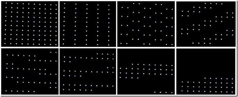
Figure 1. Projector-to-camera mapping registration procedure using binary encoding scheme
System Configuration
There are three typical configurations you might consider to play with. The first configuration is using only one projector (single-projector configuration). The second configuration is using multiple projectors, each driven by one PC (multi-projector multi-PC configuration). The third configuration is using multiple projectors driven by one PC with multiple outputs (multi-projector single-PC configuration), for example, we use four projectors driven by one PC supporting dual graphic cards while each card has dual outputs.
Single-Projector Configuration
Single projector configuration uses only one PC as both master PC and rendering PC, as shown in the following figure:
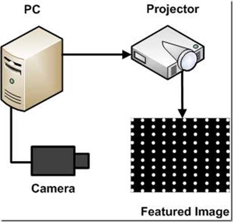
Figure 2. Single-Projector Configuration
Though this configuration could not provide a larger display (even slightly smaller than the original display area), it is very helpful for beginners to understand the structure and concept of the system. And the codes are relative simple, so they are easy to read, understand and modify. Meanwhile, the hardware involved in this configuration is limited, so it's quite straightforward to set up the system. After finish the system, you could expect that no matter how you placed the projector, the imagery in the camera view is geometrically undistorted. Since there is only one projector in this case, no photometric correction needs to be done.
Multi-Projector Multi-PC Configuration
Multi-Projector Multi-PC configuration consists of an individual master PC and one rendering PC for each projector. It's the most common and practical configuration, as shown in the following figure:
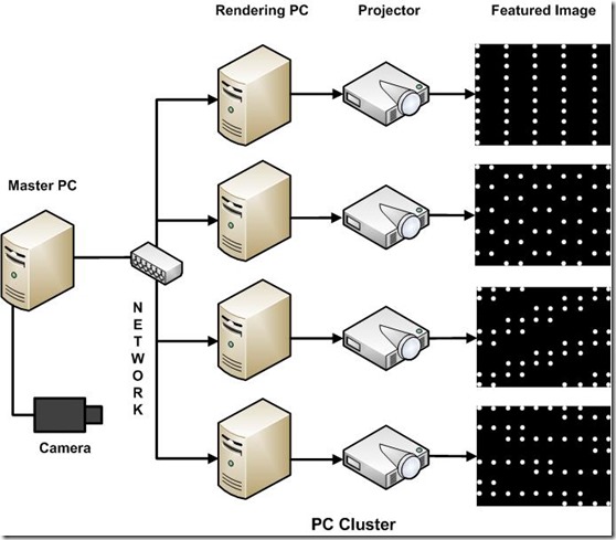
Figure 3. Multi-Projector Multi-PC Configuration
The number of rendering PCs is flexible and can vary from 1 to many. You can choose it according to your intention and available hardware (typically we adopt 4 projectors as a 2 by 2 array). All the projectors need to be registered in the camera coordinate space, so they will project the same feature images as previous configuration, one by one in the order specified in the configuration file. One result file containing geometric information and one alpha image for each projector containing photometric information will generated in the calibration procedure.
Multi-Projector Single-PC Configuration
Multi-Projector single-PC configuration uses only one PC to drive multiple projectors, as shown in the following figure:
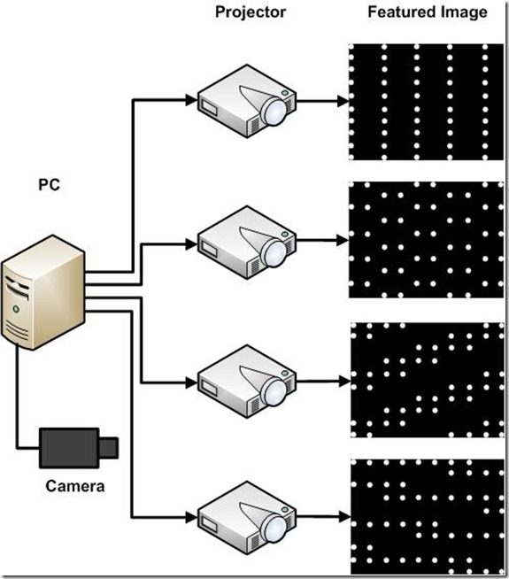
Figure 4. Multi-Projector Single-PC Configuration
There are some tricks in this configuration. It relies on the graphic card to support the function of combining all the four outputs into a large virtual desktop. Our NVIDIA GeForce 8800GTS support this feature pretty well (and I believe most mordern graphic cards do). Meanwhile, the graphic memory on the two card are isolated and any geometric or photometric correction that need to refer to the pixels in the texture buffer of the other card is impossible. This is not a problem in the Calibration and Image Viewer application, but it lead to the 3D Model Viewer unrealistic under this configuration.
Download
Please go to the downloadpage.
How to use the code
Before you start, you should first choose the configuration you would like to adopt according to your intention and available hardware. Single-projector configuration is simplified and requires the minimum hardware, so it is a good place to start with. Multi-projector multi-PC configuration is the practical configuration and should be tried out ultimately if you have enough PCs and projectors. Multi-projector single-PC configuration is helpful to understand the calibration technology and easy to set up if you have the required graphics cards. Below are the step-by-step instructions about how to use the code.
Single-Projector Configuration:
- Download the binary package named Calibration from the above "Download" Section;
- Connect the PC, projector and camera as showed in Figure 2;
- Make sure that the driver of the camera is properly installed and can be supported by OpenCV;
- Make sure that the camera is placed properly that it can see the whole display area of the projector and no obstructing white and/or bright object is in the camera's view;
- Run the calibration program from command line with:
Calibration.exe result.txt pic.bmp - If everything goes well, you will see the calibration procedure goes on and finally the pic.bmp shown on screen;
- In less than one minute, you will get the calibration result from the file result.txt at the same directory.
Multi-Projector Multi-PC Configuration:
- Download the corresponding binary package named CalibClient (control client running on master PC) and CalibServer(render server running on render PC) from the above "Download" Section;
- Connect the PCs, projectors and camera as showed in Figure 3;
- Make sure that the driver of the camera is properly installed and can be supported by OpenCV;
- Make sure that the camera is placed properly that it can see the whole display area of all the projectors and no obstructing white and/or bright object is in the camera's view;
- Run the following program on all the rendering PC from command line with:
RenderServer.exe - Modify the configuration file named Client4.cfg with the help of the comments according to your actual configuration (IP address, port, etc);
- Run the control client program on the master PC from command line with:
CalibClient.exe Client4.cfg - If everything goes well, you will see the calibration procedure goes on;
- In a few minutes, you will get the calibration result from the file result2x2.txt (as specified in the configuration file) and the alpha image named Px.bmp at the same directory.
Multi-Projector Single-PC Configuration:
- Download the corresponding binary package named MMonCalibration from the above "Download" Section;
- Connect the PCs, projectors and camera as showed in Figure 4;
- Make sure that the driver of the camera is properly installed and can be supported by OpenCV;
- Make sure that the camera is placed properly that it can see the whole display area of all the projectors and no obstructing white and/or bright object is in the camera's view;
- Make sure that you have multiple graphics cards installed properly;
- From the desktop of your Windows XP, go to "Right-Click->Properties->Settings", enable all the connected monitors by select the "Extend my Windows desktop onto this monitor" check box; Make sure the top left projector is set as primary display and drag the monitor icons to match the physical arrangement;
- Run the following program on the PC from command line with:
MMonCalibration.exe 2 2 result.txt - If everything goes well, you will see the calibration procedure goes on;
- In a few minutes, you will get the calibration result from the file resul.txt (as specified in the command line) and the alpha image named Px.bmp at the same directory.
Multi-Projector Based Display Code ---- Calibration的更多相关文章
- Multi-Projector Based Display Code ------- Home
Overview This project provides you with the tools and techniques you need to create your own large-a ...
- Multi-Projector Based Display Code ---- ImageViewer
Overview Image viewer is a typical application for large display. It makes use of the high-resolutio ...
- Multi-Projector Based Display Code ---- FAQ
Frequently Asked Question How do I know that my camera has a proper lens? Answer: If you can see exa ...
- Multi-Projector Based Display Code ---- ModelViewer
Overview Model viewer is another application we provided for large display. It is designed for viewi ...
- Multi-Projector Based Display Code ---- Download
The code providing are for your reference. Please download the code according to your hareware confi ...
- 160多条Windows 7 “运行”命令
160多条Windows 7 “运行”命令: 删除或更改应用程序 = control appwiz.cpl 添加设备 = devicepairingwizard 蓝牙文件传输 = fsquirt ...
- Peer Code Reviews Made Easy with Eclipse Plug-In
欢迎关注我的社交账号: 博客园地址: http://www.cnblogs.com/jiangxinnju/p/4781259.html GitHub地址: https://github.com/ji ...
- Code Pages
https://docs.microsoft.com/en-us/windows/desktop/intl/code-pages Most applications written today han ...
- 设备管理 USB ID
发现个USB ID站点,对于做设备管理识别的小伙伴特别实用 http://www.linux-usb.org/usb.ids 附录: # # List of USB ID's # # Maintain ...
随机推荐
- WebApi用JilFormatter处理客户端序列化的字符串加密,之后在服务端解析。
本文有改动,参考原文:https://www.cnblogs.com/liek/p/4888201.html https://www.cnblogs.com/tonykan/p/3963875.htm ...
- matplotlib中的plt.ion()和plt.ioff()函数
转自https://blog.csdn.net/yzy__zju/article/details/85008603 Matplotlib的显示模式默认为阻塞(block)模式,因此若想动态显示图像,则 ...
- Spring Cloud 2-Feign 声明式服务调用(三)
Spring Cloud Feign 1. pom.xml 2. application.yml 3. Application.java 4. Client.java 简化RestTemplate调 ...
- 写给自己看的新手java-环境配置
环境:win10. 第一步:下载jdk (类似于 net framework ) 环境运行库.地址:http://www.oracle.com/technetwork/java/javase/down ...
- web开发简史与技术选型
视频地址:http://v.youku.com/v_show/id_XMTQxNzM1MzAwOA==.html?firsttime=0&from=y1.4-2
- I2C与EEPROM
一.基本概念 RAM(Random Access Memory)的全名为随机存取记忆体,它相当于PC机上的移动存储,用来存储和保存数据的.它在任何时候都可以读写,RAM 通常是作为操作系统或其他正在运 ...
- Mysql --数据库概述1
什么是数据(Data)? 描述事物的符号记录称为数据,描述事物的符号既可以是数字,也可以是文字.图片,图像.声音.语言等,数据由多种表现形式,它们都可以经过数字化后存入计算机 在计算机中描述一个事物, ...
- css 冷知识
*{margin: 0;padding: 0;} li{list-style-type:none; }ul{list-style: none;}img{border: none;}ul,input,s ...
- iOS -- Effective Objective-C 阅读笔记 (6)
1: 在 既有类中使用 关联对象存放自定义数据 有时候需要在对象中存放相关信息, 这是我们经常会从对象所属的类中继承一个子类, 然后改用这个子类对象, 然而并非所有的情况下都能这么做, 有时候类的实 ...
- 爬虫框架 Scrapy
一 介绍 crapy一个开源和协作的框架,其最初是为了页面抓取 (更确切来说, 网络抓取 )所设计的,使用它可以以快速.简单.可扩展的方式从网站中提取所需的数据.但目前Scrapy的用途十分广泛,可用 ...