STM32 Timer Clock sources -- External Clock Both Edge
Timers get their clock source from External pins or Internal timer sources.
External
External = pins: TI1 or TI2 or ETR
- set pin to be used:
- in TIMx_CCMR1 reg - set pin to be used by writing CCxS bits
- select polarity of input
- in TIMx_CCER reg - write CCxP and CCxNP to select rising, falling or both edges
- select external clock mode1
- in TIMx_SMCR reg - write SMS=111
- optionally configure filter and prescaler
- in TIMx_CCMR1 - write ICxF[3:0] bits
- optionally set trigger input source as Timer TIx
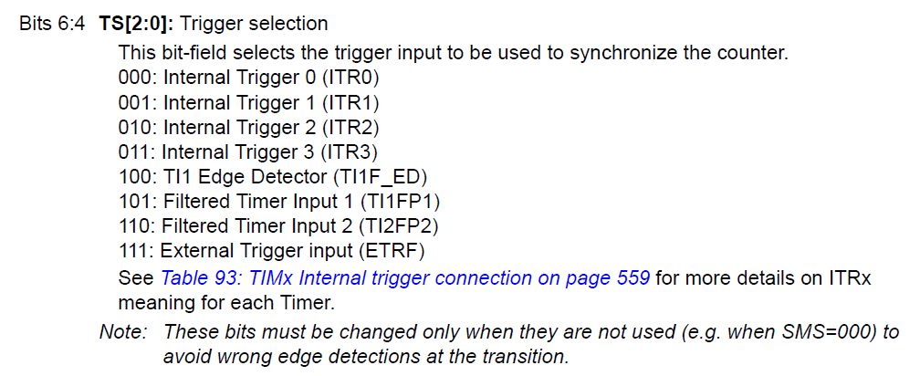
- in TIMx_SMCR reg - write TS bits
- Enable channel
- in TIMx_CCER reg - set CCEx bit
If ETR is to be input clock:
- set clock mode2
- in TIMx_SMCR reg - set ECE=1
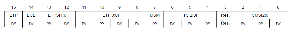
- configure prescaler, filter, polarity
- in TIMx_SMCR reg - set ETPS[1:0], ETF[3:0], ETP
Internal
One Timer can be used as the prescaler for another.
The first timer update_event, or output_compare signal is used as clock for the second. Uses TRGI to map. Counter mode is set using the TIMx_CR1 reg and CMS bits as indicated in the example below. The counter mode sets whether the update_event occurs on overflow and/or underflow of the Timer.
Clock source selection
This is one of the difficulties. From the manual, we see that there are three clock sources:
1, the internal clock.
To do is to choose CK_INT clock, this simple, but it must be noted,
the timer clock is not directly from the APB1 or domain (APB2) of but from input APB1 or APB2, a frequency multiplier,
when APB1 prescaler factor of 1, the frequency multiplier does not work, the clock frequency of the timer equal to the APB1 frequency;
When the prescaler APB1 coefficient for the other values (ie prescaler factor of 2, 4, 8, or 16),
the times The frequency function, the timer clock frequency equal to twice the frequency of the APB1.
Such as AHP 72M, APB12 frequency of 36M, then TIMER is APB1 multiplied by 2, that is 72M.
How to select clock mode? As long as the the SMCR SMS [2:0] inflicted 000 just fine
2, the external clock mode 1
This is too much trouble, clock source selection is actually TRGI (trigger input),
but a lot of trigger input selection, a total of eight ......
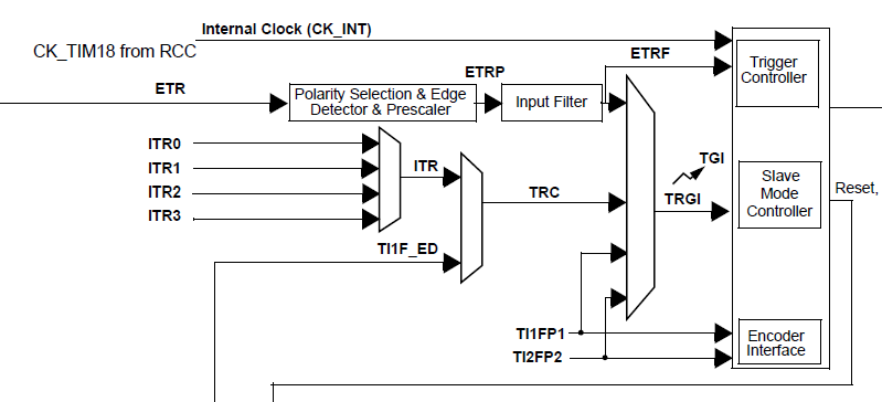
See block diagram, they by: ITRx TI1F_ED, TI1FP1, TI2FP2, ETRF
ITRx things timer cascade, whether he temporarily.
To enter the This clock mode first set SMS 111, of course, this does not end, unlike the internal clock, anything with a good,
here you have to configure other parameters, such as TI1FP1 choose natural input channel 1 configuration parameters,
so that the clock can come in the way you need. Is equipped with block diagram of this
In the CCMR1 register select the corresponding input the (The CC1S) good and filter (IC1F)
and then configure input polarity the SMCR (CC1P)
and then select the trigger source (TS [2:0]) for TI1 input channel with a good the final choice of SMS is 111, the clock (CR1 CEN).
Now the clock is input from TI1, can count like a clock source.
Similarly, if use it ETR channel with a good on it.
3, the external clock mode 2
Select the external input as the clock, see block diagram:
As can be seen from FIG ETR can be directly used as the clock input can also trigger input (TRGI) as a clock input,
the clock mode 1 trigger source is selected as the ETR, two effects are the same,
it looks like this external clock mode useless, in fact, is not the case,
he can tell from the mode (reset, triggered, gated) combination.
When triggered mode is selected, for example, we can no longer ETR selected trigger source,
because the slave mode controller is accounted for,
fortunately there is the external clock mode 2, we have chosen this mode
after a combination of both in with the completion of some of the features.
Summarize the STM32 clock selection rather special, no longer a clock configuration bits in SFR,
not to say the two together 00, 01, but by the selected
SMCR SMS and ECE to control, to feel this way can the internal clock and the external mode open at the same time
(SMS: 000, ECE: 1) can also be external mode and external mode at the same time open (SMS: 111, ECE: 1 ),
in fact, the above two methods are used in an external clock.

2.1 Clock input sources
The timer can be synchronized by several clocks simultaneously:
Internal clock
External clock
– External mode1 (TI1 or TI2 pins)
– External clock mode2 (ETR pin)
– Internal trigger clock (ITRx)
2.1.1 Internal clock
The timer is clocked by default by the internal clock provided from the RCC.
To select this clock source, the SMCR_SMS (if present) bits should be reset.
2.1.2 External clock
The external clock timer is divided in two categories:
External clock connected to TI1 or TI2 pins
External clock connected to ETR pin
In these cases, the clock is provided by an external signal connected to TIx pins or ETR pin.
The maximum external clock frequency should be verified.
Note:
1 In addition to all these clock sources, the timer should be clocked with the APBx clock.
2 The external clocks are not directly feeding the prescaler, but they are first synchronized with the APBx clock through dedicated logical blocks.
External clock mode1 (TI1 or TI2 pins)
In this mode the external clock will be applied on timer input TI1 pin or TI2 pin. To do this:
1.Configure the timers to use the TIx pin as input:
a) Select the pin to be used by writing CCxS bits in the TIMx_CCMR1 register.
b) Select the polarity of the input:
For the STM32F100/101/102/103/105/107 lines: by writing CCxP in the TIMx_CCER register to select the rising or the falling edge
For the STM32F100/101/102/103/105/107 lines, polarity selection for both edges can be achieved by using TI1F_ED, but only for TI1 input.
For the other series & lines: by writing CCxP and CCxNP in the TIMx_CCER register to select the rising/falling edge, or both edges.
c) Enable the corresponding channel by setting the CCEx bit in the TIMx_CCER register.
2. Select the timer TIx as the trigger input source by writing TS bits in the TIMx_SMCR register.
3. Select the external clock mode1 by writing SMS=111 in the TIMx_SMCR register.
CC1NP/CC1P bits

slave mode : disabled, reset, external clock, trigger, gated or encoder mode( 1,2,3 )

rising or falling edge for capture or slave mdoe in reset, external clock or trigger mode

inverted or not level for slave mdoe in gated mode or encoder mode

CC1NP/CC1P bits select the active polarity of TI1FP1 and TI2FP1 for trigger or capture operations.

00: rising edge  : sensitive to TIxFP1 rising edge

00: non-inverted : TIxFP1 is not inverted

01: falling edge : sensitive to TIxFP1 falling edge

01: inverted     : TIxFP1 is inverted

10: reserved, do not use this configuration.

11: both edges   : sensitive to both TIxFP1 rising and falling edges

11: non-inverted : TIxFP1 is not inverted

This configuration must not be used in encoder mode.

External clock mode2 (ETR pin)
The external clock mode2 uses the ETR pin as timer input clock. To use this feature:
1.Select the external clock mode2 by writing ECE = 1 in the TIMx_SMCR register.
2. Configure, if needed, the prescaler, the filter and the polarity by writing ETPS [1:0], ETF [3:0] and ETP in the TIMx_SMCR register.
Internal trigger clock (ITRx)
This is a particular mode of timer synchronization.
When using one timer as a prescaler for another timer, the first timer update event or output compare signal is used as a clock for the second one.
stm32f2xx external clock source for timer
I trying to use a timer with an external clock source on a stm32f207ZE microcontroller. But it isn't working. Here is my code:
/* TIM1 clock enable */

  RCC_APB2PeriphClockCmd(RCC_APB2Periph_TIM1, ENABLE);

  /* GPIOE clock enable */

  RCC_AHB1PeriphClockCmd(RCC_AHB1Periph_GPIOE, ENABLE);

  /* GPIOE Configuration: PE.11(TIM1 CH2)  */

  GPIO_InitStructure.GPIO_Pin = GPIO_Pin_11;

  GPIO_InitStructure.GPIO_Mode = GPIO_Mode_AF;

  GPIO_InitStructure.GPIO_Speed = GPIO_Speed_100MHz;

  GPIO_InitStructure.GPIO_OType = GPIO_OType_PP;

  GPIO_InitStructure.GPIO_PuPd = GPIO_PuPd_NOPULL;

  GPIO_Init(GPIOE, &GPIO_InitStructure);

  GPIO_PinAFConfig(GPIOE, GPIO_PinSource11, GPIO_AF_TIM1);

  GPIO_PinAFConfig(GPIOE, GPIO_PinSource7, GPIO_AF_TIM1);

  /* TIM1 Input trigger configuration: External Trigger connected to TI2 */

  TIM_ICInitStructure.TIM_Channel = TIM_Channel_2;

  TIM_ICInitStructure.TIM_ICPolarity = TIM_ICPolarity_Rising;

  TIM_ICInitStructure.TIM_ICSelection = TIM_ICSelection_DirectTI;

  TIM_ICInitStructure.TIM_ICPrescaler = TIM_ICPSC_DIV2;

  TIM_ICInitStructure.TIM_ICFilter = 0x0;

  TIM_ICInit(TIM1, &TIM_ICInitStructure);

  TIM_TIxExternalClockConfig (TIM1, TIM_TS_TI2FP2, TIM_ICPolarity_Rising, ) ;

  TIM_SelectSlaveMode(TIM1, TIM_SlaveMode_External1);

  TIM_Cmd (TIM1, ENABLE);

  Where can be my mistake?
  I have some misunderstanding on what source pin must be used for Timer1 TI2.
  Is it the same that Timer1_CH2?

  I also tried ETR mode by inizializing ETR pin

  /* TIM1 clock enable */

  RCC_APB2PeriphClockCmd(RCC_APB2Periph_TIM1, ENABLE);

  /* GPIOE clock enable */

  RCC_AHB1PeriphClockCmd(RCC_AHB1Periph_GPIOE, ENABLE);

    /* GPIOE Configuration: PE.7(TIM1 ETR)  */

  GPIO_InitStructure.GPIO_Pin = GPIO_Pin_7;

  GPIO_InitStructure.GPIO_Mode = GPIO_Mode_AF;

  GPIO_InitStructure.GPIO_Speed = GPIO_Speed_100MHz;

  GPIO_InitStructure.GPIO_OType = GPIO_OType_PP;

  GPIO_InitStructure.GPIO_PuPd = GPIO_PuPd_NOPULL;

  GPIO_Init(GPIOE, &GPIO_InitStructure);

  GPIO_PinAFConfig(GPIOE, GPIO_PinSource7, GPIO_AF_TIM1);

    TIM_TimeBaseStructure.TIM_Period = 0xFFFF;      // 5000*20 uS - 100 ms

    TIM_TimeBaseStructure.TIM_Prescaler = ;    // frequency - 20 MHz

    TIM_TimeBaseStructure.TIM_ClockDivision = ;

    TIM_TimeBaseStructure.TIM_CounterMode = TIM_CounterMode_Up;

    TIM_TimeBaseInit(TIM1, &TIM_TimeBaseStructure);

    //for ETR IN RM0033 p. 372

    TIM1->SMCR = ;

    TIM1->SMCR |= TIM_ExtTRGPSC_DIV4; //2. set prescaller

    TIM1->SMCR |= TIM_ICPolarity_Rising; //3. rising edge

    TIM1->SMCR |= 0x4000; // 4. Enable external clock mode 2 by writing ECE=1

  TIM_Cmd (TIM1, ENABLE);
But it also doesn't work.
Maybe frequency is to high?
And i saw some strnge behaviour. When i inizialize once more counter:
void inizializeSimpleCounter(){

  NVIC_InitTypeDef                  NVIC_InitStructure;

    TIM_TimeBaseInitTypeDef     TIM_TimeBaseStructure;

/****************Timer4 Inizialization**************************/

    RCC_APB1PeriphClockCmd(RCC_APB1Periph_TIM4, ENABLE);

    TIM_TimeBaseStructure.TIM_Period = ;        // 5000*20 uS - 100 ms

    TIM_TimeBaseStructure.TIM_Prescaler = -;  // frequency - 20 MHz

    TIM_TimeBaseStructure.TIM_ClockDivision = ;

    TIM_TimeBaseStructure.TIM_CounterMode = TIM_CounterMode_Up;

    TIM_TimeBaseInit(TIM4, &TIM_TimeBaseStructure);

    TIM4->DIER = TIM_DIER_UIE;

    TIM_Cmd(TIM4, ENABLE);

    NVIC_InitStructure.NVIC_IRQChannel =  TIM4_IRQn;

    NVIC_InitStructure.NVIC_IRQChannelPreemptionPriority = 0x01;

    NVIC_InitStructure.NVIC_IRQChannelSubPriority = 0x03;

    NVIC_InitStructure.NVIC_IRQChannelCmd = ENABLE;

    NVIC_Init(&NVIC_InitStructure);

/*************************************************************/

}
The timer, which was initialize to count from extrenal counter counts some values, and then stops
Some external source with frequency 20 MHz is connected to this pin.
I expext that counter will begin to count - so the value in TIM1->CNT register will increment. But nothing counts
It seems that error was in schematic. Inizialization is right
I had the same problem but solved it with the code below:
TIM2->SMCR =0x0067;

TIM2->CCMR1=0x0100;

TIM2->CCER=0x0010;

TIM2->CNT = 0x1;
STM32 Timer Clock sources -- External Clock Both Edge的更多相关文章
- STM32 F4 Clock Sources
STM32 F4 Clock Sources Goal: routing clock sources to the microcontroller output pin (MCO1) High- ...
- STM32F4 Timer External Clock TI2 Both Edges Demo
#define CLK_FREQ ( 10000 ) #define CORE_FREQ ( 168000000 ) static void TIM_GPIO_Config( void ) { GPI ...
- STM32 Timer : Base Timer, Input Capture, PWM, Output Compare
http://www.cs.indiana.edu/~geobrown/book.pdf An example of a basic timer is illustrated in Figure 10 ...
- STM32——timer
原文地址: http://blog.sina.com.cn/s/blog_49cb42490100s6ud.html 1. STM32的Timer简介 STM32中一共有11个定时器,其中 ...
- CTS 如何处理 gating clock 和 generated clock
1. CTS 时会将 ICG cell 作为 implicit nostop pin 处理,直接穿透,以 ICG cell 后面的 sink 点作为真正的 sink 来长 tree 2. CTS 时会 ...
- STM32:TIMER PWM 输入检测
PWM输入检测是输入捕获的一个特例,可以测量频率与占空比 与输入捕获不同的是PWM输入模式会将同一个输入信号(TI1或TI2)连接到两个捕获装置(IC1和IC2).这两个捕获装置一个捕获上升沿一个捕获 ...
- STM32: TIMER门控模式控制PWM输出长度
搞了两天单脉冲没搞定,无意中发现,这个利用主从模式的门控方式来控制一路PWM的输出长度很有效. //TIM2 PWM输出,由TIM4来控制其输出与停止 //frequency_tim2:TIM2 PW ...
- STM32 TIMER OUTPUT DIAGRAM
- STM32 TIMER DIAGRAM
随机推荐
- 20155306 2016-2017-2 《Java程序设计》第八周学习总结
20155306 2016-2017-2 <Java程序设计>第八周学习总结 教材学习内容总结 第十五章 通用API 15.1 日志 java.util.loggging包提供了日志功能相 ...
- 第7月第11天 AVAsset
1. An AVAsset defines the collective properties of the tracks that comprise the asset. (You can acce ...
- Django之模板语法
Django框架之第三篇模板语法(重要!!!) 一.什么是模板? 只要是在html里面有模板语法就不是html文件了,这样的文件就叫做模板. 二.模板语法分类 一.模板语法之变量:语法为 {{ }}: ...
- caoha
- linux backtrace()详细使用说明,分析Segmentation fault【转】
转自:http://velep.com/archives/1032.html 在此之前,开发eCos应用程序时,经常碰到程序挂掉后,串口打印输出一大串让人看不懂的数据.今天才明白,原来这些数据是程序挂 ...
- css部分复习整理
CSS代码语法 css 样式由选择符和声明组成,而声明又由属性和值组成,如下图所示: 选择符:又称选择器,指明网页中要应用样式规则的元素,如本例中是网页中所有的段(p)的文字将变成蓝色,而其他的元素( ...
- TcxGrid 标题头高度
- JS模块化编程(一):CommonJS,AMD/CMD
前言 模块化是什么? 为什么采用模块化? 场景: 一个html,因不同的业务需求开发,会不断的引入js文件.另外,a.js和b.js中的变量或函数必须是全局的,才能暴露给使用方. <script ...
- SCU 4438:Censor
Censor frog is now a editor to censor so-called sensitive words (敏感词). She has a long text p . Her j ...
- 3.操作jQuery集合《jquery实战》
3.1 创建HTML元素 使用 jquery 创建动态元素是相当容易的.可以通过 $() 函数包含一个 HTML 标签的字符串来创建. $('<div>Hello</div>' ...