PatentTips - MPLS Network System
MPLS (Multi Protocol Label Switching) network system has been watched with keen interest as a technique of speeding up a packet forwarding process (packet switching process) in an IP (Internet Protocol) network such as the Internet. MPLS is the protocol enabling a forwarding target packet such as an IP packet to be routed based on a 20-bit label attached to this packet inside the MPLS network in a way that assembles an MPLS frame by attaching an MPLS header containing the 20-bit label to the packet.
MPLS enables higher-speed packet routing with timesaving not via the network layer than by normal routing based on a routing table on the network layer, i.e., by routing based on a search for an IP address. Further, MPLS can be utilized as an infrastructure for configuring VPN (Virtual Private Network) and is therefore watched with keen interest by carriers (common carriers or communication service providers). MPLS is expected to spread from now into the future.
Herein, FIG. 1 illustrates how the packet (IP packet) is routed (packet switching) on an MPLS-based network layer. Referring to FIG. 1, in this MPLS network system, provider networks having IP addresses (Prefix) [a] and [d] as user sites are connected to the MPLS network. These provider networks accommodate terminal devices such as personal computers given IP addresses [A] and [D], respectively.
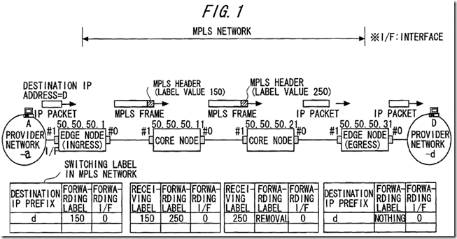
Ingress and egress edge nodes and respective switching nodes (core or internal nodes) within the MPLS network build a label switched path (LSP) in the MPLS network by use of LDP (Label Distribution Protocol) for distributing an MPLS label.
The respective nodes create and retain routing tables (label tables) as shown in FIG. 1. Each of the routing tables retained by the ingress and egress edge nodes is stored with pieces of information such as a destination IP address (Prefix), a forwarding label and a forwarding interface. The routing table retained by each of the switching nodes is stored with pieces of information such as a receiving label, a forwarding label and a forwarding interface.
After building the label switched path, the ingress edge node in the MPLS network forwards to the posterior switching node an MPLS frame (MPLS packet) assembled by attaching an MPLS header containing an IP packet switching label (forwarding label) to the IP packet, and thereafter the forwarding target packet is routed by label switching based on the IP packet switching label down to the egress edge node.
Next, FIG. 2 illustrates network layer protocol-based packet (IP packet) routing in the case of configuring VPN using MPLS. Referring to FIG. 2, in this MPLS network system, user networks having IP addresses (Prefix) [a] and [c] as user sites are connected to the MPLS network. These user networks accommodate terminal devices such as personal computers given IP addresses [A] and [C], respectively.
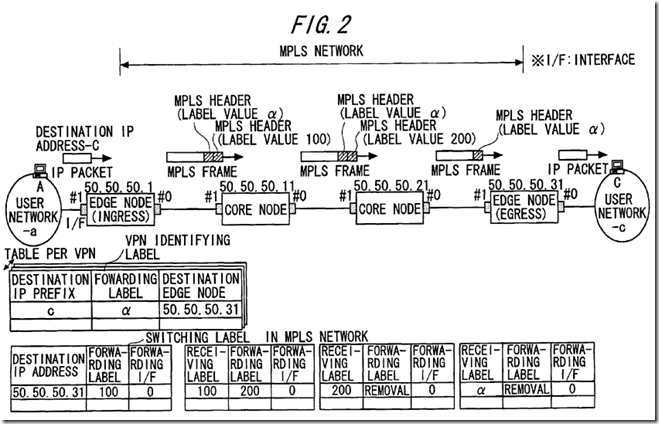
The ingress edge node, the egress edge node and the respective switching nodes in the MPLS network build an IP packet routing label switched path and a VPN label switched path in the MPLS network by utilizing LDP for distributing the MPLS label and mp-BGP (multiprotocol-Extension Border Gateway Protocol).
The ingress edge node creates and retains a VPN label table as shown in FIG. 2. This VPN label table is created for every VPN, i.e., every virtual path and is stored with pieces of information such as a destination IP address (Prefix), a forwarding label and IP address of a destination edge node.
The respective nodes create and retain routing tables as shown in FIG. 2. The routing table retained by the ingress edge node is stored with pieces of information such as a destination IP address, a forwarding label, and a forwarding interface. Each of the routing tables retained by the respective switching nodes and the egress edge node, is stored with pieces of information such as a receiving label, a forwarding label and a forwarding interface.
After building the label switched path, the ingress edge node in the MPLS network forwards to the posterior switching node an MPLS frame assembled by attaching two pieces of MPLS headers containing an IP packet switching label (forwarding label) and a VPN identifying label to the IP packet, and thereafter the forwarding target packet is routed by label switching based on the IP packet switching label and the VPN identifying label down to the egress edge node.
On the other hand, in the carrier network, it is of importance to increase a capacity of the network and to enhance a reliability, and a variety of existing load sharing techniques are applied for actualizing these targets. What is focussed on here in is “trunking” defined as a technique for load sharing at a physical link level.
Trunking is a generic term of techniques of aggregating a plurality of physical links between adjacent nodes into one logical link. The techniques for attaining this are those depending on vendors, “Link Aggregation” of Ethernet that is defined by IEEE.P802.3ad, and so on.
The following advantages are obtained by utilizing the trunking technique.
(1) The plurality of physical links are bundled, and it is therefore possible to build a larger-capacity link than an upper limit of a transmission speed of one single physical link.
(2) Further, if a fault occurs on a certain physical link, the data communications can be performed through the remaining physical links bundled as the logical link, whereby the reliability can be enhanced.
FIG. 3 is an explanatory diagram showing how a frame is forwarded to the plurality of physical links bundled by trunking. Routing modules shown in FIG. 3 are, however, components given because of illustrated nodes #1, #2 being categorized as switching nodes but are not directly related to trunking.
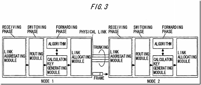
Referring to FIG. 3, there will be explained processes in the respective nodes in the case of forwarding the frame from the node #1 to the node #2. For an explanatory convenience, the discussion starts with touching on a process in a switching phase of the node #1. The routing module is defined as a routing module in bridge on, e.g., Ethernet, and searches a learning table with an in-frame destination MAC address used as a key, thereby determining a destination link.
A calculation key generating module, if the link determined as a destination by this routing module is one of the plurality of physical links (aggregated as one logical link) undergoing trunking, in a forwarding phase, performs a calculation based on a predetermined algorithm by inputting (information in) a header of the frame, and outputs a calculation key.
A link allocating module, based on this calculation key, selects one of the plurality of physical links bundled as one logical link and forwards the frame to this selected physical link.
Next, a process in a receiving phase will be explained. In the node #2 receiving the frame from one of the physical links, a link aggregating module recognizes that the frame is received from the logical link corresponding to the receiving physical link.
Thus, the frame forwarding node #1 allocates the frames, addressed to one logical link, to the plurality of physical links, thereby actualizing the load sharing.
With respect to the algorithm adopted by the calculation key generating module, the following points need to be given heed to. (1) Namely, the traffic is distributed efficiently so that the load concentrates on one physical link among the plurality of candidate physical links. (2) Further, when a series of one-way traffic flowing from the same source to the destination is defined as “flow” in a session of communications performed on every application (e.g., every application layer protocol such as Telnet, FTP (File Transfer Protocol), SMTP (Simple Mail Transfer Protocol) and so on), the calculation keys of the frames belonging to the same flow take the same value so that the frames belonging to one flow are allocated to the same physical link.
The reason for the necessity of considering the heeding point (2) is that if the node #1 forwards the frames belonging to the same flow in distribution to different physical links, the node #2 is unable to recognize that the frames belong to the same flow. As a result, a problem is that the sequence of the frames belonging to the single flow can not be assured in the process of routing. This problem is known as a “reverse of sequence”.
What is effective as an approach for allocating the frames while considering the heeding points (1) and (2) described above, may be such a scheme that the algorithm adopted by the calculation key generating module uses, for instance, an irreversible one-way function (e.g., Hash function) using, as inputs, values in source and destination address fields (Mac address in the case of a MAC frame, and source and destination IP addresses in the case of an IP packet (frame)) contained in the frame header, and the link allocating module allocates the frame to any one of the plurality of trunking-target physical links on the basis of the obtained key value (Hash value as a pseudo random number).
In this case, the frames belonging to the same flow are given assurance to be forwarded to the same physical link and are, it follows, properly allocated depending on Hash functions.
A case will be next considered, wherein the MPLS frame undergoes a calculation key generating process and a link allocating process in order to attain trunking described above.
MPLS is at first defined as the protocol enabling (information based on) various categories of protocols to be padded to the tail of the MPLS header.MPLS is further defined as the protocol having such a characteristic and an advantage that the frame attached once with the MPLS label (a packet switching label) can be routed based on only the MPLS header consisting mainly of this label. A value of this label is generally mapped not from a source address but from a destination address in the header of the frame before being attached with the label.
What is herein thought of is a case of generating the calculation key for allocating the MPLS frames to the physical links using the trunking technique. In this case, when generating the calculation key in a way that inputs the MPLS label, the label does not contain a piece of source identifying information, and therefore all the frames belonging to the flow streaming to the same destination come to have the same calculation key, with the result that these frames are allocated to the same physical link.
FIG. 4 is an explanatory view illustrating this problem with the aid of a specific example. FIG. 4 shows an example of architecture of an MPLS network system, wherein VPN is configured between user networks #1, #2, #3 by utilizing MPLS, and a label value α is mapped to and address in the user network #3.
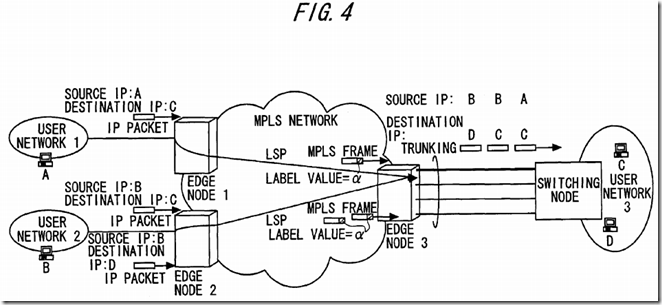
Namely, the label value in the frame is [α] on a label switched path LSP that connects the user network #1 to the user network #3 and on a label switched path LSP that connects the user network #2 to the user network #3. Note that the actual frame, when configuring VPN, flows as the frame attached with two pieces of labels just before an egress edge node as shown in FIG. 2 but is illustrated herein as the MPLS frame attached with one label value in FIG. 4 because of paying attention to only the egress edge node.
In this MPLS network system, when the IP packets are sent from the user networks #1, #2 to the destination user network #3, the respective IP packets are forwarded as the MPLS frames each having the label value a to the egress edge node (the edge node #3) from the ingress edge nodes (the edge nodes #1, #2) in the MPLS network.
IN the egress edge node, when calculating the calculation key for the label value α, a result of this calculation becomes a fixed value a t all times, with the result that all the frames destined for the user network #3 are forwarded to the same physical link (which is, for instance, the physical link, depicted by a bold line, connected to the switching node (a router etc) accommodated in the user network #3 in FIG. 4. This leads to a problem in which the load sharing is not attained.
An approach for obviating this load sharing problem is that the label value of the MPLS frame is mapped not from only the destination identifying information but from both of the source identifying information and the destination identifying information. In this case, however, initially a negotiation may take place for every destination identifying information/label pair on the occasion of building the label switched path, and a traffic for the label distribution increases corresponding to a finer level of mapping. This approach therefore causes a fresh problem.
Another approach to the load sharing problem is that pieces of information in source and destination address fields of a higher-order header than MPLS are used as inputs of the calculation key generating module in the egress edge node in FIG. 4. In this case, however, the egress edge node in the MPLS network needs to distinguish a higher-order protocol than MPLS and extract the source and destination address fields by analyzing the header.
Under such a circumstance that the various categories of protocols can be stacked on MPLS, the problem is that the header analysis per protocol is required, and this process is time-consuming. Further, there is lost the MPLS's fundamental merit that MPLS enables packet routing based on only the MPLS header, and therefore the approach described above has the problem.
SRC=http://www.freepatentsonline.com/7307991.html
PatentTips - MPLS Network System的更多相关文章
- xerox Network system
XNS协议 IPX/SPX 是基于施乐的XEROX’S Network System(XNS)协议,而SPX是基于施乐的XEROX’S SPP(Sequenced Packet Protocol:顺序 ...
- PatentTips - Method and system for browsing things of internet of things on ip using web platform
BACKGROUND The following disclosure relates to a method and system for enabling a user to browse phy ...
- PatentTips - Hierarchical RAID system including multiple RAIDs
BACKGROUND OF THE INVENTION The present invention relates to a storage system offering large capacit ...
- PatentTips - Modified buddy system memory allocation
BACKGROUND Memory allocation systems assign blocks of memory on request. A memory allocation system ...
- Residential Gateway System for Home Network Service
Disclosed herein is a Residential Gateway (RG) system for home network service. The RG system receiv ...
- MPLS
Multiprotocol Label Switching From Wikipedia, the free encyclopedia "MPLS" redirects here. ...
- Network architecture for minimalistic connected objects
In one embodiment, a network architecture comprises minimalistic connected objects (MCOs), distribut ...
- Network Function Virtualization for a Network Device
An apparatus for performing network function virtualization (NFV), comprising: a memory, a processor ...
- Multiprotocol Label Switching (MPLS)
Posted by: Margaret Rouse WhatIs.com Contributor(s): Robert Sturt This definition is part of our E ...
随机推荐
- destoon 后台入口文件分析
<?php/* [Destoon B2B System] Copyright (c) 2008-2015 www.destoon.com This is NOT a freeware, use ...
- Servlet注意事项
注意事项 1.对于Servlet的应用程序的目录结构来说,若想让有些文件Servlet可以访问,而用户不能访问的时候,可以将其放置在WEB-INF目录下 2.ServletResponse中getwr ...
- ax=1(%b) 求最小逆元
定理一:如果d = gcd(a, b),则必能找到正的或负的整数x和y,使 d = a*x+ b*y. 定理二:若gcd(a, b) = ,则方程ax ≡ c (mod b)在[, b-]上有唯一解. ...
- servlet 作用
什么是Servlet Servlet是一个Java编写的程序,此程序是基于Http协议的,在服务器端运行的(如tomcat),是按照Servlet规范编写的一个Java类. 在BS架构中,早期的Web ...
- python中子进程不支持input()函数输入
错误的源代码: import socketimport threadingimport multiprocessing# 创建socketserve_socket = socket.socket(so ...
- dubbo doc入门文档
dubbo document http://dubbo.apache.org/zh-cn/docs/user/references/xml/dubbo-protocol.html
- PYday16&17-设计模式\选课系统习题
1.设计模式:对程序做整体得规划设计,这样做是为了更好的实现功能,使代码的可扩展性更好有27种常见的设计模式.流行的设计模式参考书:GoF设计模式.大话设计模式设计模式是为了更好的实现模块间的解耦,便 ...
- 封装BackgroundWorker控件(提供源代码下载,F5即可见效果)
Demo源码 背景 经常做些小程序或者小DEMO的时候会用到异步,多线程来执行一些比较耗时的工作同时将进度及时进行反馈.我通常会使用位于[ System.ComponentModel]命名空间下的Ba ...
- Oracle 了解 DDL 操作与 REDO 的关系
目录 了解 DDL 操作与 REDO 的关系 DDL是否会产生REDO 通过 10046 trace 来分析create 和drop 如果drop失败,redo的变化 了解 DDL 操作与 REDO ...
- Just a test