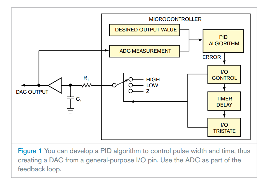
Few microcontrollers include a DAC. Although you can easily find an inexpensive DAC to control from your microcontroller, you can use unused peripherals instead of adding parts. Fortunately, you can convert a microcontroller's ADC channel along with a GPIO (general-purpose input/output) pin into a DAC. You can make a DAC by charging a capacitor to an analog level by driving it high. You can also discharge the capacitor by driving it low, or you can hold its voltage by tristating it (
Figure 1). At first glance, this approach seems like a crude way to make a DAC. The technique becomes more plausible, however, when you use a PID (proportional-integral-derivative) algorithm and monitor the voltage with the microcontroller's ADC.
You can use the PID algorithm to compare the output voltage with the desired value and calculate the error. If the error value is zero, then the I/O control block tristates the GPIO pin. If the error signal is positive or negative, then the I/O control block turns the I/O pin to a high state to charge the capacitor or to a low state to discharge it. Your microcontroller code should load the error value into a timer to generate a timed pulse. The error-value sign determines the charge/discharge cycle, and its magnitude determines the duration of the pulse. Once the cycle is complete, you can set the I/O pin to a tristate mode, which holds the value. The algorithm can run as a software loop. You can call it based on another timer interrupt. To minimize the response time, make sure that this algorithm runs at the desired output value slightly longer than 2.2RC. You need the extra time to completely charge or discharge the capacitor through resistor R1.
The DAC's resolution depends on several factors, the foremost of which is ADC resolution. The DAC's resolution never exceeds that of the ADC. Variable selection and timer resolution also affect DAC resolution. To implement a 10-bit DAC, you need a 16-bit timer and 16-bit variables for the PID algorithm. You can use a lower-resolution timer, but you must more frequently call the algorithm. That action results in longer settling times and higher CPU usage.
By adjusting the algorithm's PID variables, you can achieve surprisingly good output settling times with little change to the DAC's output after settling. The stability of the ADC's voltage reference limits temperature stability. Neither the temperature stability of R1 and C1 nor the leakage of C1 has an adverse effect on the DAC's stability. The selection of R1 and C1 depends on the application, and you should select them based on settling time. For relatively slow-acting DACs, you can increase the update rate by running the algorithm faster than the 2.2RC period and using an 8-bit timer. To buffer the DAC output, use an op amp as a voltage follower or use a common emitter follower. You can use a noninverting amplifier to amplify the output and feed just a portion of it to the ADC through a voltage divider.
- Make a DAC with a microcontroller's PWM timer
http://www.edn.com/design/analog/4337128/Make-a-DAC-with-a-microcontroller-s-PWM-timer Many embedded ...
- 基于STM32Cube的ADC模数采样设计
1.背景 此实验建立在STM32F429核心板基础上,对于深刻了解STM32Cube使用具有深刻意义.利用DMA进行ADC采样,具有速度快,极大减少CPU消耗的优势,对于数据采集系统具 ...
- Micropython TPYBoard ADC的使用方法
基本用法 import pybadc = pyb.ADC(Pin('Y11')) # create an analog object from a pinadc = pyb.ADC(pyb.Pin.b ...
- 【STM32】PWM DAC基本原理(实验:PWM实现DAC)
虽然STM32F103ZET6具有内部DAC,但是也仅仅只有两条DAC通道,并且STM32还有其他的很多型号是没有DAC的.通常情况下,采用专用的D/A芯片来实现,但是这样就会带来成本的增加. 不过S ...
- 玩转X-CTR100 l STM32F4 l DAC数字模拟转换
我造轮子,你造车,创客一起造起来!塔克创新资讯[塔克社区 www.xtark.cn ][塔克博客 www.cnblogs.com/xtark/ ] 本文介绍X-CTR100控制器 DAC接口 ...
- STC 单片机ADC实现原理
模数转换器原理 数模转换器( analog to digitI converter,ADC),简称为A/D,ADC是链接模拟世界和数字世界的桥梁.它用于将连续的模拟信号转换为数字形式离散信号.典型的, ...
- quick start guide for XMEGA ADC
This is the quick start guide for the Analog to Digital Converter (ADC), with step-by-step instructi ...
- AVR单片机教程——DAC
本文隶属于AVR单片机教程系列. 单片机的应用场景时常涉及到模拟信号.我们已经会使用ADC把模拟信号转换成数字信号,本讲中我们要学习使用DAC把数字信号转换成模拟信号.我们还将搭建一个简单的功率放 ...
- LPC43xx SGPIO Experimentation
LPC4350 SGPIO Experimentation The NXP LPC43xx microcontrollers have an interesting, programmable ser ...
随机推荐
- 2017 ACM - ICPC Asia Ho Chi Minh City Regional Contest
2017 ACM - ICPC Asia Ho Chi Minh City Regional Contest A - Arranging Wine 题目描述:有\(R\)个红箱和\(W\)个白箱,将这 ...
- python不可以打印.doc文件
[背景] 需求: 打印word文件 模块: python-docx [问题] 传递xxx.doc文件给python脚本,执行后,控制台没有内容输出 经查询后了解到,大致理由: doc是早一代的word ...
- centos7下vi的用法
vi编辑器是所有Unix及Linux系统下标准的编辑器,它的强大不逊色于任何最新的文本编辑器,这里只是简单地介绍一下它的用法和一小部分指令.由于对Unix及Linux系统的任何版本,vi编辑器是完全相 ...
- 4、GitLab 创建、删除、修改项目
一.gitLab创建项目 1.创建用户组 2.填写组信息后单击“Create group” 其中:“Group path”将显示在git路径中 3.选择需要加入该组的“用户”和“角色”后点击“Add ...
- Delphi 通过字符串实例化类
通过字符串创建窗体类对象 1.需要在程序初始化的时候将类注册,注册到对象 RegGroups:(TRegGroups)中,以便查找. 注册类使用的函数:RegisterClass ,窗体初始化操作放在 ...
- (二) Mysql 数据类型简介
第一节:整数类型.浮点数类型和定点数类型 1,整数类型 2,浮点数类型和定点数类型 M 表示:数据的总长度(不包括小数点): D 表示:小数位: 例如 decimal(5,2) 123.45 ...
- centos7 lvs+keepalived nat模式
1.架构图 3.地址规划 主机名 内网ip 外网ip lvs-master 192.168.137.111(仅主机)eth1 172.16.76.111(桥接)eth0 lvs-slave 192 ...
- JS函数学习
=============数学函数========== 1.Math.random()为取随机数0~1之间的:0可以取到,1取不到 alert(Math.random()); 2.Math.PI为3. ...
- PhpStorm设置函数注释模板
*设置位置:"Settings"->"file templates"; 如下图,设置头部注释.类注释以及函数注释,时间.用户名.文件名称等随机改变的属性, ...
- Templated Helper Methods
1.Model 2.HomeController 3.CreatePerson.cshtml 禁用了客户端验证 4.Using Templated Helper Methods Editor 和 Ed ...
