Make a DAC with a microcontroller's PWM timer
http://www.edn.com/design/analog/4337128/Make-a-DAC-with-a-microcontroller-s-PWM-timer
Many embedded-microcontroller applications require generation of analog signals. An integrated or stand-alone DAC fills the role. However, you can often use PWM signals for generating the required analog signals. You can use PWM signals to create both dc and ac analog signals. This Design Idea shows how to use a PWM timer to simultaneously create a sinusoid, a ramp, and a dc voltage. A PWM signal is a digital signal with fixed frequency but varying duty cycle. If the duty cycle of the PWM signal varies with time and you filter the PWM signal, the output of the filter is an analog signal (Figure 1).

If you build a PWM DAC in this manner, its resolution is equivalent to the resolution of the PWM signal you use to create the DAC. The PWM output signal requires a frequency that is equivalent to the update rate of the DAC, because each change in PWM duty cycle is the equivalent of one DAC sample. The frequency the PWM timer requires depends on the required PWM signal frequency and the desired resolution. The required frequency is FCLOCK=FPWM×2n, where FCLOCK is the required PWM-timer frequency, FPWM is the PWM-signal frequency, and n is the desired DAC resolution in bits.

depicts a circuit that delivers a 250-Hz sine wave, a 125-Hz ramp, and a dc signal. The desired sampling rate is 8 kHz (32 samples for each sine-wave cycle (16× oversampled), and 64 samples for each ramp cycle (32× oversampled)). These figures result in a required PWM-signal frequency of 8 kHz and a required PWM clock frequency of 2.048 MHz. It is usually best for the PWM signal frequency to be much higher than the desired bandwidth of the signals to be produced. Generally, the higher the PWM frequency, the lower the order of filter required and the easier it is to build a suitable filter. This design uses Timer B of the MSP430 in 16-bit mode and in "up" mode, in which the counter counts up to the contents of capture/compare register 0 (CCR0) and then restarts at zero. CCR0 is loaded with 255, thereby giving the counter an effective 8-bit length. You can find this register and others in a DAC demonstration program for the MSP430 microcontroller. Click here to download the program.
CCR1 and output TB1 produce the sine wave. CCR2 and TB2 generate the ramp, and CCR3 and TB3 yield the dc value. For each output, the output mode is the reset/set mode. In this mode, each output resets when the counter reaches the respective CCRx value and sets when the counter reaches the CCR0 value. This scheme provides positive pulses equivalent to the value in CCRx on each respective output. If you use the timer in 8-bit mode, the reset/set output mode is unavailable for the PWM outputs because the reset/set mode requires CCR0. The timer's clock rate is 2.048 MHz. Figure 3

shows the sine and ramp waveforms. The sine wave in this example uses 32 samples per cycle. The sample values are in a table at the beginning of the program. A pointer points to the next value in the sine table, so that, at the end of each PWM cycle, the new value of the sine wave is written to the capture/compare register of the PWM timer.
The ramp in this example does not require a table of data values. Rather, the ramp simply increments the duty cycle for each cycle of the PWM signal until it reaches the maximum and then starts over at the minimum duty cycle. This gradual increase in PWM-signal duty cycle results in a ramp voltage when the signal passes through a filter. You control the dc level by simply setting and not changing the value of the PWM-signal duty cycle. The dc level is directly proportional to the duty cycle of the PWM signal. Figure 2 shows the reconstruction filters used for each signal in this example. The filter for the ac signals is a simple two-pole, stacked-RC filter, which is simple and has no active components. This type of filter necessitates a higher sampling rate than would be required if the filter had a higher order. With the type of filter shown in Figure 2, you should use at least a 16× oversampling rate.
The filter yields its best response when R2>>R1. Also, setting the cutoff frequency too close to the bandwidth edge causes a fair amount of attenuation. To reduce the amount of attenuation in the filter, set the cutoff frequency above the bandwidth edge but much lower than the frequency of the PWM signal. The filter for the dc value serves for charge storage rather than ac-signal filtering. Therefore, it uses a simple, single-pole RC filter. Figure 4
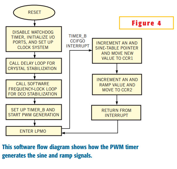
shows the software flow for the DAC. After a reset, the routine stops the watchdog timer, configures the output ports, and sets up the clock system. Next, the software calls a delay to allow the 32,768-Hz crystal to stabilize to calibrate the DCO (digitally controlled oscillator).
Next, the routine calls the calibration routine to set the operating frequency to 2.048 MHz. After the DCO calibration, the program sets up Timer_B, CCR1 and CCR2 for PWM generation and then starts the timer. Finally, the MSP430 goes into low-power mode 0 (LPM0) to conserve power. The CPU wakes up to handle each CCIFG0 interrupt from the PWM timer and then re-enters LPM0. (See references 1, 2, and 3 for more information on the DCO and the MSP430 family.)
Make a DAC with a microcontroller's PWM timer的更多相关文章
- 【STM32】PWM DAC基本原理(实验:PWM实现DAC)
虽然STM32F103ZET6具有内部DAC,但是也仅仅只有两条DAC通道,并且STM32还有其他的很多型号是没有DAC的.通常情况下,采用专用的D/A芯片来实现,但是这样就会带来成本的增加. 不过S ...
- Create a DAC from a microcontroller's ADC
Few microcontrollers include a DAC. Although you can easily find an inexpensive DAC to control from ...
- Cortex-A9 PWM Timer
PWM定时器 4412时钟为我们提供了PWM定时器,在4412中共有5个32位的定时器,这些定时器可发送中断信号给ARM子系统.另外,定时器0.1.2.3包含了脉冲宽度调制(PWM),并 ...
- PWM DAC vs. Standalone
http://analogtalk.com/?p=534 http://analogtalk.com/?p=551 Posted by AnalogAdvocate on April 09, 2010 ...
- PWM DAC Low Pass Filtering
[TI博客大赛][原创]LM3S811之基于PWM的DAC http://bbs.ednchina.com/BLOG_ARTICLE_3005301.HTM http://www.fpga4fun.c ...
- how to generate an analog output from a in-built pwm of Atmega 32AVR microcontrloller?
how to generate an analog output from a in-built pwm of Atmega 32AVR microcontrloller? you need a re ...
- M451 PWM对照数据手册分析
PWM_T Struct Reference Control Register » Pulse Width Modulation Controller(PWM) typedef struct { ...
- 说说M451例程之PWM的寄存器讲解
M451提供了两路PWM发生器.每路PWM支持6通道PWM输出或输入捕捉.有一个12位的预分频器把时钟源分频后输入给16位的计数器,另外还有一个16位的比较器.PWM计数器支持向上,向下,上下计数方式 ...
- 说说M451例程之PWM
/**************************************************************************//** * @file main.c * @ve ...
随机推荐
- mac系统安装redis
1.下载 打开官网:https://redis.io/ Download---Stable---Download3.2.8,下载最新稳定版,这里是3.2.8 2.安装 下载完成后,打开命令行工具,执行 ...
- MFC中CString.Format类详解
在MFC程序中,使用CString来处理字符串是一个很不错的选择.CString既可以处理Unicode标准的字符串,也可以处理ANSI标准的字符串.CString的Format方法给我们进行字符串的 ...
- javascript数组元素的添加、删除与插入以及参数数组的使用
1.数组元素的添加 push方法在数组的尾部添加元素: var colorArray=new Array(); colorArray.push('red','black','yellow'); //这 ...
- redux-saga印象
saga作为redux的中间件,用来处理异步任务. 先收集资料: 贴个文章(2)中的图先: 注意:参考文献(4)是redux-saga作者写的. 参考文章: (1)https://redux-saga ...
- 解决mysql不能远程登入的问题
mysql远程不能登入,问题就在于当时设置的账号只限制本地访问,mysql默认也只是本地访问. 之前的设置: 通过命令行登录管理MySQL服务器(提示输入密码时直接回车): mysql> /us ...
- GMM与EM算法
用EM算法估计GMM模型参数 参考 西瓜书 再看下算法流程
- bzoj 3926 转换+广义后缀自动机
思路:重点在于叶子节点只有20个,我们把叶子节点提到根,把20个trie图插入后缀自动机,然后就是算有多少个本质不同的字串. #include<bits/stdc++.h> #define ...
- js根据IP跳转
<script language="javascript" type="text/javascript" src="http://int.dpo ...
- xshell连接linux,切换焦点,自动执行ctrl+c
这几天发现 xshell 连接 linux 的时候,无缘无故的执行了 ctrl+c,导致 执行界面 终端,比方说 ,hbase shell 执行窗口命令 ,每次切换 窗口焦点之后,就终止了.百度后 发 ...
- Ext.example.msg()应用
①需要在开发包中包含文件夹example/shared中的example.js和example.css两个文件即可. ②在html文件中引入: <script src="../extj ...