Serial Wire Viewer (SWV)
Being able to display values for counters, sensors and other debugging information is an important part of software development for microcontrollers. Writing software for PCs is much easier in this regard as there is already a monitor to which you could print values etc. to simply the development process. For microcontrollers the obvious choice is to use a LCD connected to some of the microcontroller's port pins and with the use of the proper LCD library one can then print these values to the LCD. This does however increase your development cost as the LCDs will normally cost in the region of R100 - R300 and often supporting interfacing circuitry will have to be build for the correct operation of the LCD. With the SMT32 microcontrollers, there are fortunately other options:
- Use the in-circuit debugger. This is a very powerful feature, but requires a bit of learning.
- Use the UART/USART module. By connecting the TX and RX pins through an appropriate voltage level converter to a PC's COM port, one can print values to a Serial Monitor (e.g. Termite, Hyperterminal, etc.) application on the PC, and even get values from the PC.
- Use a Virtual COM Port (VCP). Provides the same functionality as the UART/USART, but does not require the use of a voltage level converter and is plugged into a USB port which simulates a COM port. This does require appropriate drivers on the PC and also on the microcontroller. Furthermore the microcontroller must have an USB module.
- Use the Serial Wire Output (SWO). This feature will allow one to print values to a Serial Wire Viewer (SWV) via the SWO pin on the mictrontoller and the in-circuit programmer with no additional hardware, cables or drivers.
This section will describe how to use and set up the Serial Wire Viewer for the STM32F3-Discovery. The other options are also explained in seperate sections.
Here are the topics to cover for using the SWV:
ST-Link/V2
The STM32F3-Discovery includes a built-in ST-Link/V2 in-circuit programmer and debugger which is used in the Keil MDK (uVision) to download the source code to the ARM microcontroller. This will also provide the interface through which the ARM microcontroller will send a value to be printed to the SWV. The following is required:
- Update the ST-Link Utility to the latest version (currently it is v3.3.0) at the following link: http://www.st.com/web/en/catalog/tools/PF258168
- Update the ST-Link/V2 programmer's firware using the ST-Link Utility.
- Disconnect the USB cable.
- Remove the two jumpers (CN4) on the board.
- Connect the USB cable
- Open the ST-Link Utility
- Select ST-Link → Firmware update
- Click Device Connect
- Click Yes
- Close the update window and the ST-Link Utility
- Disconnect the USB cable
- Replace the two jumpers (CN4)
STM32F3-Discovery board
By default the SWO pin of the STM32F303VCT6 microcontroller is is NOT linked to the ST-Link/V2 programmer. To create the link, we can do the following:
- Connect a wire link between PB3 and pin6 of the SWD connector (CN3)
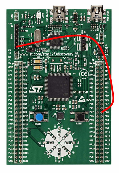
OR
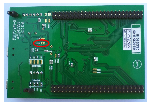
- Close the solder bridge (jumper) SB10 at the botom of the board by soldering the two pads together. This is a more permanent option, but can be reversed by carefully de-soldering the two pads and making sure with a multi-meter that they are indeed seperated.
*** IMPORTANT NOTICE ***
Please note that PB3 can now not be used as a normal GPIO pin, until the above changes are reversed.
Configuring a Keil project
Assuming that you have an already working project which is correctly set up for Flash programming and debugging, do the following to add the SWV capability (you can use the example source files at the top of this page):
- Open the project in Keil MDK (uVision)
- Right-click on the project name in the Project window and select Options for target ...
- In the Debug tab, select Settings
- In the Trace tab, make the following selections:
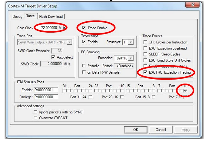
- Click OK
- Close the Options for Target dialog
- Compile and Flash Download (program)/Debug as usual.
Add code
The standard printf statement makes use of the fputc function. We need to retarget the fputc function to use the Trace on ITM Stimulus Port 0. To do this, simply add the following code to your programs that uses the SWV:
int fputc(int ch, FILE *f)
{
return(ITM_SendChar(ch));
}
The fputc function could actually be retargetted to print to the SWV and to the USART (or even an LCD) at the same time, e.g:
int fputc(int ch, FILE *f)
{
/* the USART */
UART4->TDR = (ch & (uint16_t)0x01FF);
while ((UART4->ISR & USART_FLAG_TXE) == (uint16_t) RESET);
/* the SWV */
return(ITM_SendChar(ch));
}
Using the Serial Wire Viewer (SWV)
Once all the previous topics were done, do the following to use the SWV:
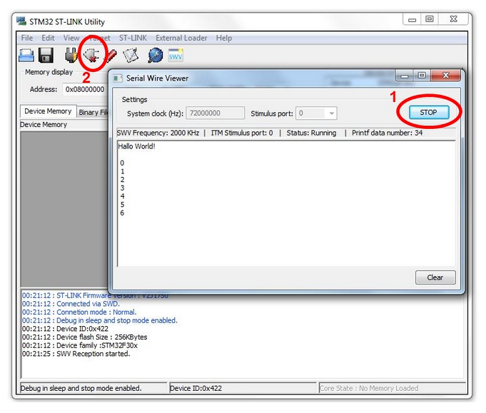
- Open the STM32 ST-Link Utility
- Select ST-LINK → Printf via SWO viewer
- Set the System clock to 72000000
- Set the Stimulus port to 0
- Click Start
The SWV is now ready for receiving characters and values from the printf statements in the source code. It has now grabbed the handle and interface to the ST-Link/V2 programmer and Flash Downloading and Debuggin in uVision will now not be possible. To reprogram changes or new source code to the STM32F3-Discovery board, you will have to:
- Click STOP in the SWV window
- Click the Disconnect button
The handle and interface to the ST-Link/V2 programmer is now released and can be used in Keil uVision again to program the device as usual.
Clicking Start in the SWV window will now reset the board and start the serial connection again.
/*#############################################################

 File Name       : ex1_SWOViewer_HelloWorld.c

 Author          : Grant Phillips

 Date Modified   : 13/05/2014

 Compiler        : Keil ARM-MDK (uVision V4.70.0.0)

 Tested On       : STM32F3-Discovery

 Description     : Example program that uses Trace Events to

 write "Hello World!" via the ST-Link programmer

 to the ST-Link Utility's SWO Viewer and then

 display a count from 0 to 255 repeatedly. The

 count value is also written to the 8 USER LEDs.

 Visit the following link for more information

 regarding the SWO Viewer:

 http://controlsoft.nmmu.ac.za/STM32F3-Discovery

 -Board/Example-programs/SWO-Viewer

 Requirements    : * STM32F3-Discovery Board

 Circuit         : * A wire link between PB3 and pin6 of the SWD

 connector (CN3)

 OR

 solder the solder bridge SB10 closed underneath

 the board

 Note that PB3 will now not be available as a

 normal GPIO pin.

 See the STM32F3-Discovery User Manual (UM1570) for the block

 diagram of the STM32F303VCT6 processor (p13), a summary of

 the GPIO connections (p21-29) and the schematic diagram (p31-34)

 ##############################################################*/

/* #includes -------------------------------------------------*/

#include "main.h"

//main library to include for device drivers, peripheral drivers, etc.

/* #defines --------------------------------------------------*/

/* #function prototypes --------------------------------------*/

void InitLEDs( void ); //prototype for the user function to initialize the USER LEDs

/* #global variables -----------------------------------------*/

// Unused global variables that have to be included to ensure correct compiling */

// ###### DO NOT CHANGE ######

// ===============================================================================

__IO uint32_t TimingDelay = ;                    //used with the Delay function

__IO uint8_t DataReady = ;

__IO uint32_t USBConnectTimeOut = ;

__IO uint32_t UserButtonPressed = ;

__IO uint8_t PrevXferComplete = ;

// ===============================================================================

int main( void )

{

  uint8_t count = ;    //8-bit integer variable to hold the count value (0-255)

  RCC_ClocksTypeDef RCC_Clocks; //structure used for setting up the SysTick Interrupt

  /* Set the SysTick Interrupt to occur every 1ms) */

  RCC_GetClocksFreq( &RCC_Clocks );

  if ( SysTick_Config( RCC_Clocks.HCLK_Frequency /  ) )

    while (  )

      ; //will end up in this infinite loop if there was an error with Systick_Config

  InitLEDs( ); //initialize the USER LEDs for this application

  //print a message to the SWO Viewer (make sure the fputc function is

  //retargeted as shown by the fputc function just after main()

  printf( "Hallo World!\n" );

  /* Main program loop */

  while (  )

  {

    printf( "\n%2X", count );       //print a newline and integer value (in HEX)

    GPIO_Write( GPIOE, count <<  );

    //shift the value 8 spaces to the left,

    //because we are writing it to the high byte (PE15 - PE8)

    count = count + ;

    Delay(  );

  }

}

/*

 Retarget the C library printf function to the SWO Viewer.

 Overwrites int fputc(int ch, FILE *f) function used by printf.

 */

int fputc( int ch, FILE *f )

{

  return ( ITM_SendChar( ch ) );

}

void InitLEDs( void )

{

  GPIO_InitTypeDef GPIO_InitStructure; //structure used for setting up a GPIO port

  /* GPIOE Periph clock enable */

  RCC_AHBPeriphClockCmd( RCC_AHBPeriph_GPIOE, ENABLE );

  /* Configure PE15 - PE8 in output pushpull mode */

  GPIO_InitStructure.GPIO_Pin = GPIO_Pin_15 | GPIO_Pin_14 | GPIO_Pin_13

    | GPIO_Pin_12 | GPIO_Pin_11 | GPIO_Pin_10 | GPIO_Pin_9 | GPIO_Pin_8;

  //which pins to setup, seperated by |

  GPIO_InitStructure.GPIO_Mode = GPIO_Mode_OUT;

  GPIO_InitStructure.GPIO_OType = GPIO_OType_PP;

  GPIO_InitStructure.GPIO_Speed = GPIO_Speed_50MHz;

  GPIO_InitStructure.GPIO_PuPd = GPIO_PuPd_NOPULL;

  GPIO_Init( GPIOE, &GPIO_InitStructure );

}

// -------------------------------------------------------------------------------

// Function to insert a timing delay of nTime

// ###### DO NOT CHANGE ######

void Delay(__IO uint32_t nTime)

{

  TimingDelay = nTime;

  while(TimingDelay != );

}

// Function to Decrement the TimingDelay variable.

// ###### DO NOT CHANGE ######

void TimingDelay_Decrement( void )

{

  if ( TimingDelay != 0x00 )

  {

    TimingDelay--;

  }

}

// Unused functions that have to be included to ensure correct compiling

// ###### DO NOT CHANGE ######

// =======================================================================

uint32_t L3GD20_TIMEOUT_UserCallback( void )

{

  return ;

}

uint32_t LSM303DLHC_TIMEOUT_UserCallback( void )

{

  return ;

}

// =======================================================================
Serial Wire Viewer (SWV)的更多相关文章
- Serial Wire Debug (SWD) Interface -- PSoc5
PSoC 5 supports programming through the serial wire debug (SWD) interface. There are two signals in ...
- SW-DP (Serial Wire Debug Port) Analyzer plugin for the Saleae Logic
SW-DP (Serial Wire Debug Port) Analyzer plugin for the Saleae Logic The SW-DP protocol is described ...
- Programming Internal Flash Over the Serial Wire Debug <SWD> Interface -- EFM32
1 Debug Interface Overview 1.1 Serial Wire Debug Serial Wire Debug (SWD) is a two-wire protocol for ...
- Serial Wire Debugging the STM32 via the Bus Pirate
Serial Wire Debugging the STM32 via the Bus Pirate 2 October 2010 Step 1 - The Bus Pirate Step 2 - D ...
- Implementation of Serial Wire JTAG flash programming in ARM Cortex M3 Processors
Implementation of Serial Wire JTAG flash programming in ARM Cortex M3 Processors The goal of the pro ...
- Introduction to Cortex Serial Wire Debugging
Serial Wire Debug (SWD) provides a debug port for severely pin limited packages, often the case for ...
- windows下STM32开发环境的搭建
一.概述 1.说明 笔者已经写了一篇Linux下STM32开发环境的搭建 ,这两篇文章的最区别在于开发环境所处的系统平台不一样,而其实这个区别对于开发环境的搭建其实影响不大,制作局部上的操作上发生了改 ...
- Keil debugging techniques and alternative printf (SWO function)
One of the basic needs of the embedded software development through the terminal to output debugging ...
- CoreSight™ Technology
ARM Cortex-M processor-based devices use the ARM CoreSight technology which introduces powerful new ...
随机推荐
- jquery-扩展
jQuery扩展三种方式:$.extend,$.fn.extend,外部文件. 1)jQuery.extend(object) 调用 $.方法 2)jQuery.fn.extend(object) ...
- maven dependencies 报错
maven配置的环境变量有问题: 用最新的maven替换系统默认的setting.xml文件即可
- Codeforces 219C Color Stripe(思维+字符串)
题目链接:http://codeforces.com/problemset/problem/219/C 题目大意: 给出一个字符串,只包含k种字符,问最少修改多少个字符(不增长新的种类)能够得到一个新 ...
- Ubuntu 下 vi 输入方向键会变成 ABCD 的解决方法
Ubuntu 下 vi 输入方向键会变成 ABCD,这是 Ubuntu 预装的是 vim tiny 版本,安装 vim full 版本即可解决. 先卸载vim-tiny: $ sudo apt-get ...
- poj 1797 一条路径中的最小边 再找出最大的
Sample Input 1 // T3 3// n m1 2 3//u v w1 3 42 3 5Sample Output Scenario #1:4 # include <iostream ...
- http://blog.csdn.net/five3/article/details/7181521
首先来了解什么是multipart/form-data请求: 根据http/1.1 rfc 2616的协议规定,我们的请求方式只有OPTIONS.GET.HEAD.POST.PUT.DELETE.TR ...
- WebSocket原理说明
WebSocket原理说明 众所周知,Web应用的通信过程通常是客户端通过浏览器发出一个请求,服务器端接收请求后进行处理并返回结果给客户端,客户端浏览器将信息呈现.这种机制对于信息变化不是特别频繁的应 ...
- JSR教程2——Spring MVC数据校验与国际化
SpringMVC数据校验采用JSR-303校验. • Spring4.0拥有自己独立的数据校验框架,同时支持JSR303标准的校验框架. • Spring在进行数据绑定时,可同时调用校验框架完成数据 ...
- c#double类型保留百分号后两位,且禁止四舍五入的方法
double percent = Convert.ToDouble(50002.3) / Convert.ToDouble(50002.5) - 0.00005; string result = pe ...
- CMU-15445 LAB1:Extendible Hash Table, LRU, BUFFER POOL MANAGER
概述 最近又开了一个新坑,CMU的15445,这是一门介绍数据库的课程.我follow的是2018年的课程,因为2018年官方停止了对外开放实验源码,所以我用的2017年的实验,但是问题不大,内容基本 ...