Transparency Tutorial with C# - Part 1
- Download demo project - 4 Kb
- Download source - 6 Kb
- Download demo project - 5 Kb
- Download source - 6 Kb
- Download demo project - 4 Kb
- Download source - 8 Kb
- Download demo project - 5 Kb
- Download source - 9 Kb
- Download demo project - 5 Kb
- Download source - 8 Kb
Introduction
I decided to write these tutorials after I realized that I didn’t really understand how C# handled transparency. I was doing some alpha blending and the resulting colors were not what I expected. So I built a tool, AlphaBlender Figure 1, to show a Venn diagram
of the colors mixed like in standard color theory texts and I was further puzzled that the tool produced an image unlike any I’d seen in school.
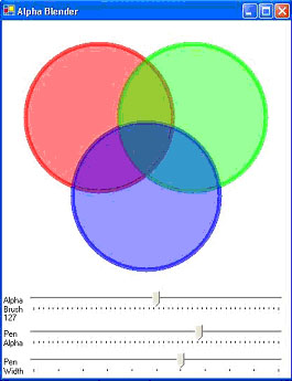
Figure 1 AlphaBlender demo application
Figure 2 shows what I got versus what I expected.
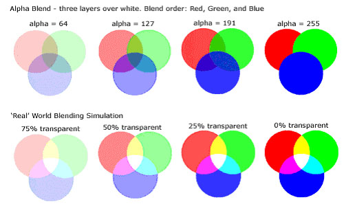
Figure2, Alpha blend versus my expectations of ‘real’ blended colors
Well… nobody told me that alpha blending was supposed to be like my expectations; in fact, I am frequently surprised at how little anything works like I first expect it too. So I decided to write these tutorials to help me understand what’s really going on
with transparency in C#.
In each of these tutorials, we consider the ‘what’ before the ‘how’-- a discussion is presented of the concepts behind the code, and then at the end, we look at the code behind the concepts. In the code section, I’ll introduce each relevant new element of GDI+
as it occurs, and I won’t mention it again if it reoccurs in later code. This should help with redundancy and get the elementary stuff over with quickly.
Also a word of caution: I’m no C# guru. I’ve written the demonstration code to illustrate the transparency concepts, not to demonstrate good programming practice. I encourage any and all to send me comments on my coding practices and how I might improve them.
The Concepts
What Is Color?
Color is a human thing. It is defined by our ability to perceive a narrow band of the electromagnetic spectrum that we call visible light. Our eyes have ’rod’ cells that sense variations in black and white, and we have three types of cone cells, one each for
red, green and blue.
We can simulate our perception of color by mixing red, green, and blue, which is what a computer monitor does. This brings us to the natural use of these components to create colors in C#, where a color is a 32-bit structure of four bytes for Alpha, Red, Green,
and Blue
Alpha is a transparency parameter that defines how much of the existing display color pixel that should ‘show through’ the new color.
Visualization Tools
I propose that if a picture is worth a thousand words, then a demo program is worth a ten thousand. The following demonstrations show some things about transparency use in C#.
I wrote ColorMaker, Figure 3, to show the effect of varying each of the color structure parameters. The color is created over a gradient, black to white, to illustrate how the Alpha value affects the ‘show through’ of the background color

Figure 3, ColorMaker demo application
Next I wrote WhatColorIsIt, Figure 4, to show the color parameters for any pixel on the screen. (This demo is based on Charles Petzold’s WhatColor example from his C# book).
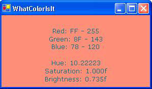
Figure 4, WhatColorIsIt demo application
I combined what I learned with these two programs and wrote Spectrum, Figure 5, which simulates the color spectrum of visible light and allows the user to read the color parameters.
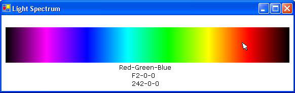
Figure 5 Light spectrum simulation demo application
Transparency
I started this tutorial because I didn’t understand how alpha blending actually worked. Figure 1 shows what I was getting versus what I was expecting, and it also shows fairly obviously what is really going on. Alpha blending does not work like blending light;
it works like stacking glass filters.
If you take a red, green, and blue glass filters and lay them on a background, you would get an effect like what we see in the demo. Filters with 50% transparency should look like the demo with alpha set to 127.
Here’s the alpha blend algorithm:
displayColor = sourceColor×alpha / 255 + backgroundColor×(255 – alpha) / 255
I did some calculations starting with an opaque white background to see what this gives
Add a 50% transparent red pixel over an opaque white pixel:
sourceColor(127,255,0,0) ( Red, 50% transparent)
background Color(255,255,255,255) (Opaque white)
 Collapse | Copy
Code
displayColor Red = ( 255 * 127/255) + (255)*(255 – 127)/255 =

255;

displayColor Green = (0 * 127/255) + (255)*(255 – 127)/255 =

127;

displayColor Blue = (0 * 127/255) + (255)*(255 – 127)/255 =

127;
Resulting Color (127,255,127,127)
Add a 50% transparent green pixel over the results:
sourceColor(127,0,255,0) ( Green, 50% transparent)
backgroundColor(127,255,127,127)
Collapse | CopyCode
displayColor Red = (0 * 127/255) + (255)*(255 – 127)/255 =

127;

displayColor Green = (255 * 127/255) + (127)*(255 – 127)/255 =

192;

displayColor Blue = (0 * 127/255) + (127)*(255 – 127)/255 =

65;
Resulting Color (127,127,192,64)
Add a 50% transparent blue pixel over the results:
sourceColor(127,0,0,255) ( Blue, 50% transparent)
background Color(127,127,192,64)
Collapse | CopyCode
displayColor Red = (0 * 127/255) + (127)*(255 – 127)/255 =

64;

displayColor Green = (0 * 127/255) + (192)*(255 – 127)/255 =

96;

displayColor Blue = (255 * 127/255) + (64)*(255 – 127)/255 = 159;
Resulting Color (127,64,96,159)
Compare the ‘real’ world to the GDI+ world with 50% transparent colors: ‘Real World’ GDI+ World
Red over white (255,0,0) - Pink. (255,0,0) - Pink
Green over results (255,255,0) - Yellow (127,192,64) – Light Olive?
Blue over result (255,255,255) - White. (64,96,159) – Dark Slate Blue?
I did the same calculations starting over opaque black and got:
Red over black (127,0,0) – Med. Red (127,0,0) – Med. Red
Green over results (127,127,0) – Med. Yellow (64,127,0) – Dark Olive?
Blue over results (127127,0) – Med. Gray (32,64,127) – Gray Navy?
Conclusion: Alpha blending simulates real world transparency for one layer only.
I wrote a tool, Alpha Demonstrator Figure 6, to show the effect of ‘stacking’ order and background color to further illustrate what’s really going on. You can change the stacking order and background color in the demo to view each stacking and background color
permutation.
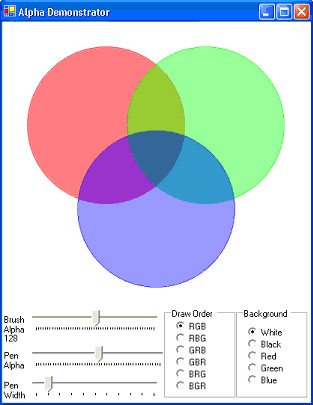
Figure 6, Alpha Demonstrator
To wind things up for this tutorial, I wrote Color Demo, Figure 7, which shows additive and subtractive color and effects of various backgrounds, the way I think they should look to simulate the ‘real’ world.

Figure 7 Color Demo illustrates additive and subtractive color theory
The Code
Note on flicker-free drawing
Some of these tutorial demos push the systems resources and flicker like crazy using ‘standard’ C# coding practices. There are many ways to prevent flicker and I present one way to use a double buffering technique to get fairly flicker free drawing. I say ‘fairly’
because Windows© will draw your image buffer to the screen when it damn well pleases. It would be best to put your buffer into screen memory during the CRT’s vertical blanking interval when nothing is being written to the screen (I’m not sure if this is true
for LCD’s). If Windows© is in the process of writing your image in memory as the CRT ‘paints’ the screen through the memory you are using, the loaded part will show, but the rest won’t since it hasn’t been loaded yet. Windows© finishes loading and on the next
screen painting cycle the full image shows up. This causes a kind of flicker called ‘tear’ and I know of no way to prevent this in GDI+. In DirectDraw you would load your buffered image during the vertical blanking interval and avoid tear. That said, the double
buffering used here prevents most of the flicker that you’d see if you don’t use double buffering and yields results that I can live with.
First you set the style using the Control.SetStyle method for setting flags that categorize supported behavior. The
flags are listed in the ControlStyles enumeration. We will use three:
AllPaintingInWmPaint– the control will ignore theWM_ERASEBKGNDmessage
and paint its own background.UserPaint– the control paints itself rather than letting the OS do
the painting. You do not use the form’s Paint event, you instead override the OnPaint method.DoubleBuffer– the drawing is done in a buffer and the buffer is drawn
to the screen.
In your form constructor add the following styles:
Collapse | CopyCode
public Form1()

{

  //

  // Required for Windows Form Designer support

  //

  InitializeComponent();

  //

// TODO: Add any constructor code after InitializeComponent call

  //

  SetStyle(ControlStyles.AllPaintingInWmPaint |

    ControlStyles.UserPaint |

    ControlStyles.DoubleBuffer,

    true);

}
Next you override the OnPaint method and draw the background:
Collapse | CopyCode
protected override void OnPaint(System.Windows.Forms.PaintEventArgs e)

{

// Fill in Background (for efficiency only the area that has been clipped)

e.Graphics.FillRectangle(new SolidBrush(SystemColors.Window),

e.ClipRectangle.X,

e.ClipRectangle.Y,

e.ClipRectangle.Width,

e.ClipRectangle.Height);

  //

// Do your drawing

//

  //

// Make darn sure you dispose of everything that you create

// that is disposable (brushs, pens, bitmaps, etc.). Garbage

// collection will get rid of the stuff eventually, but it is

// real easy to overload the system with lots of paints.

//

}
Color Maker
The ColorMaker, Figure 3, allows the user to use slider controls to set the red, green, blue, and alpha parameters of the color structure and paint the results over a black to white gradient background.
We create a rectangle for the gradient and the color.
Collapse | CopyCode
// Create rectangle

private Rectangle rect = new Rectangle(8, 48, 272, 72);
The user uses scroll bars sets the color elements.
Collapse | CopyCode
private void trackBarRed_Scroll(object sender, System.EventArgs e)

{

  int temp = trackBarRed.Value;

  if(temp>255)temp = 255;

  red = (byte)temp;

  labelRed.Text = "Red: " + red.ToString();

  Refresh();

}
In the OnPaint method we create the gradient box by first creating a gradient brush that will make a black to white horizontal gradient.
Collapse | CopyCode
// Create back box brush

LinearGradientBrush lgBrush =

new LinearGradientBrush(backRectangle,

Color.Black,

Color.White,

LinearGradientMode.Horizontal);
We then draw this box to the screen using the Graphics FillRectangle method.
Collapse | CopyCode
// Create back box fill

e.Graphics.FillRectangle(lgBrush,backRectangle);
Next we create the colorBrush from color elements provided by the slider values.
Collapse | CopyCode
// Create transparent brushes

SolidBrush colorBrush =

new SolidBrush(Color.FromArgb(alpha,red,green,blue));
We then draw the color over the gradient
Collapse | CopyCode
// Create the color box fills

e.Graphics.FillRectangle(colorBrush,rect);
And don’t forget to clean up.
Collapse | CopyCode
// Dispose now to conserve system resources

lgBrush.Dispose();

colorBrush.Dispose();
AlphaBlender
This is the demonstration that got me to thinking about all this in the first place. As I said in the beginning, it didn’t behave like I expected, instead it did just what it was supposed to.
AlphaBlender, Figure 1, adds FillEllipse to the prior discussion.
Collapse | CopyCode
// Create circle fills

e.Graphics.FillEllipse(redBrush,redRectangle);

e.Graphics.FillEllipse(greenBrush,greenRectangle);

e.Graphics.FillEllipse(blueBrush,blueRectangle);
WhatColorIsIt
WhatColorIsIt, Figure 4, is derived from WhatColor.cs © 2002 by Charles Petzold, www.charlespetzold.com. It uses COM Interoperability, which allows C# users to access non-GDI+ functions from the Win32 API.
This is hardly a beginner topic, but I’ve included it here because the tool itself is so useful and it gives quick insight in how to expand your C# toolset. Make certain that you dispose of anything you create from a DLL since it is unmanaged and doesn’t get
garbage collected when you close.
At the top of the code we add:
Collapse | CopyCode
using System.Runtime.InteropServices;
In the Form1 class we define the external Win2 functions:
Collapse | CopyCode
[DllImport("gdi32.dll")]

public static extern IntPtr CreateDC(string strDriver,

  string strDevice, string strOutput, IntPtr pData);

[DllImport("gdi32.dll")]

public static extern bool DeleteDC(IntPtr hdc);

[DllImport("gdi32.dll")]

public static extern int GetPixel(IntPtr hdc, int x, int y);
We use the form designer to add a timer. Then we use the properties box to add the Tick event. To this we add our (well, Petzold’s) code.
Collapse | CopyCode
private void timer1_Tick(object sender, System.EventArgs e)

{

// Get the current mouse position (screen coordinates).

Point pt = MousePosition;

// Call the three external functions.

IntPtr hdcScreen = CreateDC("Display", null, null, IntPtr.Zero);

int cr = GetPixel(hdcScreen, pt.X, pt.Y);

DeleteDC(hdcScreen);

// Convert a Win32 COLORREF to a .NET Color object

clr = Color.FromArgb((cr & 0x000000FF),

  (cr & 0x0000FF00) >> 8,

  (cr & 0x00FF0000) >> 16);

// Only invalidate if there's a new color.

if (clr != clrLast)

{

  Invalidate();

}

}
In our OnPaint method we only do something if something has changed:
Collapse | CopyCode
if (clr != clrLast)

{

  clrLast = clr;

…
And, to previously discussed concepts we add DrawString
Collapse | CopyCode
e.Graphics.DrawString("\nRed: " +

clr.R.ToString("X00") +

" - " +

clr.R.ToString() +

…More strings… );
LightSpectrum
To the concepts we’ve looked at so far, LightSpectrum, Figure 5, elaborates on the gradient brush to simulate a full spectrum of visible light. I reuse this code in several subsequent demonstrations, so in a real-world coding situation (this is an unreal-world)
I’d put this stuff in its own class. This, as is, really has nothing to do with transparency, but I use it later as a backcolor for transparency demos.
In the OnPaint method we add a new LinearGradientBrush with
some dummy colors.
Collapse | CopyCode
LinearGradientBrush brBrush =

  new LinearGradientBrush(

  rect, Color.Blue, Color.Red,

  LinearGradientMode.Horizontal);
Then we create a color array for the gradient. This array is based on the assumption that the values used will give a good simulation, and to my eye it does.
Collapse | CopyCode
Color[] clrArray =

{

  Color.FromArgb(255,0,0,0),

  Color.FromArgb(255,128,0,128),

  Color.FromArgb(255,255,0,255),

  Color.FromArgb(255,128,0,255),

  Color.FromArgb(255,0,0,255),

  Color.FromArgb(255,0,128,255),

  Color.FromArgb(255,0,255,255),

  Color.FromArgb(255,0, 255,128),

  Color.FromArgb(255,0,255,0),

  Color.FromArgb(255,128,255,0),

  Color.FromArgb(255,255,255,0),

  Color.FromArgb(255,255,128,0),

  Color.FromArgb(255,255,0,0),

  Color.FromArgb(255,128,0,0),

  Color.FromArgb(255,0,0,0)

};
As with the color array, a points array is created with values that we assume will give use a good continuum in our simulation.
Collapse | CopyCode
float[] posArray =

{

  0.0f,

  1.0f/14.0f,

  2.0f/14.0f,

  3.0f/14.0f,

  4.0f/14.0f,

  5.0f/14.0f,

  6.0f/14.0f,

  7.0f/14.0f,

  8.0f/14.0f,

  9.0f/14.0f,

  10.0f/14.0f,

  11.0f/14.0f,

  12.0f/14.0f,

  13.0f/14.0f,

  1.0f

};
Next we create an instance of the ColorBlend class, which defines color and position arrays used for interpolating color blending in a multicolor gradient
Collapse | CopyCode
ColorBlend colorBlend = new ColorBlend();
We then set the properties.
Collapse | CopyCode
colorBlend.Colors = clrArray;

colorBlend.Positions = posArray;
And next we set the LinearGradientBrush InterpolationColors property to our ColorBlend.
Collapse | CopyCode
// Set interpolationColors property

brBrush.InterpolationColors = colorBlend;
AlphaDemonstrator
I built AlphaDemonstrator, Figure 6, to show more variations on alpha blending as it actually works and contrary to my expectations. No new code concepts are added, so no extra discussion is given.
ColorDemo
I wrote ColoDemo to provide a simulation of how I thought color and transparency should be simulated for the ‘real world’. That is, what do we need to do to get the effect of mixing paints or projecting colored lights?
I hacked around a bit and came up with the following function:
Collapse | CopyCode
private Bitmap trueColorMix(Bitmap bitmap1, Bitmap bitmap2,

  int X, int Y, byte alpha)

{

  Color clrPixel1;

  Color clrPixel2;

  int redMix,greenMix,blueMix;

  for(int i = 0; i < bitmap2.Width; i++)

  {

    for(int j = 0; j < bitmap2.Height; j++)

    {

      clrPixel1 = bitmap1.GetPixel(i+X,j+Y);

      clrPixel2 = bitmap2.GetPixel(i,j);

      redMix = ((int)clrPixel1.R + (int)clrPixel2.R);

      if(redMix > 255) redMix = 255;

      greenMix = ((int)clrPixel1.G + (int)clrPixel2.G);

      if(greenMix > 255) greenMix = 255;

      blueMix = ((int)clrPixel1.B + (int)clrPixel2.B);

      if(blueMix > 255) blueMix = 255;

      bitmap1.SetPixel(i+X,

          j+Y,

          Color.FromArgb(alpha,

          (byte)redMix,

          (byte)greenMix,

          (byte)blueMix));

    }

  }

  return bitmap1;

}
This function receives the background bitmap1, the source bitmap2, the source X and Y locations and alpha for the blend. It iterates through each pixel of bitmap2 that overlays bitmap1, adds each pixel together, limiting the maximum value to 255, then resets
the bitmap1 pixel to the new red, green, and blue values and sets alpha to the given alpha.
This provides a good simulation of additive color over a black background.
But it doesn’t work over white since, for white, bitmap1 starts out with all color values already at 255. Putting color over white, subtractive color, is what printers do, using Cyan, Magenta and Yellow as their primary colors. They also use black, since they
can’t get a good black mixing the colors, calling their system CYMK, where K is the black. In the Color Demo code, all that’s needed to demo subtractive color is to start with a white background and subtract the pixels in bitmap2.
In the next tutorial, we’ll begin with images by looking at the CompositingMode Enumeration and the ColorMatrix, andImageAttributes classes
for making color changes to entire images.
转自:http://www.codeproject.com/Articles/6502/Transparency-Tutorial-with-C-Part
Transparency Tutorial with C# - Part 1的更多相关文章
- Transparency Tutorial with C# - Part 2
Download Compositing Mode demo project - 24 Kb Download Compositing Mode source - 26 Kb Download Com ...
- Transparency Tutorial with C# - Part 3
Download image fade demo - 4 Kb Download image fade source project- 7 Kb Download image fade images ...
- [翻译+山寨]Hangfire Highlighter Tutorial
前言 Hangfire是一个开源且商业免费使用的工具函数库.可以让你非常容易地在ASP.NET应用(也可以不在ASP.NET应用)中执行多种类型的后台任务,而无需自行定制开发和管理基于Windows ...
- Django 1.7 Tutorial 学习笔记
官方教程在这里 : Here 写在前面的废话:)) 以前学习新东西,第一想到的是找本入门教程,按照书上做一遍.现在看了各种网上的入门教程后,我觉得还是看官方Tutorial靠谱.书的弊端一说一大推 本 ...
- thrift 服务端linux C ++ 与客户端 windows python 环境配置(thrift 自带tutorial为例)
关于Thrift文档化的确是做的不好.摸索了很久才终于把跨linux与windows跨C++与python语言的配置成功完成.以下是步骤: 1) Linux下环境配置 ...
- Hive Tutorial(上)(Hive 入门指导)
用户指导 Hive 指导 Hive指导 概念 Hive是什么 Hive不是什么 获得和开始 数据单元 类型系统 内置操作符和方法 语言性能 用法和例子(在<下>里面) 概念 Hive是什么 ...
- Home / Python MySQL Tutorial / Calling MySQL Stored Procedures in Python Calling MySQL Stored Procedures in Python
f you are not familiar with MySQL stored procedures or want to review it as a refresher, you can fol ...
- Using FreeMarker templates (FTL)- Tutorial
Lars Vogel, (c) 2012, 2016 vogella GmbHVersion 1.4,06.10.2016 Table of Contents 1. Introduction to F ...
- Oracle Forms 10g Tutorial Ebook Download - Oracle Forms Blog
A step by step tutorial for Oracle Forms 10g development. This guide is helpful for freshers in Orac ...
随机推荐
- android SQLite使用SQLiteOpenHelper类对数据库进行增删查改
一个简单的例子,当点击按钮时进行相应的操作,效果图如下: 项目代码如下: DatabaseHelper类 package com.example.sqlitedatebasetest; import ...
- Arcgis Desktop 9.3 安装
以下用到的 Crack在我的网盘中有: ref: http://pan.baidu.com/s/1pJJlVBl 密码: p4gk 一,安装 Desktop(依次按照如图安装): 二,配置 1,以上步 ...
- Android自定义扁平化对话框
平时我们开发的大多数的Android.iOS的APP,它们的风格都是拟物化设计.如今Android 4.X.iOS 7.WP8采用的是扁平化设计,可以看出扁平化设计是未来UI设计的趋势.其实扁平化设计 ...
- jquery在不同浏览器获取文件路径出现问题!
<input type="file" name="file" id="file1" src=""/> < ...
- mysql-1862、1820、java.sql.SQLException: Your password has expired. To log in you must change it using a client that supports expired passwords.
之前一直运行的好好的,突然mysql就无法工作了.请求命令后报错误:ERROR 1820 (HY000): You must SET PASSWORD before executing this st ...
- PHP防止SQL注入的方法
[一.在服务器端配置] 安全,PHP代码编写是一方面,PHP的配置更是非常关键. 我们php手手工安装的,php的默认配置文件在 /usr/local/apache2/conf/php.ini,我们最 ...
- DotNET知识点总结三(笔记整合)
使用接口的注意事项: 接口中的成员不能加访问修饰符 接口中的成员不能有任何实现 实现接口的子类必须实现接口的全部成员 一个类可以同时继承一个类并实现多个接口,如果一个子类同时继承了父类A,并实现了接口 ...
- new Date参数问题
new Date支持的参数: MDN: new Date(); new Date(value); new Date(dateString); new Date(year, month, ...
- 简单DOS命令实现局域网Windows远程关机
1秒内重启局域网内计算机名为ppgsvr-pc的用户电脑shutdown -r -m \\ComputerName -t 1 1秒内关闭局域网内ppgsvr用户电脑shutdown -s -m \\C ...
- SQLiteDatabase里面的简单操作数据库的方法
1.使用insert方法插入记录SQLiteDatabase的insert方法的签名为long insert(String table,String nullColumnHack,ContentVal ...