
UML Diagrams Using Graphviz Dot
Introduction
Background
This article is about using the dot tool from the Graphviz package to automatically generate UML diagrams on the fly. We'll take a look at modelling packages, classes, attributes, methods and associations which already covers a fair subset of the class diagrams in UML.
Of course, the information given in this article is only of limited use in situations where you are manually entering the graph description, but the information is highly useful when you're writing a tool which analyzes program structure. So read on if you're writing a piece of software like UMLGraph.
Getting Started
What you need
First of all, you need to have the Graphviz package installed on your computer, head over to the Graphviz website to download a version for your operating system. Windows users can find binary installers there, Linux users should simply use their package manager since graphviz is a common piece of software. For other Unices, you should download and compile the source code.
There aren't many other prerequisites, but it helps if you've got a good example scenario to start with. In this article I'll be using a somewhat contrived and artificial example, but I hope it gets the point through. You might also want to make sure you have the Bitstream Vera family of fonts installed as I will be using these throughout the article.
The so-called "problem"
The example will be based on a small portion of an animal inspired domain. We'll model a simple Animal superclass which will have two subclasses: Dog and Cat. Animal will have some attributes and methods and both Dog and Cat will add another method to the mix.
We'll model an association between Dog and Cat which resembles an arch-enemy relation. This relation will be of an N:M multiplicity. Besides this, the Animal class will be in the default package, while both Dog and Cat are placed in a package called "animal.impl".
So, fire up a text editor and let's type away.
Graphing Basics
General properties
Let's start off by writing the boilerplate for the dot tool:
digraph G {
        fontname = "Bitstream Vera Sans"
        fontsize = 8

        node [
                fontname = "Bitstream Vera Sans"
                fontsize = 8
                shape = "record"
        ]

        edge [
                fontname = "Bitstream Vera Sans"
                fontsize = 8
        ]
Don't worry if you don't get this immediately. The first line tells dot we want to draw a directed graph, or digraph for short. A directed graph is a graph in which all edges point from one node to another node, each edge has a start and end node.
The second and third lines set the font properties for the graph, as you can see the next few lines set the font properties for the default nodes and edges as well. There's one line of interest which isn't covered yet, it's the one defining the shape property for nodes.
We set the shape to record because the record shape allows a node to be separated using bars. As we'll see later on, this is the perfect way to model an UML class diagram.
Modelling the Animal class
Let's model the Animal class, which will have a public "name" and "age" property and a public method called "die()". As I stated earlier, this example is somewhat artificial, but it works. I modelled the Animal class like this:
        Animal [
                label = "{Animal|+ name : string\l+ age : int\l|+ die() : void\l}"
        ]
If you're not familiar with the dot syntax, it will look awkward to you. But let's look at what this class looks like after using dot:
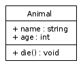
The basic Animal class example generated by dot.
Seeing this should give you an idea about how the dot syntax works.
Why the Animal class looks like this
The label property we've set for the Animal node does a few things:
- The opening and closing curly braces "{" and "}" indicate that we want to create a "record" shape with multiple dividers.
- The pipe characters "|" indicate the dividers, we use one to separate the class name from the attributes and another one to separate the methods from the attributes.
- Putting the "\l" characters after a line of text indicates the line should be aligned to the left side of the shape and that a new line of text should start.
Trying it for yourself
To generate the Animal example yourself, copy and paste the following code in a file called "class.dot":
digraph G {
        fontname = "Bitstream Vera Sans"
        fontsize = 8

        node [
                fontname = "Bitstream Vera Sans"
                fontsize = 8
                shape = "record"
        ]

        edge [
                fontname = "Bitstream Vera Sans"
                fontsize = 8
        ]

        Animal [
                label = "{Animal|+ name : string\l+ age : int\l|+ die() : void\l}"
        ]
}
Now, open a terminal in the directory you've created this file and call the dot tool like this:
dot -T png -o class.png class.dot
This will generate a PNG file with the Animal class model in it. For the rest of the article, I will assume that you can add closing braces yourself, so I won't give you the full code for each example anymore.
Futher Modelling
Creating the Dog and Cat classes
The Dog and Cat classes are actually quite simple once you've seen the Animal class. Add the following lines after the Animal class and before the closing curly brace:
        Dog [
                label = "{Dog||+ bark() : void\l}"
        ]

        Cat [
                label = "{Cat||+ meow() : void\l}"
        ]
If you run dot on the resulting file, you'll see the three classes without any associations or relations between them:
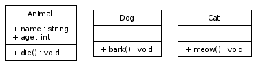
The three classes: Animal, Dog and Cat.
Modelling the subclass relation
Dog and Cat should be subclasses of Animal. Let's add two lines originating from Dog and Cat and ending at the Animal class with an empty arrowhead, UML's way of expresing a subclass relation. Enter the following lines after the Cat declaration, but before the ending curly brace:
        edge [
                arrowhead = "empty"
        ]

        Dog -> Animal
        Cat -> Animal
You can see the arrowhead being set to "empty" in the second line. The lines with "->" in them describe the directed relations. Dog points to Animal, Cat points to Animal: both subclass relationships are defined in those lines. Using dot, the UML diagram now looks like this:
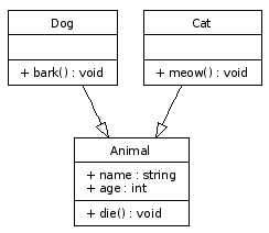
The three classes and the subclass relations are now modelled.
Modelling the "arch-enemy" association
Let's add the N:M relationship between Dog and Cat. I used the following lines in my dot file, enter these after the subclass relation lines but before the closing curly brace:
        edge [
                arrowhead = "none"

                headlabel = "0..*"
                taillabel = "0..*"
        ]

        Dog -> Cat
The second line disables the arrowhead, necessary because association do not exhibit a graphival direction. The "headlabel" and "taillabel" values describe the texts shown at the beginning and end of the edge. In the case of a N:M relation, both of these labels should read "0..*". The last line adds an edge between the Dog and Cat class. After running dot, the result is this:
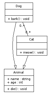
The arch-enemy association between Dog and Cat is now modelled.
Modelling the package
Adding the package to the mix is a bit more complicated, you'll need to add two lines before the declaration of the Dog class:
        subgraph clusterAnimalImpl {
                label = "Package animal.impl"
Add a closing brace "}" just below the Cat class declaration.
The first line tells dot that the coming nodes are to be clustered together in a box. The second line describes the label of the box. The name of the subgraph is very important: only subgraphs having a name starting with "cluster" are drawn together inside a box.
Conclusion
The end result
The resulting dot file should look like this:
digraph G {
        fontname = "Bitstream Vera Sans"
        fontsize = 8

        node [
                fontname = "Bitstream Vera Sans"
                fontsize = 8
                shape = "record"
        ]

        edge [
                fontname = "Bitstream Vera Sans"
                fontsize = 8
        ]

        Animal [
                label = "{Animal|+ name : string\l+ age : int\l|+ die() : void\l}"
        ]

        subgraph clusterAnimalImpl {
                label = "Package animal.impl"

                Dog [
                        label = "{Dog||+ bark() : void\l}"
                ]

                Cat [
                        label = "{Cat||+ meow() : void\l}"
                ]
        }

        edge [
                arrowhead = "empty"
        ]

        Dog -> Animal
        Cat -> Animal

        edge [
                arrowhead = "none"

                headlabel = "0..*"
                taillabel = "0..*"
        ]

        Dog -> Cat
}
Running this file through dot gives the following UML diagram:
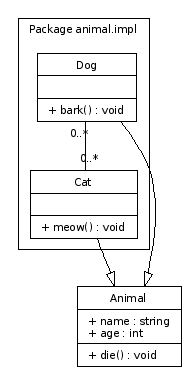
The end result of our dot modelling work.
Further ideas
I hope this article provided a good starting point for drawing UML diagrams automatically using dot. See the UMLGraph website for more ideas on implementing extensions to the basic ideas. I hope you found this information useful.
About this article
This article was added to the site on the 1st of April 2006.
UML Diagrams Using Graphviz Dot的更多相关文章
- How to generate UML Diagrams from Java code in Eclipse
UML diagrams compliment inline documentation ( javadoc ) and allow to better explore / understand a ...
- 将 Graphviz .dot 文件转换为其他格式的图像
参考: Graphviz: How to go from .dot to a graph? 将 Graphviz .dot 文件转换为其他格式的图像 在Linux系统下,使用以下命令: dot -Tp ...
- UML类图(Unified Modeling Language Class Diagrams)
统一建模语言(UML) | 类图 什么是UML? UML是一种用于可视化描述系统,具有广泛用途的建模语言.作为一种标准化的图形语言,在软件工业中被用于软件系统部件的具体化,可视化,结构化描述以及撰写 ...
- 使用DOT语言和Graphviz绘图(翻译)
Casa Taloyum About Me Blog Archives 使用DOT语言和Graphviz绘图(翻译) Date Wed 26 November 2014 Tags graphviz / ...
- Tools - UML
ProcessOn - 在线绘图工具 ProcessOn 支持流程图.思维导图.原型图.UML.网络拓扑图等: 主流的UML图列都支持,可以作为方便快捷的UML工具: PlantUML - 多系统多编 ...
- Linux命令之dot - 绘制DOT语言脚本描述的图形
本文链接:http://codingstandards.iteye.com/blog/840055 用途说明 Graphviz (Graph Visualization Software的缩写)是一个 ...
- 【实践】源代码分析工具Doxygen+Graphviz
拿到一个新项目或者一个开源框架,看源代码的方式不是先进行单步调试!最好的方式是先画出整个项目或者开源框架的类.协作.已经方法调用图,能够帮助你更快的理解框架或者项目的设计. 打包下载地址:http:/ ...
- 转:深入浅出UML类图(具体到代码层次)
深入浅出UML类图 作者:刘伟 ,发布于:2012-11-23,来源:CSDN 在UML 2.0的13种图形中,类图是使用频率最高的UML图之一.Martin Fowler在其著作<UML ...
- 深入浅出UML类图(一)
在UML 2.0的13种图形中,类图是使用频率最高的UML图之一.Martin Fowler在其著作<UML Distilled: A Brief Guide to the Standard O ...
随机推荐
- c++ 向main传递参赛
1.今天写了个批处理文件 准备向main传递参赛 发现在vs2008运行正常 vs2010运行只有首字母 2.需要在项目--属性--常规-字符集里面设置成多字节就好了,以前是unicode 3.因为 ...
- github前端资源
摘要: 本文将分享我在github上常用的一些插件,可能在开发中你会用到它,希望能够帮助你! 前端技术总结 url : https://github.com/JacksonTian/fks 简述: ...
- Git 的BUG小结
Git 的BUG小结 Git 在push的时候出现了: fatal: The remote end hung up unexpectedly 在网上找了非常多 发现出现了下面错误提示也可能是同样的问 ...
- Emulator Error: Could not load OpenGLES emulation library: Could not load DLL!
Copy the file below from SDK\tools\lib to SDK\tools. libEGL_translator.dlllibGLES_CM_translator.dlll ...
- 切换sprite
using UnityEngine; using System.Collections; public class BTN : MonoBehaviour { void Awake () { //s ...
- Win8/8.1下驱动安装“数据无效”错误的有效解决方法
Windows8.1 安装完vmware 后并没有安装 vmnet1,vmnet8 这两个虚拟网卡,纠结了半天,原来是两个服务没打开. 如果你使用的是Windows8或者8.1,并且精简过系统,那么在 ...
- Java中list对象的三种遍历方式
1.增强for循环 for(String str : list) {//其内部实质上还是调用了迭代器遍历方式,这种循环方式还有其他限制,不建议使用. System.out.println(str); ...
- Delphi数据类型转换
[转]Delphi数据类型转换 DateTimeToFileDate 将DELPHI的日期格式转换为DOS的日期格式 DateTimeToStr 将日期时间格式 ...
- Linux系统下编译连接C源代码
gcc test.c -o test 一步到位的编译指令 得到 test 文件 gcc test.c 得到 test.out 文件 gcc -g -c test.c -o test 只生成目标文件(. ...
- EUI组件之Button
一.Button的常规使用 用到的按钮素材,分别为按钮的正常.按下.禁用图片 拖动一个Button到exml,并设置正常.按下.禁用.标签等属性 点击效果 其他: 1. 按钮的标签字体颜色大小怎么改变 ...