Fisheye projections from spherical maps
Written by Paul Bourke
May 2003, software updated January 2016
See also: Mapping a equirectangular projection to perspective
The source code implementing the projections below is only available
on request for a small fee. It includes a demo application and an invitation to
convert an image of your choice to verify the code does what you seek.
For more information please contact the author.
"sphere2fish" takes a full spherical map and generates fisheye views
given a center position for the fisheye, optionally an up vector, and an
aperture from 0 to 360 degrees. In addition, the user may choose the
level of antialiasing (supersampling) and an option to create a circularly
bounds fisheye (traditional) or a rectangularly bound fisheye (the later is
usually only appropriate for smaller aperture angles). The application is
in the form of a UNIX style command line interface, a TGA file is expected
for the input image (24 or 32 bit RGB), the output fisheye image is
written to standard output. The usage message is given below.
Usage: sphere2fish [options] sphereimage

Options

   -w n       width and height of the fisheye image, default = 512

   -t n       fisheye aperture (degrees), default = 180

              maximum is 360 degrees

   -c x y     center longitude and latitude of fisheye, default = 0 0 degrees

   -u x y z   up vector, default = (0,0,1)

              required for latitude = +- 90 degrees (poles)

   -f         full rectangular fisheye instead of circular crop

   -a n       antialiasing level, default = 2

   -o s       output file name, name derived from input filename

   -bg r g b  background image colour (outside fisheye circle), default = 0 0 0

   -bf        back fade to black, reduce interreflections
The conventions used with the program as drawn below. In particular, zero longitude and latitude are taken to be in the center of the spherical image.
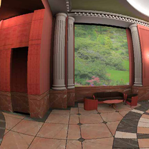
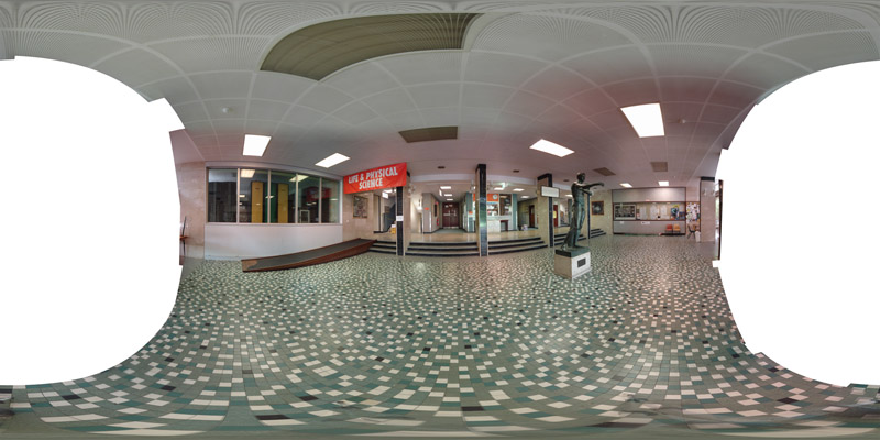
The following spherical image will be used to illustrate (and test) various capabilities of the fisheye generator.
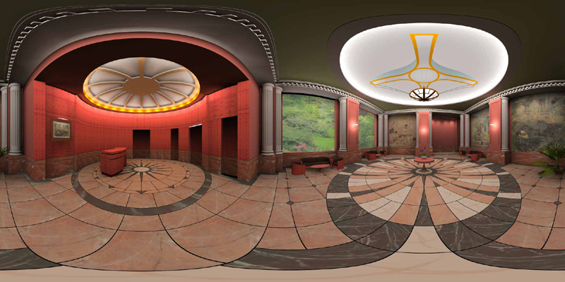
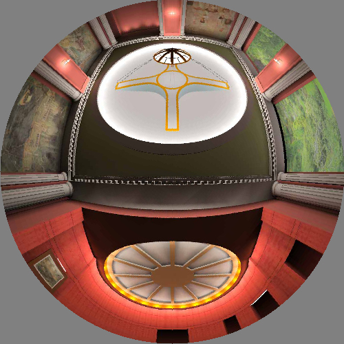
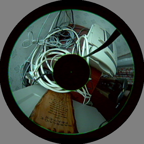
Default view conditions
sphere2fish lobby.tga > 1.tga
|
|
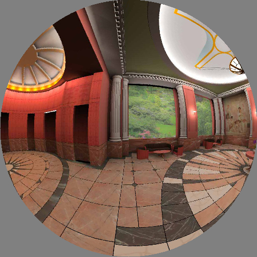
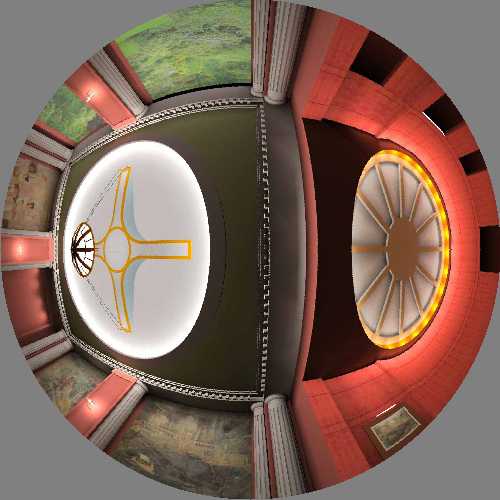
From 90 degrees longitude
sphere2fish -c 90 0 lobby.tga > 2.tga
|
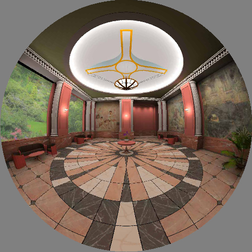
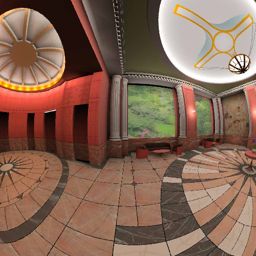
From 45 degrees latitude
sphere2fish -c 0 45 lobby.tga > 3.tga
|
|
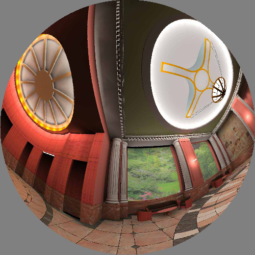
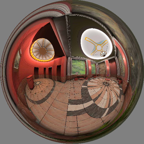
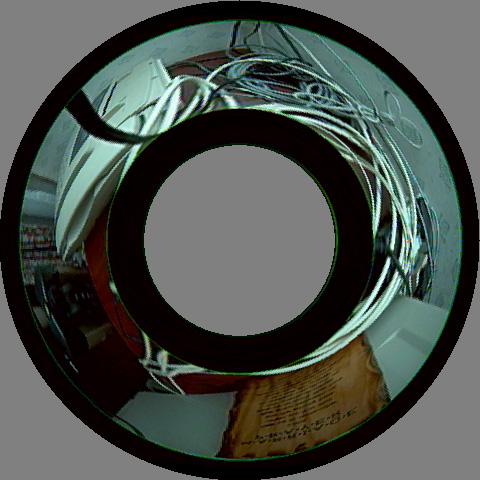
Fisheye from north pole
sphere2fish -c 0 90 lobby.tga > 4.tga
|
Fisheye from north pole and with different up vector
sphere2fish -c 0 90 -u 0 1 0 lobby.tga > 5.tga
|
|
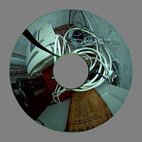
Extend to whole rectangular range
sphere2fish -f lobby.tga > 6.tga
|
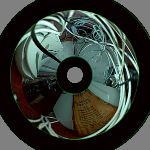
Full 360 degree fisheye
sphere2fish -t 360 lobby.tga > 7.tga
|
|
90 degree fisheye
sphere2fish -t 90 -f lobby.tga > 8.tga
|
Camera roll
sphere2fish -c -60 0 -u 0 1 1 lobby.tga > 9.tga

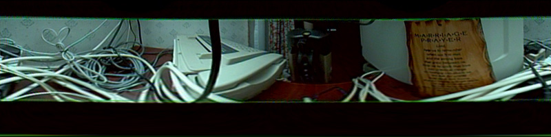
Photographic example
The following is a spherical projection stitched from 50 images using AutoPano Pro.
Only a 1/2 hemisphere is captured. The original spherical projection image is
22000x11000 pixels.
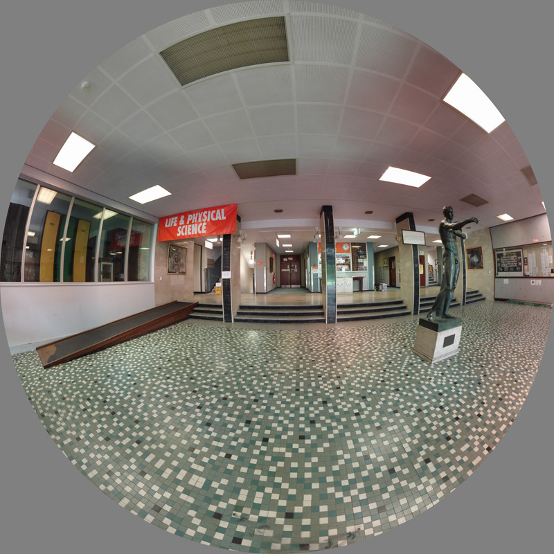
In this case only one fisheye can be captured. If the full spherical projection was captured
(only requiring twice the number of individual images) then a fisheye pointing in any
direction can be sampled. The original fisheye images can be up to 10,000 pixels square.

Converting Images from Panoramic to Dome
Written by Paul Bourke
February 2002
Example images courtesy (and copyright) Astro Copy Service,
Planetarium Augsburg, Germany
See also Angular fisheye projections.
The following will discuss the conversion of panoramic images into
those suitable for display onto a dome, in particular, angular
fisheye as used by the majority of planetarium domes. There are
a number of panoramic image formats, they all use the same horizontal
axis which ranges from 0 to 2 pi. There are however a number of
vertical distortions, the two most common are considered here.
One is often called a radial panoramic where the vertical axis
is considered to lie on the surface of a sphere, the other is a
linear panoramic where the vertical axis results from a standard
perspective projection. This second is the most common, the image
is obtained by projecting onto a cylinder about the camera.
As with most mappings the goal is to estimate the colour for each
pixel in the destination image. The destination image in this case
is the angular fisheye, the colour estimate will be determined by
the corresponding
pixels in the source (panoramic) image. In general there isn't a
single pixel in the input image corresponding to a particular pixel in the
destination image. For best results it is usual to find the closest
pixel in the input image for a range of positions within each pixel
in the destination image, these are averaged together to determine
the final estimate of the colour. This is commonly called antialiasing,
the simplest form of which is to estimate the colour by averaging over
a 2x2 or 3x3 grid within each pixel.
The basic idea is to find the mapping between
a coordinate system in the angular fisheye and a coordinate system in the
panoramic image. The convenient coordinate system in the angular fisheye
is "r" (the distance from the center of the pixel to the pixel in
question) and the angle "phi" (angle of the vector to the pixel).
The convenient coordinate system in the panoramic image is the same
angle "phi" (the vertical axis of the panoramic), in both images this
angle varies from 0 to 2 pi. The vertical axis of the panoramic is
proportional to the "r" in the angular fisheye. This is illustrated
in the following figure.
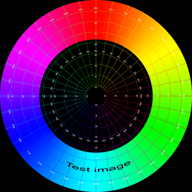
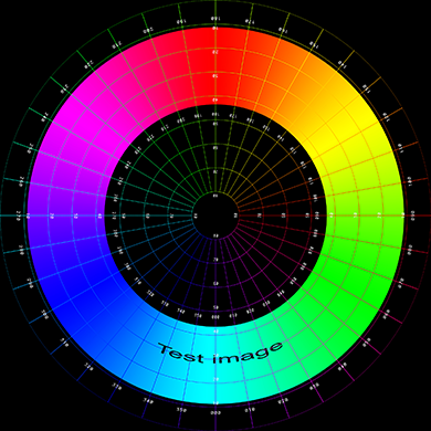
The conversion of the two types of panoramic image will be illustrated
by transforming the following test pattern. This will be done for three
values of thetamax, that is, the panoramic images will be assumed to
vary vertically from 0 to 30, 60, and 90 degrees.
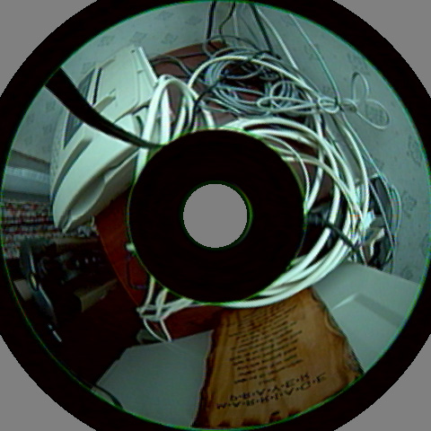
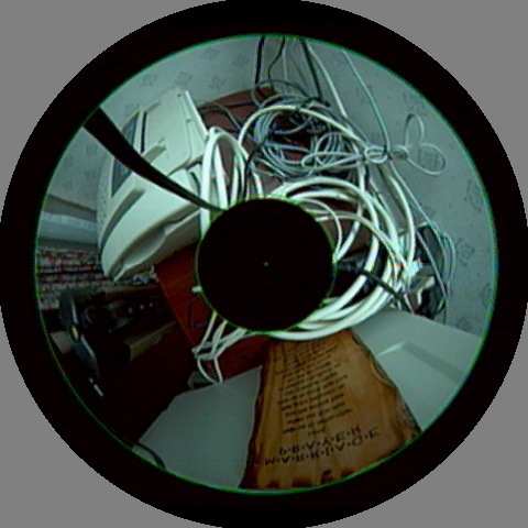
Radial panoramic
The hole in the center for all but the 90 degree case reflects the lack
of image data from thetamax to 90 degrees which is the central
portion of the fisheye image.
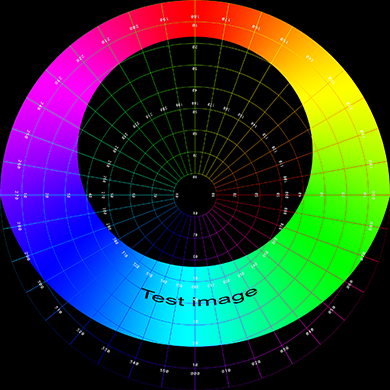
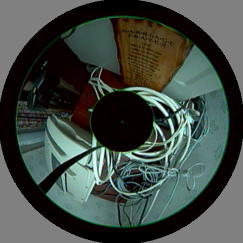
Linear panoramic
The most obvious feature of this case is the extreme distortion
that occurs as the fisheye tends to 90 degrees. Of course, while
the distortion seems extreme below that is because the test image
has a equal spacing grid, something that would not normally occur in a
90 degree panoramic. A normal 90 degree panoramic would appear very
distorted itself and the process of turning that into a dome image
would correct for the distortion.
The following is a
linear 45 degree angular fisheye of the panoramic shown at the top
of this page.
Notes
It has been assumed here that the panoramic extends from 0 degrees
upwards along the vertical axis. This is because the discussion here
has been targeted towards turning panoramas into images for
projection in planetarium domes where one only sees above the
horizon in both the panoramic and fisheye. Radius of the dome image is related to the length of the
panoramic, namely, the diameter of the dome image is the
width of the panoramic divided by pi. Other dome dimensions
will result in a radial compression or stretching.
Further Examples
pan2sph panfilename [options]

Options:

-t n       set max theta on vertical axis of panoramic, 0...90 (default: 45)

-a n       set antialias level, 1 upwards, 2 or 3 typical (default: 2)

-w n       width of the dome image, height = width (default: 512)

-s         use sine function correction (default: off)

-r n       rotation angle, 0...nx (default: 0)

-f         flip insideout (default: off)

-bg r g b  set background colour, 0...255 each (default: 0 0 0)
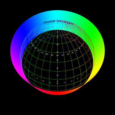
Diagram illustrating panorama within a circular fisheye for planetarium use
Further exercise
December 2004
Usage: pano2fish [options] fisheyeimage

Options

-w n      fisheye image width and height, default = -1

-r r1 r2  inner and outer radius of the fisheye image

-h h1 h2  top and bottom panoramic edges

-a n      antialiasing level, default = 1 (no antialising)

-d        change direction of panoramic

-p n      rotate by n degrees

-c        clear region outside fisheye radius
Example
Input image
|
Default settings
pano2fish -w 480 pano.tga
|
|
Set panoramic height range, measured from bottom of the image
pano2fish -a 2 -h 172 50 -w 480 pano.tga
|
Set the fisheye radius range, measured from the center of the fisheye
pano2fish -a 2 -h 172 50 -r 208 60 -w 480 pano.tga
|
|
Reverse panoramic direction
pano2fish -a 2 -h 172 50 -r 208 60 -w 480 -d pano.tga
|
Change phase
pano2fish -a 2 -h 172 50 -r 208 60 -w 480 -d -p 180 pano.tga
|
|
Invert mapping by swapping radius bounds
pano2fish -a 2 -h 172 50 -r 60 208 -w 480 pano.tga
|
Clear region outside radius range
pano2fish -a 2 -h 172 50 -r 208 60 -w 480 -c pano.tga
|
Rendering software solution.
Update: February 2016
There are now a number of plug-ins for compositing packages that allow one
to work in polar coordinates, rather than Cartesian coordinates and also allow
one to place various image projections (perspective, cylindrical, equirectangular)
into the fisheye image space.
But if one is used to a 3D modelling/rendering package or if one is creating
realtime content then an alternative approach is to compose the non-fisheye
elements in the 3D scene and then simple render the fisheye. For plane perspective
images these may be placed on a billboard in the scene, at the desired position
and angle. The image will appear on a flat surface in the dome oriented, positioned
and sized as set in the model.
In the case relevant here, one could place a cylinder in the 3D model world with
the panorama on the surface as a texture. This cylinder should have the same horizontal
angular extent as the panorama, not necessarily a full 360 degrees. The height of the cylinder
would normally be fixed to the right aspect ratio of the panorama but the position and
angle of the panorama could be varied as desired. Indeed, rotating and tilting the cylinder is
a standard type of dome transition or way of enlivening what is otherwise a static image (of
course the texture could also be a video sequence). Again, rendering the fisheye of the
textured cylinder will ensure the geometric effect in the dome is the same as within
the 3D model.
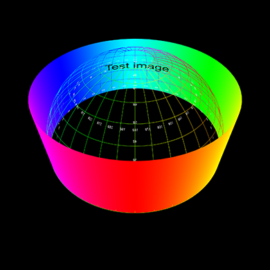
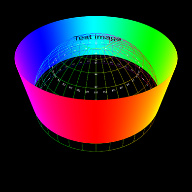
Some examples are shown below, on the left is a view of the cylinder in relation to
a polar grid representing the dome. On the right is the fisheye rendered from the
middle of the dome.
The examples here are created using PovRay but any 3D modelling/rendering package
that supports a circular fisheye lens could be chosen.
Raising the cylinder above the spring line of the dome.
Rotating the cylinder with respect to the dome axis.
网址:
http://paulbourke.net/dome/2fish/
|