
How to evaluate a transimpedance amplifier (part 1)
In this blog, I want take a different approach and describe the technical challenge encountered while bench characterizing the OPA857, a dedicatedtransimpedance amplifier (TIA) with two internal gain settings operating on a +3.3 V supply supporting a minimum of 100MHz bandwidth.
Besides the combination of both high-gain (5kΩ and 20kΩ) and high-bandwidth (>100MHz over temperature and process variation), the most challenging characteristic of the OPA857 is the need for low input capacitance requirement. This requirement, including the board parasitic, is to have the total input capacitance less than 1.5pF. Just as a clarification, the 1.5pF of total input capacitance does not include the package or the transistors parasitic. This value was selected because the OPA857 is driven by a photodiode whose biasing voltage is high enough to have the photodiode capacitance contribution between 0.5pF and 0.7pF, leaving between 0.8pF to 1pF for external parasitic.
OPA857 introduction
The OPA857 is a dedicated TIA with pseudo-differential output. The block diagram is provided in figure 1 below.
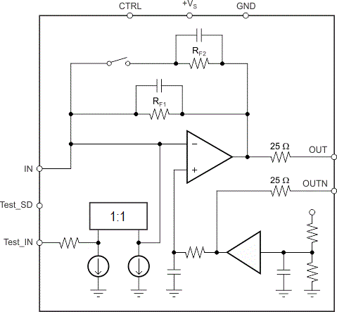
Figure 1: OPA857 block diagram
There are three distinct blocks in this diagram:
- Transimpedance block
- Reference voltage block
- Current mirror block (test block)
The transimpedance block has two selectable gain configurations: 4.5kΩ and 18.2kΩ when taking into consideration the attenuation due to a 500Ω load. Since there is only one switch, the parallel combination of the RF2 with RF1 is 4.5kΩ. The schematic is simplified to ensure that the resulting value is represented clearly.
The transimpedance block was designed to provide excellent bandwidth (>100MHz) in both gain configurations with the lowest possible RMS noise over its entire bandwidth.
The reference voltage block has several purposes:
- Provide the adequate DC-reference voltage to the input.
- Provide a DC-reference at the output allowing the DC-coupled solution to fully differential signal chain, which in turn provides CMRR as well as converting PSRR issue into CMRR.
The third block available on the pinout is intended to simplify the characterization and the evaluation of the OPA857. Before going further in this device feature and how to characterize it, let’s have a look at the expected measured performance. One of the requirements is to measure as directly as possible in the intended application circuit.
- Frequency response
- Pulse response
- Harmonic Distortion
Reference block
The reference block is set to be 5/9th of the power supply. So for 3.3 V, the reference voltage is 1.8 V. The high bandwidth allows low output impedance to high frequencies. The reference voltage is then fed to two paths. One path leading to the output OUTN has a 25Ω series resistor. The other path has a series RC going to the non-inverting input of the TIA. The RC filter is used to minimize the high frequency noise coming from the reference voltage at the buffer input.
TIA block
The amplifier of the TIA block has a class-A output stage, limiting its swing down from the common-mode voltage of 1.83 V almost all the way to the rail. Due to the internal protection, added for both protection and the improved overdrive recovery, it is not possible to swing closer to the rail than 0.6V. This still leave 1.2 V swing on the output for the dynamic range, corresponding to a maximum input current of 60uA in the 20kΩ gain and 240uA in the 5kΩ gain.
A 25Ω series resistance is also found on each output, limiting the loading the amplifier experiences, but also reduces the gain. With a 500Ω differential load, the attenuation due to the load is 0.83dB, which impacts the overall transimpedance gain. Due to the load attenuation, the 20kΩ transimpedance gain is reduced to an effective 18.2kΩ while the 5kΩ is reduced to an effective 4.5kΩ.
Bandwidth consideration
Due to its fixed transimpedance configuration and associated internal compensation, the source input capacitance must stay low as stated earlier. The nominal design target is 1.5pF including board parasitic. It is not recommended to have an input capacitance in excess of 5pF for maximum flatness in the 5kΩ gain. At 5pF input capacitance, the OPA857 in the 20kΩ gain will peak 1.5dB. See figure 2a) and 2b) below: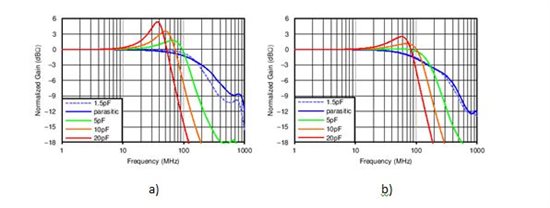
Figure 2: a) 20kΩ gain, b) 5kΩ gain
Note also that the bandwidth will vary with the load: the heavier the load, the lower the bandwidth. See figure 3 below.
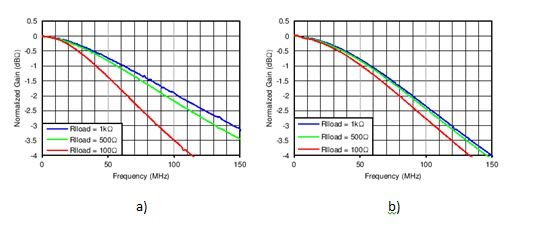
Figure 3: OPA857 bandwidth variation with load, a) 20kΩ, b) 5kΩ
Now that we have reviewed the expected performance of the amplifier, in my next post we can look into actually implementing the measurements.
How to evaluate a transimpedance amplifier (part 1)的更多相关文章
- How to evaluate a transimpedance amplifier (part 2)
In my previous blog on "How to evaluate a transimpedance amplifier, part 1", we looked at ...
- [转]What you need to know about transimpedance amplifiers – part 1
Transimpedance amplifiers (TIAs) act as front-end amplifiers for optical sensors such as photodiodes ...
- Could not evaluate expression
VS15 调试变量不能显示值,提示:Could not evaluate expression 解决办法: 选择"在调试时显示运行以单击编辑器中的按钮"重启VS即可. 可参考:Vi ...
- [LeetCode] Evaluate Reverse Polish Notation 计算逆波兰表达式
Evaluate the value of an arithmetic expression in Reverse Polish Notation. Valid operators are +, -, ...
- Evaluate Math Expression
Evaluate Math Expression eryar@163.com 摘要Abstract:本文简要介绍了数学表达式解析求值的几款开源软件,并结合程序代码说明了OpenCascade中表达式包 ...
- RobotFrameWork(四)变量运算与Evaluate
一.特殊变量运算: 执行结果: 二.Evaluate使用 函数释义:Evaluate是执行Python表达式,并返回执行结果 示例1: 执行结果: 示例2: 执行结果:
- 【leetcode】Evaluate Reverse Polish Notation
Evaluate Reverse Polish Notation 题目描述: Evaluate the value of an arithmetic expression in Reverse Pol ...
- 使用centos引导内核错误:kernel: pnp 00:0b: can't evaluate _CRS: 8
CentOS系统在开机过程中,一直遇到黑屏提示:“kernel: pnp 00:0b: can't evaluate _CRS: 8”,不理会它仍能启动系统并正常工作,未知何故. 经查,这是内核引导的 ...
- The Non-Inverting Amplifier Output Resistance by Adrian S. Nastase [ Copied ]
Source Address: http://masteringelectronicsdesign.com/the-non-inverting-amplifier-output-resistance/ ...
随机推荐
- C# 时间现实问题(12小时制与24小时制)
最近在修改项目中遇到时间问题,12小时制与24小时制的问题,想再次跟各位同仁提个醒. yyyy-MM-dd HH:mm:ss------大写的HH为24小时制 yyyy-MM-dd hh:mm:ss- ...
- 通过进程检测服务时脚本文件名不要起要检测的服务名字命名 shell程序从上到下执行若定义函数或引用系统函数需先定义 kill -USR2
通过进程检测服务时脚本文件名不要起要检测的服务名字命名 kill -USR2 `cat /var/run/mysqld.pid`
- 鸟哥的linux私房菜学习记录之例行性工作
- V4L2驱动程序框架架构【转】
本文转载自:http://blog.csdn.net/tommy_wxie/article/details/11728809 1 V4L2简介 video4linux2(V4L2)是Linux内核中关 ...
- #import vs. @class
You #import or #include when there is a physical dependency. Otherwise, you use forward declarations ...
- DOS下如何同时显示时区日期和时间
DOS下如何同时显示时区日期和时间 Echo %Date:~0,4%-%Date:~5,2%-%Date:~8,2% %Time:~0,2%:%Time:~3,2% 不显示周几 Echo %Date: ...
- PyChram使用技巧总结
1.1 下载 官网1.2 汉化 1.3 添加或者修改文件模板 File->settings->Editor->File and Code Templates->Python S ...
- ecshop简单三部实现导航分类二级菜单
1.在page_header.lbi对应的位置(你想显示导航的位置)插入 (注意下面的"themes/模板名称/util.php"中的"模板名称"改成你模板文件 ...
- OA系统如何使用考勤机数据
通达OA系统使用考勤机数据目前有两种方法可以实现:一种是通过进行二次开发,将通达OA系统与考勤机结合起来使用:另一种是通过将考勤机的数据导出再导入OA系统中.进行二次开发的话,需要和定制开发工程师联系 ...
- java 面试每日一题3
题目:求s=a+aa+aaa+aaaa+aa...a的值,其中a是一个数字.例如2+22+222+2222+22222(此时共有5个数相加),几个数相加有键盘控制. import java.io.Bu ...