
How to evaluate a transimpedance amplifier (part 2)
In my previous blog on "How to evaluate a transimpedance amplifier, part 1", we looked at the OPA857 performance, but didn’t go in depth in explaining how those measurements were taken. Now that we’ve have established a reference, let’s work through the implementation.
To summarize, the main challenges to taking measurements with the OPA857 include:
- Transimpedance configuration
- Low input capacitance
- High output impedance
With a 20kW gain and a 1VPP output voltage swing the input current needs to be 50mAPP. Since the output voltage swing of the OPA857 is class A and the current flowing through a transimpedance is unipolar, the output common-mode voltage will need to be set appropriately.
The current source needs to be low capacitance, less than 1.5pF, to maintain the bandwidth. The output needs to be high output impedance to control the loading on the OPA857’s output. Since most of the test equipments we have are 50W input and output impedance, how do we resolve that problem while not impacting bandwidth, slew rate or distortion performance of the DUT (Device Under Test)?
This leads to individual solution for each measurement type.
The first measurement we will look at is the frequency response, or S21 parameter. For that we’ll use an HP 8753ES Network analyzer, a 30kHz to 6GHz S Parameter Network Analyzer. Both input and output are 50W impedance and AC-coupled. There are two ports in the back of the analyzer that allow controlling the DC voltage on either the input or output.
The two proposed signal chains to measure the OPA857 frequency response include:
- Using a high speed differential probe, see figure 1.
- Using a high speed buffer to isolate the network analyzer’s load, see figure 2.
Note that the Test_SD pin is set to a logic high (+3.3V) for the internal current source to operate properly. This implies that the DC voltage present on the Test_IN input will set the output voltage appearing on OUT and requires you implement the following procedure to ensure that the OPA857 operates optimally for an AC response.
- Minimize the AC signal.
- Set DC voltage at input such that the output voltage can swing around it preset common-mode voltage. For example, if the signal swing is 500mVPP, then the OUT DC voltage needs to be set to ≤1.4V. If this is not the case, the output swing will clip as the current in the class-A output stage runs out.
- After completion of #1, do not leave anything connected on the output. A probe lead or a voltage will add several pF to the load, altering the frequency response.
- Set the AC amplitude to the desired peak-peak output signal swing.
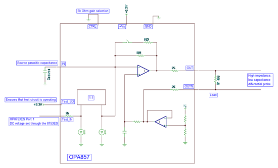
Figure 1: Circuit #1 using a fully differential probe to interface to the HP8753ES.
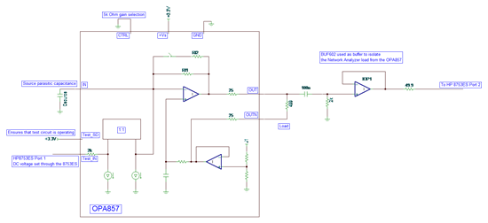
Figure 2: Circuit #2 using a BUF602 to interface to the HP8753ES.
The same approach is used to evaluate pulse response or any time domain measurement. Note however that since no resistor tolerance inside theOPA857 is better than ±15%, the setup will have to be calibrated device by device.
The approach described above will not work for measuring harmonic distortion, so how does this new problem get resolved?
The traditional approach for measuring harmonic distortion requires:
- A low distortion source
- A high dynamic range spectrum analyzer
The low distortion source is further improved by using a high order filter. The dynamic range of the spectrum analyzer can be improved by filtering the fundamental and measuring only the harmonics. The setup is shown in figure 3. The notch filter that can is placed after the DUT is omitted in this diagram.
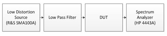
Figure 3: Traditional harmonic distortion bench measurement setup.
In the case of the OPA857, we have two problems. The first one is that the source is a voltage source and that the input signal requires a current source. The internal current source cannot be used here as it does not have sufficient linearity. So we will have to develop a low distortion current source to enable the measurement. The second problem is the interface to the spectrum analyzer. The output of the OPA857 is pseudo-differential and requires driving a light load, whereas the spectrum analyzer requires a single-ended input and expects 50W.
A current source has high output impedance. In our case, the current source will need to have low input capacitance as well, so it cannot be generated using transistor-based circuit as a large transistor will also have a high intrinsic capacitance, not considering the package and board layout parasitic. This limits the approach to using a voltage source and converting it to a current using a resistor. In order to ensure that the noise gain of the OPA857 is close to 1V/V, the same as the transimpedance configuration, the source capacitance is minimal and the resistance is large enough to approximate this.
The source capacitance is minimized by careful insertion of a series resistor on the inverting pin. Please refer to the OPA857 EVM for the layout.
In our case, the gain resistor is five times the value of the transimpedance gain, so for 20kΩ, the current source impedance is 100kΩ. It is a compromise as the noise gain is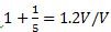 . This represents a degradation of ~1.6dB due to the loss in loop-gain in the measurement which would not be present in a transimpedance configuration.
The OPA857 is operating in an attenuator configuration, so a 0.5VPP on its output now requires 2.5VPP from the generator further increasing the non-linearity from the source.
Looking at the output of the OPA857, we need to measure the nominal 500Ω load and also measure the non-linearity of the amplifier as the load is decreased to 5kΩ. So, again the interface between the OPA857 and the spectrum analyzer is not purely resistive as there is too much attenuation of the signal and parasitic capacitance on the output after the resistance would limit the effective bandwidth. If an active element is inserted in the signal chain, its distortion must be 15dB better than the expected measurement to degrade the measurement by 0.1dB. This tends to be a relatively easy requirement at low frequency, but is quickly unmanageable as the frequency increases. The solution here is to use a DVGA developed for the telecommunication market as it provides sufficient gain to compensate for attenuation in the signal path, since those DVGAs have a 200Ω input impedance, as well as convert the pseudo differential signal to fully differential and have sufficient linearity up to the frequency of interest. A transformer on the output of the DVGA converts the amplified fully differential signal and converts it to the single-ended input the spectrum analyzer expects. We will have some attenuation losses here as well to match the 50Ω input impedance of the test equipment. Finally the signal chain on the output of the OPA857 will look like the diagram shown in figure 4.
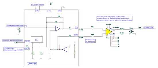
Figure 4: OPA857 with PGA870 used to adapt the OPA857 load into the Spectrum Analyzer.
The PGA870 provides additional gain with high linearity minimizing the measured linearity degradation. Looking into the PGA870 datasheet, we see that operating at high gain (> +10dB), both the 2nd and the 3rd harmonic distortion is greater than 90dBc for a 2VPP output swing. This ensures that theOPA857 measurement is degraded by less than 0.1dB.
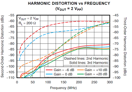
Figure 5: PGA870 Harmonic distortion for 200Ω load.
In this blog, I have shown the techniques used to measure most of the typical characteristic curves shown in the OPA857 datasheet. For application information or how to implement the OPA857, refer to the datasheet and EVM user guide.
How to evaluate a transimpedance amplifier (part 2)的更多相关文章
- How to evaluate a transimpedance amplifier (part 1)
In this blog, I want take a different approach and describe the technical challenge encountered whil ...
- [转]What you need to know about transimpedance amplifiers – part 1
Transimpedance amplifiers (TIAs) act as front-end amplifiers for optical sensors such as photodiodes ...
- Could not evaluate expression
VS15 调试变量不能显示值,提示:Could not evaluate expression 解决办法: 选择"在调试时显示运行以单击编辑器中的按钮"重启VS即可. 可参考:Vi ...
- [LeetCode] Evaluate Reverse Polish Notation 计算逆波兰表达式
Evaluate the value of an arithmetic expression in Reverse Polish Notation. Valid operators are +, -, ...
- Evaluate Math Expression
Evaluate Math Expression eryar@163.com 摘要Abstract:本文简要介绍了数学表达式解析求值的几款开源软件,并结合程序代码说明了OpenCascade中表达式包 ...
- RobotFrameWork(四)变量运算与Evaluate
一.特殊变量运算: 执行结果: 二.Evaluate使用 函数释义:Evaluate是执行Python表达式,并返回执行结果 示例1: 执行结果: 示例2: 执行结果:
- 【leetcode】Evaluate Reverse Polish Notation
Evaluate Reverse Polish Notation 题目描述: Evaluate the value of an arithmetic expression in Reverse Pol ...
- 使用centos引导内核错误:kernel: pnp 00:0b: can't evaluate _CRS: 8
CentOS系统在开机过程中,一直遇到黑屏提示:“kernel: pnp 00:0b: can't evaluate _CRS: 8”,不理会它仍能启动系统并正常工作,未知何故. 经查,这是内核引导的 ...
- The Non-Inverting Amplifier Output Resistance by Adrian S. Nastase [ Copied ]
Source Address: http://masteringelectronicsdesign.com/the-non-inverting-amplifier-output-resistance/ ...
随机推荐
- C#下调用C++ SDK的编码常识
一组编码规范,通过C#调用C++ 自动封装的C# SDK,会发现面向对象思想的重要性. C++ SDK可以使用自动封装工具转换成C# SDK.但需要遵守如下规则: 1.如果需要对C#对象进行判断,则分 ...
- BI案例:BI在连锁零售业应用(ZT)【转】
第一部分:连锁零售企业上BI的必要性. 目前国内的连锁零售行业的发展趋势,呈现出产业规模化,经营业态多样化,管理精细化的特点.所谓管理精细化就是"精耕细作搞管理,领先一步订系 统" ...
- Linux的视频编程(V4L2编程)【转】
本文转载自:http://blog.csdn.net/tommy_wxie/article/details/11472073 一.什么是video4linuxVideo4linux2(简称V4L2), ...
- Linux kernel的 Makefile和Kconfig以及Make menuconfig的关系【转】
本文转载自:http://blog.sina.com.cn/s/blog_4ba5b45e0102e6vp.html 熟悉内核的Makefile对开发设备驱动.理解内核代码结构都是非常重要的linux ...
- 利用arcigs制作出 源解析要用的ASCII文件
准备:1.确定好模拟区域范围,精度,行列数 2.确定好源解析的城市规划 思路: 1.全国省级图+本地市县图-->合成一张区域图(联合) 合成之后,添加一个字段,一个数字类型字段 ...
- Dynamics AX 2012 R2 Business Connector Error
6.0: AxCryptoClient - New encryption key created 6.0: Unable to InitializeSession. 6.0: No built-in ...
- HDU 2136:Computer(树形DP)
http://acm.split.hdu.edu.cn/showproblem.php?pid=2196 Computer Description A school bought the fi ...
- java 面试每日一题4
题目:有1.2.3.4个数字,能组成多少个互不相同且无重复数字的三位数?都是多少? 1.程序分析:可填在百位.十位.个位的数字都是1.2.3.4.组成所有的排列后再去 掉不满足条件的排列. publ ...
- android应用的数据应该保存到哪儿
王永超王永超嫖娼 做android app开发会涉及到不同数据的保存,比如数据缓存,客户登陆信息保存,客户状态的保存等等. 那针对这不同的数据我们应该保存在什么地方呢? 1.应用卸载也不会删除的数据 ...
- c# UDP
using System; using System.Collections.Generic; using System.ComponentModel; using System.Data; usin ...