Bringing up the Avnet MicroZed with Vivado
Bringing up the Avnet MicroZed with Vivado
I recently received the Adam Taylor Edition of Avnet's Zynq-based MicroZed board, which was sent by the very kind people at Xilinx. I have been writing about the ZedBoard for a while now over on All Programmable Planet. For the original ZedBoard, I used the more traditional PlanAhead, Xilinx Platform Studio, and Software Design Kit (SDK) flow. With that in mind, I decided that for the MicroZed I would implement the system using the Xilinx Vivado Design Suite, which turned out to be surprisingly easy. My aim is to progress with the MicroZed in a similar manner to the ZedBoard: looking at creating the system, using the on-chip XADC, boot-loading the MicroZed, adding my own peripheral, and finally adding an operating system. I expect this will progress rapidly expect due to my familiarity with the ZedBoard.
The first step is to download the MicroZed board definition and configuration, which are available at http://www.zedboard.org/documentation/1519. The first file to download is the MicroZed board definition file, which should be extracted to your Xilinx implementation directory. In my case, the directory is loacated at C:\Xilinx\Vivado\2013.2\data\boards\zynq. This file provides the Vivado Design Suite with MicroZed configuration information. The second file you'll need is a TCL file containing the necessary preset information for the MicroZed. We'll run this TCL file once we have created a project.
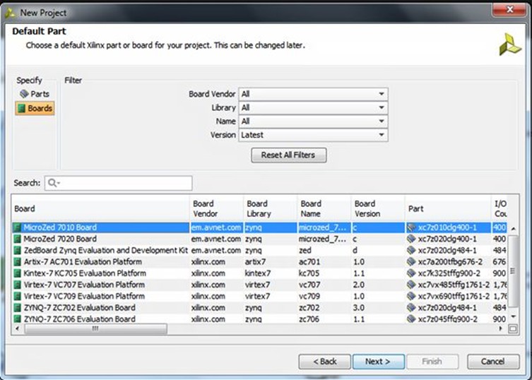
After starting Vivado, the first step is to create a new project. My first MicroZed project will be an RTL project and will not contain any initial source code. The next step is to select the MicroZed 7010 board as a default target using the definition file just downloaded.
Now that the project is created, we need to add the Zynq SoC's processing system (PS). The best way to do this is to create a new block diagram and add in the Zynq PS from the IP library in Vivado. We can then create a block diagram by selecting the option under the flow-control window on the left-hand side of the Vivado screen.
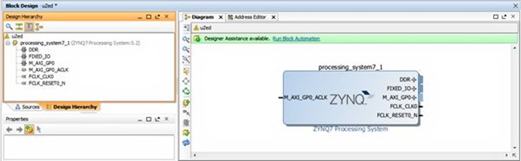
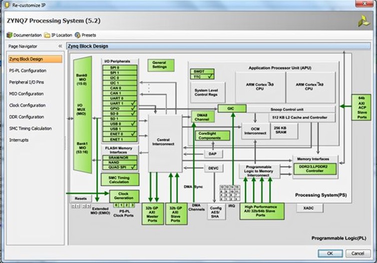
With the PS now added to the block diagram, we need to define the system. We could do this by hand (as would be the case for a custom board). Rather helpfully, the MicroZed people have created a TCL file that defines the MicroZed system. It's the preset file we downloaded at the start. This TCL file defines the PS bank voltages, buses, clocks, fabric clocks, DDR3 settings, external peripherals, and the MIO configuration.
Note: Remember to use linux style forward separators:
"C:/Users/Adam/Downloads/MicroZed_PS_properties_v02/MicroZed_PS_properties_v02.tcl"
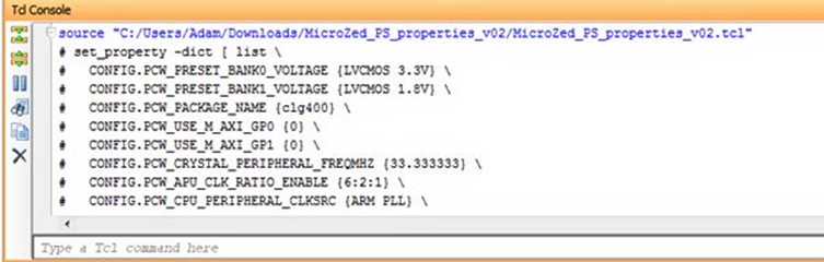
Having applied this file, we then double click on the system and we see the Zynq PS design. Notice that this definition ties up with the capabilities of the MicroZed board's Ethernet, USB, DDR3 etc.
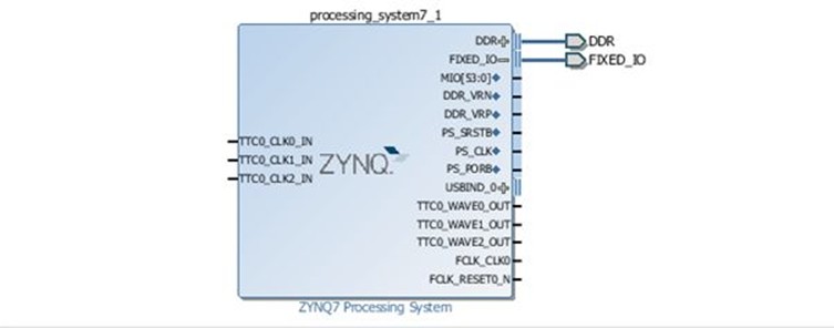
Once we're happy with the PS configuration, we need to declare the system's external I/O. In this case, we want to declare the DDR and the fixed I/O. Within the Zynq PS, the fixed I/O includes the MIO, clocks, and resets along with the DDR3 reference voltages. As these are fixed, no UCF file is required because we are not working with the programmable logic (PL) side of the Zynq. We will need to create UCFs later when we use the Zynq's PL side.
To add these external I/O declarations, you click on the "run design automation" option that appears at the top of the diagram. This will generate a warning. Clicking on "OK" allows you to proceed and you will then see outputs added to the fixed IO and the DDR within the block diagram.
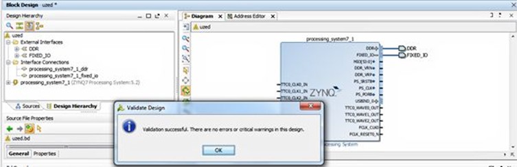
Now we're nearly ready to proceed to build the system. However, we must first validate the design to ensure that it is valid and contains no errors by selecting the "validate design" button on the left side of the Vivado screen.
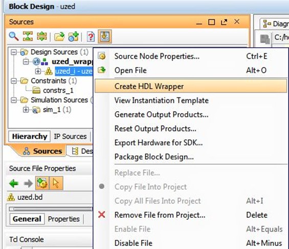
Having created a valid block diagram we will want to save this before we proceed. Once you have saved the design, the next step is to generate the files needed to implement the system, starting with the creation of the HDL wrapper. But first, we need to determine which language we're going to work in (VHDL or Verilog). We select the HDL via the Tools->Project Settings Menu.
Once we've selected our preferred language, we right click on the uzed.bd file under "sources" and select "Create HDL Wrapper" to generate the wrapper.
We can also create the necessary synthesis and place-and-route files by selecting the "Generate Output Products…" option from the same menu that we used to generate the HDL wrapper.
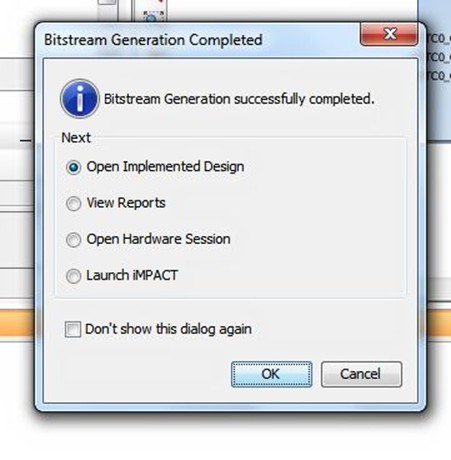
Once these files have been created, it's time to generate the bitstream by selecting the "Generate Bitstream" option in the flow navigator on the left of the Vivado screen. When the bitstream generation completes, you will see:
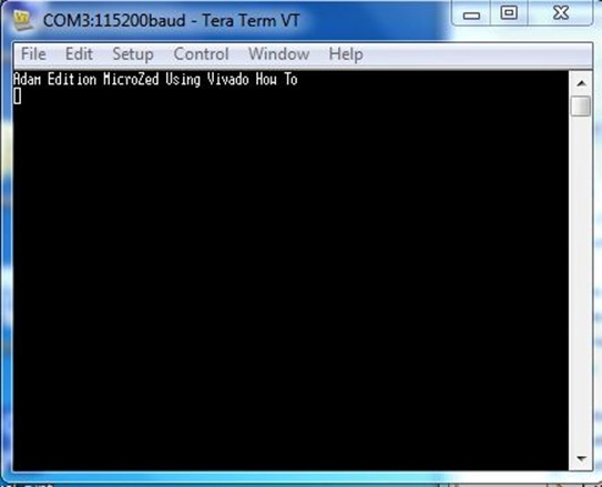
With the bitstream created, we then export the data into SDK. Then we're ready to write the software to run on the MicroZed's Zynq SoC. I'll discuss this process in my next blog, but a sneak peak of where we are headed appears below.
I spent an afternoon bringing up the MicroZed and really enjoyed the experience. My next blog post will wrap up SDK project creation and boot loading with the MicroZed.
Note: Please do not be concerned if you see an error in Vivado version 2013.2 which reports "Failed to get a license:Internal Bit stream." This is a bug in the current version. You can check in the implementation log to make sure that the license was in fact obtained.
Bringing up the Avnet MicroZed with Vivado的更多相关文章
- MiZ702学习笔记9——XADC采集片上数据PS版
这次借助zynq的内嵌的XADC来采集zynq内部的一些参数: •VCCINT:内部PL核心电压 •VCCAUX:辅助PL电压 •VREFP:XADC正参考电压 •VREFN:XADC负参考电压 •V ...
- 第九章 ZYNQ-MIZ701 片上ADC的使用
9.0难度系数★☆☆☆☆☆☆ 9.1实验概述 这次借助zynq的内嵌的XADC来采集zynq内部的一些参数: •VCCINT:内部PL核心电压 •VCCAUX:辅助PL电压 •VREFP:XADC ...
- 第九章 MIZ702 ZYNQ片上ADC的使用
9.0难度系数★☆☆☆☆☆☆ 9.1实验概述 这次借助zynq的内嵌的XADC来采集zynq内部的一些参数: •VCCINT:内部PL核心电压 •VCCAUX:辅助PL电压 •VREFP:XADC ...
- XADC
XADC实验 1.XADC概述 Xilinx7系列内部自带一个双通道12位分辨率的高速(1MSPS 1M sample per second)采样速率的模拟混合信号处理模块,双通道的ADC支持单极和差 ...
- 71.Adam Taylor玩转MicroZed系列第82部分:简单通信接口第2部分
By Adam Taylor 从上周的博客开始,我们已经进入到Zedboard(而不是MicroZed)板上的OLED显示模块的编程了.然而在正式进入具体的OLED编程之前,我认为有必要验证我们是否已 ...
- Vivado SDK 2014.2 创建新工程后,BSP版本不对的解决办法
问题描述如下: 1. 使用Vivado SDK 2014.2已经创建了工程,但是此时,hdf文件增加了外设,需要重新创建工程以更新SDK中的外设描述: 2. 使用新的hdf创建工程后,发现system ...
- notepad++与vivado关联
notepad++与vivado关联 打开vivado软件,选择菜单栏“Tools——>Options…”,在弹出的对话框中,选择General选项卡,如图1所示. 图1 选择General选 ...
- [转载]Vivado轻松实现IP封装
Vivado轻松实现IP封装 1.新建一个测试工程 工程化的设计方法是离不开工程的,第一步往往都是新建工程,后面我会学习去工程化的开发方法,可能会更加高效. 2.利用向导完成IP封装 2.1.启动IP ...
- 在vivado中使用attribute
之前最常用的一个attribute就是mark_debug了,语法如下:(*mark_debug="ture"*). 今天又学到几个新的,原文在这里:http://china.xi ...
随机推荐
- USACO 2.1 Hamming Codes
Hamming CodesRob Kolstad Given N, B, and D: Find a set of N codewords (1 <= N <= 64), each of ...
- USACO 2.1 Ordered Fractions
Ordered Fractions Consider the set of all reduced fractions between 0 and 1 inclusive with denominat ...
- windows下安装ImageMagick扩展
最近项目中需要用到图片的一些特殊处理——比如:根据用户请求生成任意尺寸的图像.经过一些资料的查找,最终选用了php_imagick.利用 ImageMagick,你可以根据web应用程序的需要动态生成 ...
- BI中事实表与维度表的定义
一个典型的例子是,把逻辑业务比作一个立方体,产品维.时间维.地点维分别作为不同的坐标轴,而坐标轴的交点就是一个具体的事实.也就是说事实表是多个维度表的一个交点.而维度表是分析事实的一个窗口. 首先介绍 ...
- usaco 最少找零
Description 约翰在镇上买了 T 元钱的东西,正在研究如何付钱.假设有 N 种钞票,第 i 种钞票的面值为 Vi,约翰身上带着这样的钞票 Ci 张.商店老板罗伯是个土豪,所有种类的钞票都有无 ...
- sql:String格式转换为时间进行比较
字符串的格式为 yyyy-MM-dd HH:mm:ss str_to_date(a.time, '%Y-%m-%d %k:%i') < str_to_date(b.time, '%Y-%m-%d ...
- 双向链表C++实现
双向链表实现,通过C++实现 #ifndef LinkList_hpp #define LinkList_hpp typedef struct Node{ int data; Node* next; ...
- 快速新建一个纯净的java pom项目 project
前期的java环境安装就不再阐述了使用步骤java -jar project-creator-0.1.jar projectName [war] 1> 比如你要创建一个项目名字叫 smile-o ...
- Python3.7中的常用关键字
本文是在学习Python中遇到的一些关键字,作为日常总结的笔记. Python中有保留字/关键字 保留字就是在Python中预先保留的标识符,这些标识符在Python程序中具有特定用途,不能被程序员作 ...
- Hadoop HA 与 Federation
最近在做Hadoop上应用开发,需要和HA集成,active name node 切换不能影响应用的运行.在研究HA背景的同时,发现HA和Federation 配置中共用了nameservices 的 ...