3. Image Structure and Generation
名词
Extensible Linking Format(ELF)
3.1 The structure of an ARM ELF image
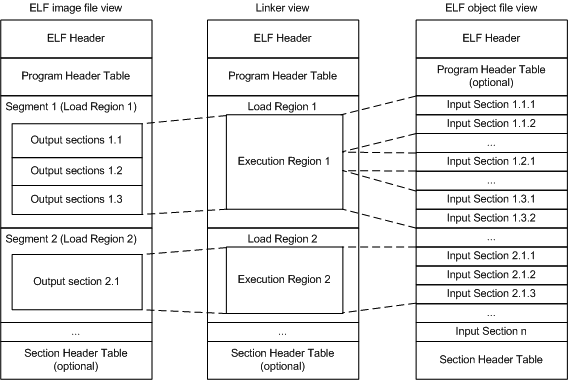
ARM ELF映像包含sections, regions, and segments,每个链接阶段都有不同的映像视图。
- Number of its constituent regions and output sections.
- Positions in memory of these regions and sections when the image is loaded.
- Positions in memory of these regions and sections when the image executes.
- ELF object file view (linker input)
-
The ELF object file view comprises包含 input sections. The ELF object file can be:
- A relocatable( 浮动的) file that holds code and data suitable for linking with other object files to create an executable or a shared object file.
- A shared object file that holds code and data.
- Linker view
-
The linker has two views for the address space of a program that become distinct in the presence of overlaid(覆盖层的存在), position-independent, and relocatable program fragments (code or data):
- The load address of a program fragment is the target address that the linker expects an external agent such as a program loader, dynamic linker, or debugger to copy the fragment from the ELF file. This might not be the address at which the fragment executes.
- The execution address of a program fragment is the target address where the linker expects the fragment to reside(属于,归于) whenever it participates(参加) in the execution of the program.
If a fragment is position-independent or relocatable, its execution address can vary during execution. - ELF image file view (linker output)
-
The ELF image file view comprises program segments and output sections:
- A load region corresponds to a program segment.
- An execution region contains one or more of the following output sections:
- RO section.
- RW section.
- XO section.
- ZI section.
One or more execution regions make up a load region.
Note
- The term root region means a region that has the same load and execution addresses.
- Load regions are equivalent to ELF segments.
3.2 Input sections, output sections, regions, and program segments
An object or image file is constructed from a hierarchy of input sections, output sections, regions, and program segments.
- Input section
-
An input section is an individual section from an input object file. It contains code, initialized data, or describes a fragment of memory that is not initialized or that must be set to zero before the image can execute. These properties are represented by attributes such as RO, RW, XO, and ZI. These attributes are used by armlink to group input sections into bigger building blocks called output sections and regions.
- Output section
-
An output section is a group of input sections that have the same RO, RW, XO, or ZI attribute, and that are placed contiguously in memory by the linker. An output section has the same attributes as its constituent input sections. Within an output section, the input sections are sorted according to the section placement rules.
- Region
-
A region contains up to four output sections depending on the contents and the number of sections with different attributes. By default, the output sections in a region are sorted according to their attributes. Any XO output section is first, followed by the RO output section, then the RW output section, and finally the ZI output section. A region typically maps onto a physical memory device, such as ROM, RAM, or peripheral. You can change the order of output sections using scatter-loading.
- Program segment
-
A program segment corresponds to a load region and contains execution regions. Program segments hold information such as text and data.
3.3 Load view and execution view of an image
Image regions are placed in the system memory map at load time. The location of the regions in memory might change during execution.
- Load view
-
Describes each image region and section in terms of the address where it is located when the image is loaded into memory, that is, the location before image execution starts.
- Execution view
-
Describes each image region and section in terms of the address where it is located during image execution.

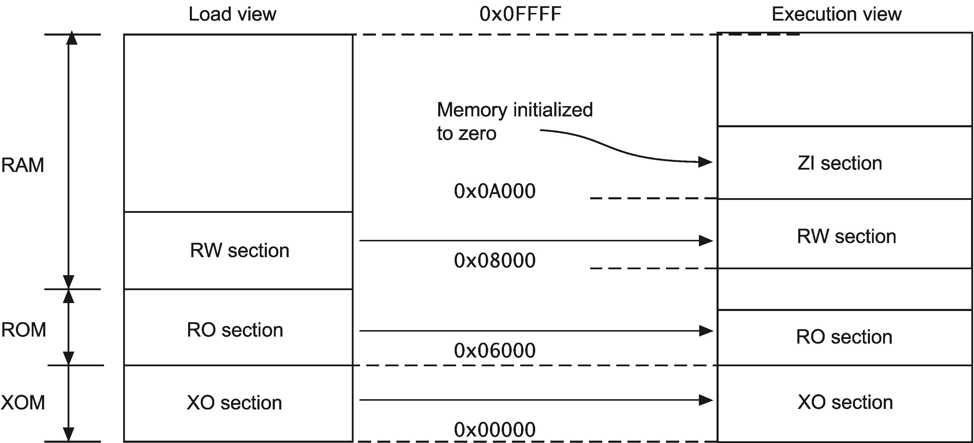
Table 3-1 Comparing load and execution views
| Load | Description | Execution | Description |
|---|---|---|---|
| Load address | The address where a section or region is loaded into memory before the image containing it starts executing. The load address of a section or a non-root region can differ from its execution address | Execution address | The address where a section or region is located while the image containing it is being executed |
| Load region | A load region describes the layout of a contiguous chunk of memory in load address space. | Execution region | An execution region describes the layout of a contiguous chunk of memory in execution address space. |
3.6 Type 1 image structure, one load region and contiguous execution regions
A Type 1 image consists of a single load region in the load view and three execution regions placed contiguously in the memory map.

armlink --ro_base 0x8000
Note
0x8000 is the default address, so you do not have to specify --ro_base for the example.Load view
Execution view
--ro_base address to specify the load and execution address of the region containing the RO output. The default address is 0x8000.--zi_base command-line option to specify the base address of a ZI execution region.Load view for images containing execute-only regions
--ro_base. The RO and RW output sections are placed consecutively and immediately after the XO section.Execution view for images containing execute-only regions
--ro_base. The RO, RW, and ZI execution regions are placed contiguously and immediately after the XO execution region.3.7 Type 2 image structure, one load region and non-contiguous execution regions
A Type 2 image consists of a single load region, and three execution regions in execution view. The RW execution region is not contiguous with the RO execution region.
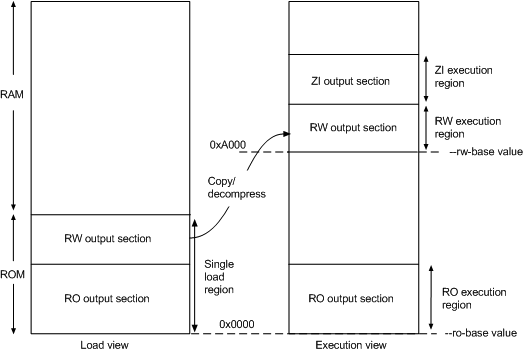
armlink --ro_base 0x0 --rw_base 0xA000
Load view
Execution view
--ro_base address to specify the load and execution address for the RO output section, and --rw_base address to specify the execution address of the RW output section. If you do not use the --ro_base option to specify the address, the default value of 0x8000 is used by armlink. For an embedded system, 0x0 is typical for the --ro_base value. If you do not use the --rw_base option to specify the address, the default is to place RW directly above RO (as in a Type 1 image).--zi_base command-line option to specify the base address of a ZI execution region.Note
Load view for images containing execute-only regions
--ro_base. The RO and RW output sections are placed consecutively and immediately after the XO section.Execution view for images containing execute-only regions
--ro_base. The RO execution region is placed contiguously and immediately after the XO execution region.--xo_base address, then the XO execution region is placed in a separate load region at the specified address.3.8 Type 3 image structure, multiple load regions and non-contiguous execution regions
A Type 3 image is similar to a Type 2 image except that the single load region is split into multiple root load regions.

armlink --split --ro_base 0x8000 --rw_base 0xE000
Load view
Execution view
--ro_baseaddress-
Instructs armlink to set the load and execution address of the region containing the RO section at a four-byte aligned
address, for example, the address of the first location in ROM. If you do not use the--ro_baseoption to specify the address, the default value of0x8000is used byarmlink. --rw_baseaddress-
Instructs armlink to set the execution address of the region containing the RW output section at a four-byte aligned
address. If this option is used with--split, this specifies both the load and execution addresses of the RW region, for example, a root region. --split-
Splits the default single load region, that contains both the RO and RW output sections, into two root load regions:
- One containing the RO output section.
- One containing the RW output section.
You can then place them separately using--ro_baseand--rw_base.
Load view for images containing XO sections
--ro_base. The RO and RW output sections are placed consecutively and immediately after the XO section.--split, then the one load region contains the XO and RO output sections, and the other contains the RW output section.Execution view for images containing XO sections
--ro_base. The RO execution region is placed contiguously and immediately after the XO execution region.--split, then the XO and RO execution regions are placed in the first load region, and the RW and ZI execution regions are placed in the second load region.--xo_base address, then the XO execution region is placed at the specified address in a separate load region from the RO execution region.3.11 Section placement with the linker
The linker places input sections in a specific order by default.
- By attribute as follows:
- Read-only code.
- Read-only data.
- Read-write code.
- Read-write data.
- Zero-initialized data.
- By input section name if they have the same attributes. Names are considered to be case-sensitive and are compared in alphabetical order using the ASCII collation sequence for characters.
- By a tie-breaker if they have the same attributes and section names. By default, it is the order that armlink processes the section. You can override this with the
FIRSTorLASTexecution region attribute.
Note
--tiebreaker=cmdline option uses a more predictable order based on the order the section appears on the command line.- One execute-only (XO) section if the execution region contains only XO sections.
- One RO section if the execution region contains read-only code or data.
- One RW section if the execution region contains read-write code or data.
- One ZI section if the execution region contains Zero-initialized data.
Note
--sort=algorithm command-line option. The linker might change the algorithm to minimize the amount of veneers generated if no algorithm is chosen.Handling unassigned sections
- If the sections must be placed at specific locations, then modify your scatter file to include specific module selectors and input section selectors as required.
- If the placement of the unassigned sections is not important, you can use one or more
.ANYmodule selectors with optional input section selectors.
Examples
LoadRegion 0x8000

{

    ExecRegion1 0x0000 0x4000

    {

        *(sections)

        *(moresections)

    }

    ExecRegion2 0x4000 0x2000

    {

        *(evenmoresections)

    }

}
3.12 Section placement with the FIRST and LAST attributes
You can make sure that a section is placed either first or last in its execution region. For example, you might want to make sure the section containing the vector table is placed first in the image.
- If you are not using scatter-loading, use the
--firstand--lastlinker command-line options to place input sections. - If you are using scatter-loading, use the attributes
FIRSTandLASTin the scatter file to mark the first and last input sections in an execution region if the placement order is important.However,FIRSTandLASTmust not violate the basic attribute sorting order. For example,FIRST RWis placed after any read-only code or read-only data.
3. Image Structure and Generation的更多相关文章
- GC那些事儿--Android内存优化第一弹
引言 接App优化之内存优化(序), 作为App优化系列中内存优化的一个小部分. 由于内存相关知识比较生涩, 内存优化中使用到的相关工具, 也有很多专有名词. 对Java内存管理, GC, Andro ...
- Android内存优化5 了解java GC 垃圾回收机制3
引言 接App优化之内存优化(序), 作为App优化系列中内存优化的一个小部分. 由于内存相关知识比较生涩, 内存优化中使用到的相关工具, 也有很多专有名词. 对Java内存管理, GC, Andro ...
- Apache Kafka: Next Generation Distributed Messaging System---reference
Introduction Apache Kafka is a distributed publish-subscribe messaging system. It was originally dev ...
- JVM Specification 9th Edition (3) Chapter 2. The Structure of the Java Virtual Machine
Chapter 2. The Structure of the Java Virtual Machine 内容列表 2.1. The class File Format (class文件的格式) 2. ...
- 1.2 the structure of a compiler
Compiler 1.2 the structure of a compiler Compiler : analysis and synthesis syntactically 语法上的 sema ...
- 《The challenge of realistic music generation: modelling raw audio at scale》论文阅读笔记
The challenge of realistic music generation: modelling raw audio at scale 作者:Deep mind三位大神 出处:NIPS ...
- 《SONG FROM PI: A MUSICALLY PLAUSIBLE NETWORK FOR POP MUSIC GENERATION》论文笔记
出处:ICLR 2017 Motivation 提出一个通用的基于RNN的pop music生成模型,在层次结构中封装了先验乐理知识(prior knowledge about how pop mus ...
- 《MIDINET: A CONVOLUTIONAL GENERATIVE ADVERSARIAL NETWORK FOR SYMBOLIC-DOMAIN MUSIC GENERATION》论文阅读笔记
出处 arXiv.org (引用量暂时只有3,too new)2017.7 SourceCode:https://github.com/RichardYang40148/MidiNet Abstrac ...
- 《MuseGAN: Multi-track Sequential Generative Adversarial Networks for Symbolic Music Generation and Accompaniment》论文阅读笔记
出处:2018 AAAI SourceCode:https://github.com/salu133445/musegan abstract: (写得不错 值得借鉴)重点阐述了生成音乐和生成图片,视频 ...
随机推荐
- 【LeetCode 18】四数之和
题目链接 [题解] 两重循环枚举[i..j]这个区间 同时规定必取nums[i]和nums[j] 那么现在的问题就变成在下标为[i..j]这个区间的数字里面找两个数字使他们的和为target-nums ...
- DNS域名服务器的搭建
父域的DNS(svr7): 可以解析父域名下保存的域名地址,即解析.tedu.cn下的域名 一.安装软件包bind.bind-chroot bind是DNS解析服务需要用到的服务软件包,bind- ...
- AcWing 143. 最大异或对 01字典树打卡
在给定的N个整数A1,A2……ANA1,A2……AN中选出两个进行xor(异或)运算,得到的结果最大是多少? 输入格式 第一行输入一个整数N. 第二行输入N个整数A1A1-ANAN. 输出格式 输出一 ...
- AntiPlug
反插件工程 #pragma once #ifndef __ENHANFUNC_H__ #define __ENHANFUNC_H__ #include <iostream> #includ ...
- error LNK2001: 无法解析的外部符号 __imp__MessageBoxA@16
错误: error LNK2001: 无法解析的外部符号 __imp__MessageBoxA@16 原因: 本来程序的编译选项选择的是:使用标准windows库,当改为在静态库中使用MFC后就出现了 ...
- dubbo使用multicast注册方式消费者无法发现服务的一种情况(我遇到的情况)
今天做dubbo测试的时候,翻出以前的代码,使用multicast广播地址的方式消费者居然无法发现服务.我的情况是因为启用了vmware虚拟机的网卡,导致了消费者无法发现服务,禁用vmware网卡后可 ...
- 2 USB标准请求
2 USB标准设备请求的结构 2.1 标准请求 bmRequestType 的D6~D5为00的请求,USB协议定义了11个标准请求(bRequest),其名字与相应的bRequest的值如下表: 表 ...
- CPUID读取有关Cache的信息
1: void cpuidTest() 2: { 3: u32 val_eax, val_ebx, val_ecx, val_edx; 4: asm("cpuid" 5: : &q ...
- swapper_pg_dir的作用
在内存系统初始化过程中,有如下代码: 1: static void __init pagetable_init(void) 2: { 3: pgd_t *pgd_base = swapper_pg_d ...
- 剑指offer——71扑克牌中的顺子
题目描述 LL今天心情特别好,因为他去买了一副扑克牌,发现里面居然有2个大王,2个小王(一副牌原本是54张^_^)...他随机从中抽出了5张牌,想测测自己的手气,看看能不能抽到顺子,如果抽到的话,他决 ...