IFA Basics
The inverted-F antenna is shown in Figure 1. While this antenna appears to be a wire antenna, after some analysis of how this antenna radiates, it is more accurately classified as an aperture(孔) antenna.
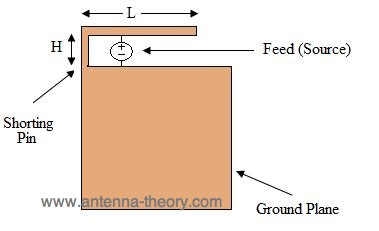
Figure1. Geometry of Inverted-F Antenna
The feed is placed from the ground plane to the upper arm of the IFA. The upper arm of the IFA has a length that is roughly a quarter of a wavelength. To the left of the feed(as shown in Figure 1), the upper arm is shorted to the ground plane. The feed is closer to the shorting pin than to the open end of the upper arm. The polarization of this antenna is vertical, and the radiation pattern is roughly donut shaped, with the axis of the donut in the vertical direction. The ground plane should be at least as wide as the IFA length(L), and the ground plane should be at least lambda/4 in height. If the height of the ground plane is smaller, the bandwidth and efficiency will decrease. The height of the IFA(H), should be a small fraction of a wavelength. The radiation properties and impedance are not a strong frunction of this parameter(H).
Because the structure somewhat resembles an inverted F, this antenna takes the name "Inverted F Antenna".
Analysis
Why does this structure radiate?Lets go back and look at the slot antenna, shown in Figure 2.

Figure 2. Geometry of Slot Antenna
The slot antenna should be a half-wavelength long for proper radiation(more generally, the perimeter of the slot antenna should be roughly one wavelength long). The way this antenna is fed(or excited by the vlogage source), the voltage at the ends of the slot(across the aperture) must be zero because of the shorting posts on either side. If the voltage is zero at the edges of the slot, then the voltage will be at a maximum a quarter-wavelength away(at the center of the slot).
Now, where is the current at a maximum? Since this antenna can also be view as a transmission line, the source basically "sees" a short circuited transmission line in either direction. We know from transmission line theory that when a transmission line is short-circuited, the voltage and current are 90 degrees out of phase. As a result, the current will be zero at the center of the slot antenna, and will be maximum on the edges. The voltage and current distributions are shown in Figure 3(note the peak voltage is assumed to be P volts, and the peak current is A Amps).

Figure 3. Voltage and Current Distribution along a Half-Wavelength Slot Antenna
The slot antenna radiates because the voltage is in-phase across the entire aperture, so that the E-field is vertical and lines up everywhere along the slot.
This also gives rise to the vertical polarization.
How does this relate to the IFA? Here is the key point: if the current at the center of the slot is zero(as shown in Figure 3), then the slot antenna can be thought of as having an open circuit at the center of the slot. Hence, if we break the slot in half, and get rid of the right side, we are left with the IFA antenna as shown in Figure 1.
Note that the IFA can support the exact same mode of radiation. That is, since the IFA has an open circuit on the right side of the feed(Figure 1), the current will be zero at that point and the voltage will be a maximum - exactly as in the slot antenna case. Hence, the IFA can be viewed as "half a slot antenna". And indeed, this is a valid model for the antenna. Hence, the IFA is classified as an aperture antenna, even though the aperture is not "closed".
Circuit model for IFA(and Slot) Antennas
For effective radiation, we need the antenna to be a good radiating structure(the currents or electric fields add up in phase), and we need to be able to get the energy down the transmission line and onto the antenna. This means we need the impedance of the antenna to be roughly 50 Ohms ( typically ). To accomplish this, it is desirable to have the reactive component of the impedance (imaginary part) to be zero. For the IFA or slot antenna, note that the feed sees a shorted transmission line a small fraction of a wavelength creates an inductive reactive component. A shorted transmission line that is a small fraction of a wavelength creates an inductive reactive component. Similarly, the open circuit on the IFA creates a capacitance to the right of the feed. The feed location is chosen to "balance out" the capacitance (to the right of the feed) and the inductance (to the left of the feed as shown in Figure 1). The inductance and capacitance cancel out, leaving just the radiation resistance. An equivalent circuit model of the IFA is shown in Figure 4.

Figure 4. Circuit Model for IFA Antenna.
Note that for the slot antenna of Figure 2, the shot-circuit to the right of the feed still creates a capacitance, because the length of the slot to the right of the feed is larger than a quarter-wavelength.
In regards to the real part of the impedance for an IFA or slot antenna, note that if the slot antenna was fed at the center of the slot(where the voltage is maximum and the current is zero----Z=V/I), the impedance would be practically infinite, so that the antenna would not radiate. By moving the feed away from the center for a slot, this also allows the current to decrease from zero, which allows the impedance to drop to a more desirable value. The same is true on the IFA antenna. Hence, the feed location is a critical factor in designing an IFA or slot. A good location for the feed can easily be obtained experimentally during an antenna design.
Examples of IFAs in the Real World
IFAs are commonly used in mobile phones due to their small size ( quarter-wavelength ). An example of several IFAs in mobile phone can be seen clearly on the Palm Pre. These antennas are visible once the back cover is removed, shown in Figure 5:

Figure 5. Palm Pre Antennas viewable by Removing Back Cover
The yellow strip on the left side of the Palm Antenna is the GPS antenna, which is an IFA. Since the GPS frequency is 1.575 GHz, a quarter wavelength is about 1.87 inches (4.75 cm). This is roughly the length of the IFA in the actual product (it is shortened for proper tuning).
Two other antennas are visible in Figure 5. In the upper right side, there is the diversity cell antenna, which is a receive only antenna (does not transmit). At the bottom of the device is a dual band IFA. This antenna is the transmit/receive cell antenna, which should operate at the 900 MHz and 1800 MHz bands. To do this, the antenna engineers made an IFA for the high band (1800 MHz), which is the shorter arm shown in Figure 5. Using the same feed and shorting pin, they branched off another arm for the low band (the longer arm, that is wrapped around itself somewhat). Because the designers had limited space (which is a big challenge in mobile phone antenna development), they wrapped the IFA around itself on the edges. By doing this, they were able to obtaion the required length for a 900 MHz IFA. However, by wrapping the antenna around itself, the bandwidth and radiation efficiency decrease.
In summary, the IFA antenna is useful because of its small size and easy construction.
来源:http://www.antenna-theory.com/antennas/aperture/ifa.php
IFA Basics的更多相关文章
- Assembler : The Basics In Reversing
Assembler : The Basics In Reversing Indeed: the basics!! This is all far from complete but covers ab ...
- The Basics of 3D Printing in 2015 - from someone with 16 WHOLE HOURS' experience
全文转载自 Scott Hanselman的博文. I bought a 3D printer on Friday, specifically a Printrbot Simple Metal fro ...
- Cadence UVM基础视频介绍(UVM SV Basics)
Cadence关于UVM的简单介绍,包括UVM的各个方面.有中文和英文两种版本. UVM SV Basics 1 – Introduction UVM SV Basics 2 – DUT Exampl ...
- C basics
C 日记目录 C basics ................ writing Numeration storage , structor space assigning pointer, a ...
- Xperf Basics: Recording a Trace(转)
http://randomascii.wordpress.com/2011/08/18/xperf-basics-recording-a-trace/ This post is obsolete ...
- Xperf Analysis Basics(转)
FQ不易,转载 http://randomascii.wordpress.com/2011/08/23/xperf-analysis-basics/ I started writing a des ...
- Radio Basics for RFID
Radio Basics for RFID The following is excerpted from Chapter 3: Radio Basics for UHF RFID from the ...
- 【IOS笔记】View Controller Basics
View Controller Basics 视图控制器基础 Apps running on iOS–based devices have a limited amount of screen s ...
- NSInvocation Basics
In this article I'm going to cover the basics and usages of NSInvocation. What is NSInvocation? Appl ...
随机推荐
- Beaglebone Black教程Beaglebone Black的引脚分配
Beaglebone Black教程Beaglebone Black的引脚分配 Beaglebone Black的引脚分配 绝大多数的微型开发平台都提供了一些称为GPIO的输入输出端口.这些端口可以让 ...
- BZOJ 2157 旅游(树链剖分+线段树)
[题目链接] http://www.lydsy.com/JudgeOnline/problem.php?id=2157 [题目大意] 支持修改边,链上查询最大值最小值总和,以及链上求相反数 [题解] ...
- python3-开发进阶Django-CBV和FBV及CBV的源码分析
一.CBV和FBV 全称应该是class base views 和function base views理解起来应该就是基于类的视图函数和基于函数的视图函数 FBV 应该是我目前最常用的一种方式了,就 ...
- 协程和IO模型
协程 1.什么是协程 单线程实现并发 在应用程序里控制多个任务的切换+保存状态 优点: 应用程序级别速度要远远高于操作系统的切换 缺点: 多个任务一旦有一个阻塞没有切,整个线程都阻塞在原地 该线程内的 ...
- 修改request的parameter的几种方式(转载)
转载地址:https://blog.csdn.net/xieyuooo/article/details/8447301
- 关于abstract class 和 interface
1.abstract class 在 Java 语言中表示的是一种继承关系,一个类只能使用一次继承关系.但是,一个类却可以实现多个interface. 2.在abstract class 中可以有自己 ...
- Learning Note: SQL Server VS Oracle–Database architecture
http://www.sqlpanda.com/2013/07/learning-note-sql-server-vs.html This is my learning note base on t ...
- java 多线程处理一个list的集合
原文:http://blog.csdn.net/jenny8080/article/details/52100312 import java.util.ArrayList; import java.u ...
- oracle如何查询哪个表数据量大
- python numpy学习记录
numpy是一个python和矩阵相关的库,在机器学习中非常有用,记录下numpy的基本用法 numpy的数组类叫做ndarray也叫做数组,跟python标准库中的array.array不同,后者只 ...