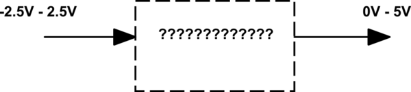
Level shifting a +/- 2.5V signal to 0 - 5V
Google : Op-Amp Level Shifter
Level shifting a +/- 2.5V signal to 0 - 5V
I have a front end module that generates an (ECG) signal that varies from +/-2.5 V. I want to shift this signal to 0 - 5V. What is the best way to do this?
First thing to try is a simple resistor adder, without opamp.
But it's clear that this won't work here:
a resistor adder always attenuates the signal, and we need a ×1 amplification.
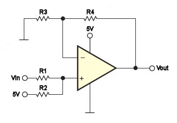
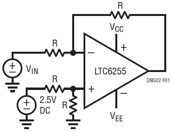
This is a non-inverting summing amplifier. You would think that we simply have to add 2.5 V, but do you have that? I'm assuming you have 5 V, so let's use that and see where it gets us. If we have -2.5 V on the Vin input the non-inverting input should be zero if you want 0 V out, regardless of the values of R3 and R4. So R1 and R2 form a voltage divider, and R2 should be twice R1 to get the 0 V.
Next we have to find the amplification, which is determined by R3 and R4:
AV = ( R3+R4 ) / R3
If we have 2.5 V on the Vin input and with R2 = 2 ×R1 we get 3.33 V on the non-inverting input of the opamp. To make that 5 V out we have to amplify by 1.5, so R3 must be twice R4.
We could use the following values:
R1 = 10 kΩ
R2 = 20 kΩ
R3 = 20 kΩ
R4 = 10 kΩ
You'll need an RRIO (Rail-to-Rail I/O) opamp if you want to power if from a single 5 V supply.
Here is one way to do it:
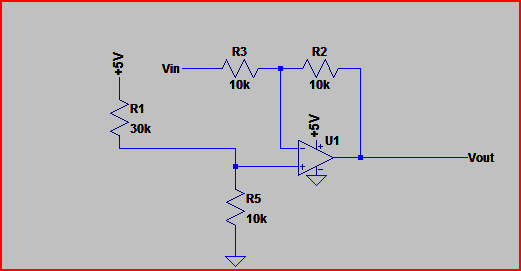
The resistive divider supplies 1.25V to the non-inverting input.
This can be replaced by a dedicated voltage reference if desired. You will need a rail to rail output opamp.
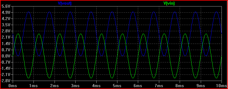
Here is a simulation:
Note the input impedance is defined by R3, so you may need to increase this (and R2 by the same) or buffer if the source is high impedance.
Also note that the output is inverting.
Here's a non-inverting method for reference also:
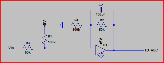
And the simulation (the "to_adc" is the output voltage):
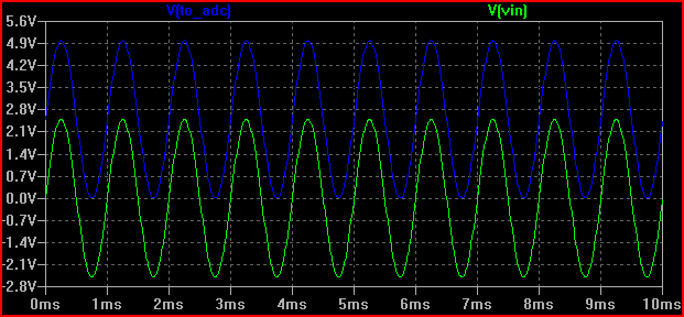
The above non-inverting circuit is a bit like your summing amplifier.
The summing amp you show has a problem though, the inverting gain resistors shown will not correct for the divider.
It needs (R1 + R2) for the feedback resistor.
So gain equals ((R1 + R2) / R2) + 1.
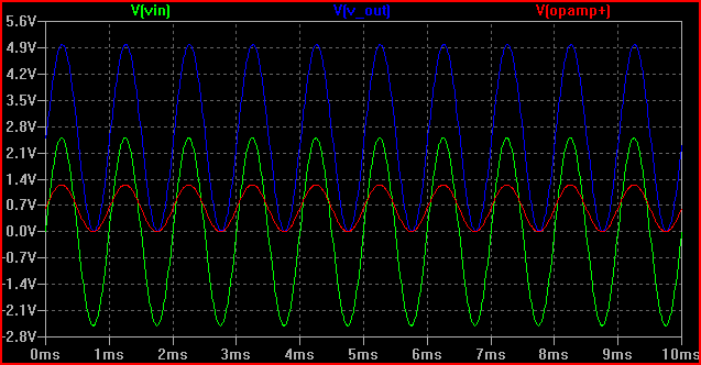
Here is an example of how it should look (the a and b suffixes are just to keep SPICE happy):
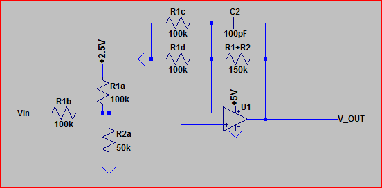
In the simulation you can see the opamp +IN swings from 0V to 1.25V,
so it needs a gain of 4 to output 0V to 5V.
Since R1c and R1d are in parallel, we get 50k. So (150k / 50k) + 1 = 4.
I'm curious, how did you size C2?
I didn't actually size it for this particular question, it's a remnant from a previous schematic
I adjusted for this answer (I left it in as it's always a good idea t
o have a small cap across Rf to prevent oscillation, but didn't want to go into more detail in that area)
However, as shown the bandwidth would be 1 / (2pi * C2 * (R1+R2)) -> 1 / (6.28 * 100e-12 * 150e3) = ~10.6kHz.
For an ECG, the bandwidth could be reduced plenty more.
Non-Inverting Op-Amp Level Shifter
A common engineering task is to convert a positive to negative signal into a range suitable for a single supply ADC.
This circuit will convert a +/-5V signal into a 0 to 3.3V signal so that it can be sampled by an ADC on a 3.3V microprocessor.
Check out our Op-Amp Resistor-Calculator.
Equations:
A = (R4/R1) x (R1+R2)/(R3+R4)
If R1= R3, and R2=R4, then
A= (R4/R1)
We want to convert a 10Vpp signal to a 3.3V signal so the gain should be 1/3. We can choose R4 to be 33K and R1 to be 100K.
Now we need to choose the positive offset such that the signal is centered at 1.6V.
The gain off the offset voltage is:
Aoffset= (R2+R1)/R1 x R3/(R3+R4) = R3/R1.
For the previous resistor values, the gain is 1 since R3=R1, and so we use an offset voltage of 1.6V.
Single-Supply Op Amp Forms Noninverting Level Shifter
Abstract: Single-supply circuitry saves space and cost, but audio and video are usually referenced to ground, which requires two op amps and a negative rail. This circuit, however, uses only one op amp (MAX4380) to level-shift a ground-referenced signal while operating on a single supply voltage.
A similar version of this article appeared in the May 5, 2010 issue of Electronic Design magazine.
As portable battery-operated devices continue to shrink in size while adding functionality, their PCB real estate becomes increasingly valuable. Single-supply circuitry can help by saving space and cost. Adding audio or video, however, can pose a problem because those signals are usually referenced to ground.
Most single-supply ICs must be configured for signals above ground, so it's necessary to shift most audio or video input signals to an appropriate level above ground. For video, you must also preserve the signal polarity. Unfortunately, however, operation on a single supply voltage while preserving signal polarity is impossible with traditional op-amp level shifters, which demand two op amps and a negative rail.
The single op-amp circuit of Figure 1 level shifts a ground-referenced signal while operating on a single supply voltage. The op amp's noninverting summing configuration creates the level-shifted output by summing a reference voltage with the input signal. A standard potentiometer with a bypass capacitor sets the reference voltage in this case, but any voltage reference capable of providing enough bias current for the op amp and summing resistors will suffice.
Figure 1. This noninverting level shifter operates on a single supply voltage, with one op amp.
This example also includes the 75Ω termination resistors required in a standard video application.
Accordingly, the op amp shown features a small footprint plus the wide bandwidth necessary for video.
Figure 2 shows the circuit in action, shifting a 10MHz ground-referenced input signal (bottom trace, blue) by +1.5V (top trace, orange).
Figure 2. The Figure 1 circuit shifts this ground-referenced 10MHz signal (bottom trace) by +1.5V (top trace).
A Single-Ended Op Amp Used as a Level Shifter
Some ideal op amp configurations assume that the feedback resistors exhibit perfect matching.
In practice, resistor non-idealities can affect various circuit parameters such as common mode rejection ratio (CMRR),
harmonic distortion and stability. For instance, as shown in Figure 1, a single-ended amplifier configured
to level-shift a ground-referenced signal to a common mode of 2.5V needs a good CMRR.
Assuming 34dB CMRR and no input signal, this 2.5V level shifter exhibits an output offset of 50mV,
which can even overwhelm the LSB and offset errors of 12-bit ADCs and drivers.
Offset an input voltage of -2.5V - 2.5V to 0V - 5V?
This question already has an answer here:
I have a circuit input which provides a voltage range of negative 2.5 volts to positive 2.5 volts. How do I change this so the output voltage is 0 - 5 volts?
There are several ways to do this, for instance using an opamp to sum 2.5V to your signal:
This is an inverting summing amplifier, so for R1=R2=R4, the output would be Vo=−(VAC+VDC)
If you want to keep the phase of the signal, a non-inverting summing amplifier would be like this:
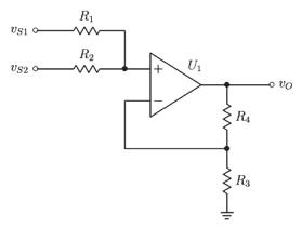
In this, R3,R4 control the gain of the amplifier, and R1,R2 act as a resistor divider.
Analysing this, we get that the output is
Vo = Vinop * ( (R3+R4) / R3), and from the resistor divider
Vinop = ( Vs1 * R2 + Vs2 * R1 ) / ( R1+R2 )
If we make R2=2 R1 we get Vinop= ( 2Vs1+Vs2 ) / 3.
Substituting this in the first output equation, and making the gain 2/3 by choosing R3=2R4,
then the final output will be the desired Vo=Vs1 + Vs2/2, being Vs1 the -2.5V to 2.5V AC input signal and Vs2=5V in this case.
In page 6 here you can also find a few different examples to offset signals using opamps:
http://www.ti.com/ww/en/bobpease/assets/AN-31.pdf
Level shifting a +/- 2.5V signal to 0 - 5V的更多相关文章
- Non-Inverting Level Shifter : +/-5V signal into a 0 to 3.3V
http://electronicdesign.com/boards/non-inverting-level-shifter-requires-only-one-op-amp-one-supply-v ...
- XBee Level Shifting
http://www.faludi.com/bwsn/xbee-level-shifting/ The XBee communication (RX/TX) pins definitely opera ...
- 实用的4~20mA输入/0~5V输出的I/V转换电路(转)
源: 实用的4~20mA输入/0~5V输出的I/V转换电路
- 4~20mA转0~5V
RCV420是一种精密的I/V转换电路,也是目前最佳的4-20mA转换0-5V的电路方案,有商用级(0℃-70℃)和工业级(-25℃-+85℃)供你选购 301欧姆为精度1%. RCV420运行40m ...
- 1.5V升5V芯片,1.5V升5V电路图规格书
常用的 5号,7号等 1.5V 干电池满电电压在 1.6V 左右,干电池输出耗电电压在 1V.适用PW5100,在 0.9V 时还能输出,彻底榨干干电池的电量. 1.5V 升5V 的芯片:PW5100 ...
- ili9325--LCD寄存器配置研究
2011-06-22 22:18:12 自己根据ili9325的规格书编写驱动.发现LCD屏没显示.于是怀疑是某些寄存器设置错误.要调试的话最好还是先熟悉寄存器的作用,调试的时候只要看到现象就能分析了 ...
- 集成多种协议、用于 USB-A 和 TYPE-C 双端口输出的快充协议芯片IP2726
1. 特性 支持 1A1C 支持 USB-A 和 TYPE-C 双端口输出 单口输出支持全部快充协议 双口同时插入时降压到 5V 快充规格 集成 QC2.0/QC3.0/QC4/QC4+输 ...
- 集成 12 种协议、可于 USBC 端口的快充协议芯片IP2188
1. 特性 支持 12 种 USB 端口快充协议 支持 USB TypeC PD2.0/PD3.0/PPS DFP 协议 支持多种充电协议(QC3.0/QC2.0,FCP,SCP, AFC,MT ...
- 5V and 3V Level Translators
http://www.daycounter.com/Circuits/Level-Translators/Level-Translators.phtml Interfacing 5V and 3V l ...
随机推荐
- 【实(dou)力(bi)首(mai)发(meng)】第四次CCF软件能力认证题解
这次的题总体上相对前三次偏简单.由于实力有限,就分析前四题. 试题编号: 201503-1 试题名称: 图像旋转 时间限制: 5.0s 内存限制: 256.0MB 问题 ...
- 返回绝对值--Math.Abs 方法
Math.abs() 返回指定数字的绝对值.
- 统计学习方法笔记 Logistic regression
logistic distribution 设X是连续随机变量,X服从逻辑斯谛分布是指X具有下列分布函数和密度函数: 式中,μ为位置参数,γ>0为形状参数. 密度函数是脉冲函数 分布函数是一条S ...
- 浅谈TCP/IP网络编程中socket的行为
我认为,想要熟练掌握Linux下的TCP/IP网络编程,至少有三个层面的知识需要熟悉: 1. TCP/IP协议(如连接的建立和终止.重传和确认.滑动窗口和拥塞控制等等) 2. Socket I/O系统 ...
- Faster RNNLM (HS/NCE) toolkit
https://github.com/kjw0612/awesome-rnn Faster Recurrent Neural Network Language Modeling Toolkit wit ...
- try catch finally return之间的关系
一.try catch finally return之间的关系: 正在写dsoFramer的时候,同事突然说面试的时候问的一个问题,catch和return那个先执行,我瞬间迷茫了,然后整理了整理,稍 ...
- [原]Jenkins(一)---我理解的jenkins是这样的
/** * lihaibo * 文章内容都是根据自己工作情况实践得出. *版权声明:本博客欢迎转发,但请保留原作者信息! http://www.cnblogs.com/horizonli/p/5330 ...
- 2006Jam的计数法
题目描述 Description Jam是个喜欢标新立异的科学怪人.他不使用阿拉伯数字计数,而是使用小写英文字母计数,他觉得这样做,会使世界更加丰富多彩.在他的计数法中,每个数字的位数都是相同的(使用 ...
- 递归获取XML元素
看到的一道题,用递归获取XML元素.... static void Main(string[] args) { string xmlContent = @"<FileSystem> ...
- Dynamic CRM 2013学习笔记(四十五)修改实体及字段的前缀(不用new_开头)
最近做一个升级的CRM项目,为了区分哪些是新增的,所以决定用一个新的前缀来定义实体及新加的字段.之前用的是new_开头,现在改成tm_开头. 原来只要是新建实体或字段都是new_开头: 1. ...