防火墙安全区域及安全策略配置
一、学习目的
- 掌握防火墙安全区域的配置方法
- 掌握安全策略的配置方法
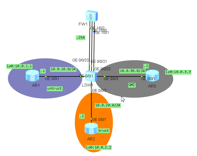
二、拓扑图
三、场景
你是公司的网络管理员。公司总部的网络分成了三个区域,包括内部区域(trust),外部区域(untrust)和服务器区域(DMZ)。你设计通过防火墙来实现对数据的控制,确保公司内部网络安全,并通过DMZ区域对外网提供服务器。
四、学习任务
步骤一、登陆防火墙
An initial password is required for the first login via the console.
Set a password and keep it safe. Otherwise you will not be able to login via the console.
Please configure the login password (8-16)
Enter Password:admin@123
Warning: The authentication mode was changed to password authentication and the user level was changed to 15 on con0 at the first user login.
Warning: There is a risk on the user-interface which you login through. Please change the configuration of the user-interface as soon as possible.
*************************************************************************
* Copyright (C) 2014-2015 Huawei Technologies Co., Ltd. *
* All rights reserved. *
* Without the owner's prior written consent, *
* no decompiling or reverse-engineering shall be allowed. *
*************************************************************************
<USG6000V1>
步骤二、根据拓扑图对设备进行基本配置与IP编址
给路由器和防火墙配置地址,并配置静态路由,在交换机上配置vlan
配置R1:
sys
sysname R1
interface GigabitEthernet 0/0/1
ip add 10.0.10.1 24
int lo0
ip add 10.0.1.1 24
ip route-static 0.0.0.0 0.0.0.0 10.0.10.254
配置R2:
sys
sysname R2
interface g0/0/1
ip address 10.0.20.1 24
int LoopBack0
ip add 10.0.2.2 24
ip route-static 0.0.0.0 0.0.0.0 10.0.20.254
[R2]interface g0/0/1
[R2-GigabitEthernet0/0/1]ip address 10.0.20.1 24
[R2-GigabitEthernet0/0/1]int LoopBack0
[R2-LoopBack0]ip add 10.0.2.2 24
[R2-LoopBack0]ip route-static 0.0.0.0 0.0.0.0 10.0.20.254
[R2]dis ip int br
*down: administratively down
^down: standby
(l): loopback
(s): spoofing
The number of interface that is UP in Physical is 3
The number of interface that is DOWN in Physical is 2
The number of interface that is UP in Protocol is 3
The number of interface that is DOWN in Protocol is 2
Interface IP Address/Mask Physical Protocol
GigabitEthernet0/0/0 unassigned down down
GigabitEthernet0/0/1 10.0.20.1/24 up up
GigabitEthernet0/0/2 unassigned down down
LoopBack0 10.0.2.2/24 up up(s)
NULL0 unassigned up up(s)
[R2]dis ip rou
[R2]dis ip routing-table
Route Flags: R - relay, D - download to fib
------------------------------------------------------------------------------
Routing Tables: Public
Destinations : 11 Routes : 11
Destination/Mask Proto Pre Cost Flags NextHop Interface
0.0.0.0/0 Static 60 0 RD 10.0.20.254 GigabitEthernet0/0/1
10.0.2.0/24 Direct 0 0 D 10.0.2.2 LoopBack0
10.0.2.2/32 Direct 0 0 D 127.0.0.1 LoopBack0
10.0.2.255/32 Direct 0 0 D 127.0.0.1 LoopBack0
10.0.20.0/24 Direct 0 0 D 10.0.20.1 GigabitEthernet0/0/1
10.0.20.1/32 Direct 0 0 D 127.0.0.1 GigabitEthernet0/0/1
10.0.20.255/32 Direct 0 0 D 127.0.0.1 GigabitEthernet0/0/1
127.0.0.0/8 Direct 0 0 D 127.0.0.1 InLoopBack0
127.0.0.1/32 Direct 0 0 D 127.0.0.1 InLoopBack0
127.255.255.255/32 Direct 0 0 D 127.0.0.1 InLoopBack0
255.255.255.255/32 Direct 0 0 D 127.0.0.1 InLoopBack0
配置R3:
<R3>sys
Enter system view, return user view with Ctrl+Z.
[R3]sysname R3
[R3]int g0/0/1
[R3-GigabitEthernet0/0/1]ip add 10.0.30.1 24
Mar 14 2018 23:27:26-08:00 R3 %%01IFNET/4/LINK_STATE(l)[0]:The line protocol IP on the interface GigabitEthernet0/0/1 has entered the UP state. int LoopBack0
[R3-GigabitEthernet0/0/1]
[R3-LoopBack0]ip add 10.0.3.3 24
[R3-LoopBack0]quit
[R3]ip route-static 0.0.0.0 0.0.0.0 10.0.30.254
防火墙默认会启用GigabitEthernet0/0/0接口的IP地址,为避免干扰可以删除。
在FW上配置明确的静态路由,实现三个loopback0接口网段之间路由畅通
FW1配置IP和路由如下:
sys
sysname FW1
int g0/0/0
undo ip address
quit
int g1/0/0
ip add 10.0.10.254 24
int g1/0/1
ip add 10.0.20.254 24
int g1/0/2
ip add 10.0.30.254 24
ip route-static 10.0.1.0 24 10.0.10.1
ip route-static 10.0.2.0 24 10.0.20.1
ip route-static 10.0.3.0 24 10.0.30.1
交换机上需要按照需求定义VLAN
交换机上的配置如下:
sys
sysname SW1
vlan batch 10 20 30
int g0/0/1
port link-type access
port default vlan 10
int g0/0/21
port link-type access
port default vlan 10
int g0/0/2
port link-type access
port default vlan 20
int g0/0/22
port link-type access
port default vlan 20
int g0/0/3
port link-type access
port default vlan 30
int g0/0/23
port link-type access
port default vlan 30
步骤三、配置防火墙区域
防火墙上默认有四个区域分别是:local、trust、untrust、dmz
实验中我们使用到trust、untrust、dmz三个区域,分别将对应接口加入各安全区域,由于默认配置将
g0/0/0加入了trust区域为避免干扰,将其删除;
FW1上配置脚本如下:
sys
firewall zone dmz
add interface g1/0/2
quit
firewall zone trust
add interface g1/0/1
undo add interface g0/0/0
quit
firewall zone untrust
add interface g1/0/0
quit
检查各接口所在的区域:
[FW1]dis zone interface
local
interface of the zone is (0):
trust
interface of the zone is (1):
GigabitEthernet1/0/1
#
untrust
interface of the zone is (1):
GigabitEthernet1/0/0
#
dmz
interface of the zone is (1):
GigabitEthernet1/0/2
#
可以看到三个接口已经被划分到相应的区域内,默认情况 下不同区域是不可互通的,因此,此时各路由器之间流量是无法通过的,需要配置区域间的安全策略放行允许通过的流量
步骤四、配置安全策略
USG6000默认情况下只有0口是可以允许所有服务的。那么如果想在其他端口开启相应的服务,需要在相应端口下面输入相应命令
3.1、配置允许从local ping通trust区域
配置前测试从local区域到trust区域连通性:
[FW1-policy-security]ping 10.0.20.1
PING 10.0.20.1: 56 data bytes, press CTRL_C to break
Request time out
Request time out
Request time out
Request time out
Request time out
--- 10.0.20.1 ping statistics ---
5 packet(s) transmitted
0 packet(s) received
100.00% packet loss
配置安全策略脚本:
sys
security-policy
rule name lo_to_tr
source-zone local
destination-zone trust
source-address 10.0.20.0 mask 255.255.255.0
action permit
quit
检查验证:
[FW1-policy-security]dis this
#
security-policy
rule name lo_to_tr
source-zone local
destination-zone trust
source-address 10.0.20.0 24
action permit
#
return
[FW1-policy-security]
[FW1-policy-security]
[FW1-policy-security]ping 10.0.20.1
PING 10.0.20.1: 56 data bytes, press CTRL_C to break
Reply from 10.0.20.1: bytes=56 Sequence=1 ttl=255 time=27 ms
Reply from 10.0.20.1: bytes=56 Sequence=2 ttl=255 time=43 ms
Mar 15 2018 12:21:21 FW1 DS/4/DATASYNC_CFGCHANGE:OID 1.3.6.1.4.1.2011.5.25.191.3.1 configurations have been changed. The current change number is 49, the change loop count is 0, and the maximum number of records is 4095.
Reply from 10.0.20.1: bytes=56 Sequence=3 ttl=255 time=40 ms
Reply from 10.0.20.1: bytes=56 Sequence=4 ttl=255 time=40 ms
Reply from 10.0.20.1: bytes=56 Sequence=5 ttl=255 time=43 ms
--- 10.0.20.1 ping statistics ---
5 packet(s) transmitted
5 packet(s) received
0.00% packet loss
round-trip min/avg/max = 27/38/43 ms
3.2、配置策略允许trust区域能ping通防火墙本地
配置前从trust区域ping防火墙:
[R2]ping 10.0.20.254
PING 10.0.20.254: 56 data bytes, press CTRL_C to break
Request time out
Request time out
Request time out
Request time out
Request time out
--- 10.0.20.254 ping statistics ---
5 packet(s) transmitted
0 packet(s) received
100.00% packet loss
流量不通
如何配置才能通呢?
如下:
interface g1/0/1
service-manage ping permit
测试OK:
[R2]ping 10.0.20.254
PING 10.0.20.254: 56 data bytes, press CTRL_C to break
Reply from 10.0.20.254: bytes=56 Sequence=1 ttl=255 time=30 ms
Reply from 10.0.20.254: bytes=56 Sequence=2 ttl=255 time=30 ms
Reply from 10.0.20.254: bytes=56 Sequence=3 ttl=255 time=50 ms
Reply from 10.0.20.254: bytes=56 Sequence=4 ttl=255 time=30 ms
Reply from 10.0.20.254: bytes=56 Sequence=5 ttl=255 time=50 ms
--- 10.0.20.254 ping statistics ---
5 packet(s) transmitted
5 packet(s) received
0.00% packet loss
round-trip min/avg/max = 30/38/50 ms
3.3、配置从trust区域的网段10.0.2.0和10.0.20.0发往untrust区域的数据包被放行,、
配置脚本如下:
sys
security-policy
rule name tr_to_un
source-zone trust
destination-zone untrust
source-address 10.0.2.0 24
source-address 10.0.20.0 24
action permit
验证结果:
[FW1]dis security-policy rule tr_to_un
(1 times matched)
rule name tr_to_un
source-zone trust
destination-zone untrust
source-address 10.0.2.0 24
source-address 10.0.20.0 24
action permit
[R2]ping -a 10.0.2.2 10.0.1.1
PING 10.0.1.1: 56 data bytes, press CTRL_C to break
Reply from 10.0.1.1: bytes=56 Sequence=1 ttl=254 time=60 ms
Reply from 10.0.1.1: bytes=56 Sequence=2 ttl=254 time=80 ms
Reply from 10.0.1.1: bytes=56 Sequence=3 ttl=254 time=90 ms
Reply from 10.0.1.1: bytes=56 Sequence=4 ttl=254 time=90 ms
Reply from 10.0.1.1: bytes=56 Sequence=5 ttl=254 time=70 ms
--- 10.0.1.1 ping statistics ---
5 packet(s) transmitted
5 packet(s) received
0.00% packet loss
round-trip min/avg/max = 60/78/90 ms
3.3、 配置从untrust区域发往DMZ目标服务器10.0.3.3的telnet和FTP请求被放行
配置脚本如下:
sys
security-policy
rule name un_to_dmz
source-zone untrust
destination-zone dmz
destination-address 10.0.3.3 32
service telnet
service ftp
service icmp
action permit
验证:
<R1>ping 10.0.3.3
PING 10.0.3.3: 56 data bytes, press CTRL_C to break
Reply from 10.0.3.3: bytes=56 Sequence=1 ttl=254 time=100 ms
Reply from 10.0.3.3: bytes=56 Sequence=2 ttl=254 time=80 ms
Reply from 10.0.3.3: bytes=56 Sequence=3 ttl=254 time=70 ms
Reply from 10.0.3.3: bytes=56 Sequence=4 ttl=254 time=70 ms
Reply from 10.0.3.3: bytes=56 Sequence=5 ttl=254 time=70 ms
--- 10.0.3.3 ping statistics ---
5 packet(s) transmitted
5 packet(s) received
0.00% packet loss
round-trip min/avg/max = 70/78/100 ms
<R1>tel
<R1>telnet 10.0.3.3
Press CTRL_] to quit telnet mode
Trying 10.0.3.3 ...
Connected to 10.0.3.3 ...
Login authentication
Username:zhi
Password:
-----------------------------------------------------------------------------
User last login information:
-----------------------------------------------------------------------------
Access Type: Telnet
IP-Address : 10.0.10.1
Time : 2018-03-15 21:08:28-08:00
-----------------------------------------------------------------------------
- 华为HCNP实验 DHCP配置
HCNP实验 DHCP配置 学习目的 1.掌握ip pool的配置方法2.掌握DHCP服务器的配置方法3.掌握DHCP客户端的配置方法4.掌握DHCP中继的配置方法5.掌握DHCP Snooping的 ...
- 华为HCIP实验--OSPF单区域
场景:你是公司的网络管理员.现在公司的网络中有三台ARG3路由器,通过以太网实现相互的连通.在以太网这样的广播式多路访问网络上,可能存在安全隐患,所有你选择采用OSPF区域认证的方法来避免恶意的路由攻 ...
- ensp练习:防火墙安全策略配置
一.实验目的:1. 了解华为防火墙安全策略.2. 掌握华为防火墙安全策略的配置.二.实验仪器:计算机.华为ensp模拟器.华为防火墙三.实验内容:在这里插入图片描述根据网络拓扑图如上(交换机不需要配置 ...
- 自学华为IoT物联网_10 IoT联接管理平台配置及开发实验1
点击返回自学华为IoT物流网 自学华为IoT物联网_10 IoT联接管理平台配置及开发实验1 实验1:OceanConnect平台实验 通过基本的编程操作与配置,帮助读者熟悉O ...
- 华为hcnp r&s考试一共有三门,R&S-IERS,R&S-IENP,R&S-IEEP
大纲1.HCNP-R&S-IEEP V2.0考试大纲 考试内容:HCNP-R&S-IEEP考试覆盖对企业网络的规划.设计.实施.维护.排障.优化以及网络割接等. 知识点: 网络规划:1 ...
- H3C防火墙开启区域间互访
配置ip和路由以及将端口放至Untrust之后,外网还是不通,需要以下命令 interzone policy default by-priority 或者下面: security-zone intra ...
- 华为eNSP的防火墙(USG6000V)如何使用Web界面登入
文章目录 华为eNSP的防火墙(USG6000V)如何使用Web界面登入 前言 一.使用步骤 1.导入USG6000V的镜像包 总结 前言 在华为的eNSP的模拟器上如何使用Web界面去管理与使用模拟 ...
- 交换机 路由器 防火墙asa 安全访问、配置 方式
这里交换机 路由器 暂时统称为 网络设备 我们一般管理网络设备采用的几种方法 一般来说,可以用5种方式来设置路由器: 1. Console口接终端或运行终端仿真软件的微机(第一次配置要使用此方式) ...
- OSPF多区域原理与配置
OSPF多区域原理与配置 目录 一.OSPF多区域生成 1.1.生成OSPF多区域的原因 二.OSPF的三种通信量 2.1.域内通信量 2.2.域间通信量 2.3.外部通信量 三.OSPF的路由器类型 ...
随机推荐
- vue-quill-editor html编辑器
在Vue项目使用quill-editor带样式编辑器(更改插入图片和视频) https://www.cnblogs.com/zhengweijie/p/7305903.html vue-quil ...
- jQuery 学习笔记(jQuery: The Return Flight)
第一课. ajax:$.ajax(url[, settings]) 练习代码: $(document).ready(function() { $("#tour").on(" ...
- android LinearLayoutForListView
由于 scrollview 套 listview 会有很多问题,网上很多人用 LinearLayout 模拟 listview, 也可以设置 adapter. 很多人直接继承 BaseAdapter, ...
- MySQL事务实现原理
MySQL事务隔离级别的实现原理 知识储备 只有InnoDB支持事务,所以这里说的事务隔离级别是指InnoDB下的事务隔离级别 隔离级别 读未提交:一个事务可以读取到另一个事务未提交的修改.这会带来脏 ...
- React.js 小书 Lesson19 - 挂载阶段的组件生命周期(二)
作者:胡子大哈 原文链接:http://huziketang.com/books/react/lesson19 转载请注明出处,保留原文链接和作者信息. 这一节我们来讨论一下对于一个组件来说,cons ...
- step3: 创建jobbole爬虫
scrapy startproject Redbacktestcd Redbacktest 创建jobbole爬虫 scrapy genspider jobbole2 blog.jobbole.com ...
- MAC OS===>IntelliJ IDEA__ant__zookeeper源码编译
1:配置ant环境 https://archive.apache.org/dist/ant/binaries/ 官网下载文件 1.10.0以上需要JDK1.8以上 否则会报 Exception i ...
- 互联网轻量级框架SSM-查缺补漏第九天
简言: 第九章 Spring Ioc的概念 IoC(Inversion of Control)控制反转:比如想喝橙汁,在没有饮品店的日子,最直观的做法是买果汁机.橙汁.这是你自己“主动”创造的过程,也 ...
- Java温故而知新(10)类的加载机制
类加载是Java程序运行的第一步,研究类的加载有助于了解JVM执行过程,并指导开发者采取更有效的措施配合程序执行. 研究类加载机制的第二个目的是让程序能动态的控制类加载,比如热部署等,提高程序的灵活性 ...
- jquery+springMVC实现文件上传
此文章是基于 搭建Jquery+SpringMVC+Spring+Hibernate+MySQL平台 一. jar包介绍 1. commons-fileupload-1.3.1.jar 二. 相关程序 ...