Cisco基础(二):三层交换vlan间通信、多交换机vlan间通信、三层交换配置路由、RIP动态路由配置、三层交换配置RIP动态路由
一、三层交换vlan间通信
目标:
VLAN实现了广播域的隔离,同时也将VLAN间的通信隔离了。三层交换技术使得VLAN间可以通信。
- 通过三层交换实现VLAN间通信
方案:
为了解决了传统路由器低速、复杂所造成的网络瓶颈问题,引入了三层交换技术。它根据实际应用时的情况,灵活地在网络第二层或者第三层进行网络分段。具有三层交换功能的设备是一个带有第三层路由功能的第二层交换机。
简单地说,三层交换技术就是:二层交换技术+三层转发技术。
三层交换实现的拓扑如下图所示:

步骤:
步骤一:在连接PC的交换机上划分3个VLAN,并按图-1把PC机加入相应VLAN
tarenasw-3L (config)#vlan 2 //vlan1是默认VLAN,不需创建
tarenasw-3L (config-vlan)#vlan 3
tarenasw-3L (config-vlan)#exit
tarenasw-3L (config)#interface f0/1
tarenasw-3L (config-if)#switchport mode access
tarenasw-3L (config-if)#switchport access vlan 1
tarenasw-3L (config-if)#interface f0/2
tarenasw-3L (config-if)#switchport mode access
tarenasw-3L (config-if)#switchport access vlan 2
tarenasw-3L (config-if)#interface f0/3
tarenasw-3L (config-if)#switchport mode access
tarenasw-3L (config-if)#switchport access vlan 3
步骤二:查看划分完的VLAN信息
VLAN1是默认VLAN,不需单独创建,也不能改名。所有端口默认都在VLAN1中。
tarenasw-2L#show vlan
VLAN Name Status Ports
---- ----------------------- --------- ---------------------
1 default active Fa0/1, Fa0/4, Fa0/5, Fa0/6
Fa0/7, Fa0/8, Fa0/9, Fa0/10
Fa0/11, Fa0/12, Fa0/13, Fa0/14
Fa0/15, Fa0/16, Fa0/17, Fa0/18
Fa0/19, Fa0/20, Fa0/21, Fa0/22
Fa0/23, Fa0/24, Gig1/1, Gig1/2
2 vlan0002 active Fa0/2
3 vlan0003 active Fa0/3
步骤三:为vlan1、vlan2、vlan3分别设置管理IP并开启三层交换机路由功能
tarenasw-3L #enable
tarenasw-3L #configure terminal
tarenasw-3L (config)#ip routing //开启三层交换机路由功能
tarenasw-3L (config)#interface vlan 1
tarenasw-3L (config-if)#ip address 192.168.1.254 255.255.255.0
tarenasw-3L (config-if)#no shutdown
tarenasw-3L (config-if)#exit
tarenasw-3L (config)#interface vlan 2
tarenasw-3L (config-if)#ip address 192.168.2.254 255.255.255.0
tarenasw-3L (config-if)#no shutdown
tarenasw-3L (config-if)#exit
tarenasw-3L (config)#interface vlan 3
tarenasw-3L (config-if)#ip address 192.168.3.254 255.255.255.0
tarenasw-3L (config-if)#no shutdown
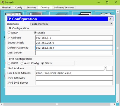
步骤四:给客户端配置IP地址并测试网络连通性如下图所示
在PC1三上测试网络连通性
PC1>ping 192.168.3.1
Pinging 192.168.3.1 with 32 bytes of data:
Reply from 192.168.3.1: bytes=32 time=11ms TTL=128
Reply from 192.168.3.1: bytes=32 time=1ms TTL=128
Reply from 192.168.3.1: bytes=32 time=1ms TTL=128
Reply from 192.168.3.1: bytes=32 time=4ms TTL=128
Ping statistics for 192.168.3.1:
Packets: Sent = 4, Received = 4, Lost = 0 (0% loss),
Approximate round trip times in milli-seconds:
Minimum = 1ms, Maximum = 11ms, Average = 4ms
二、多交换机vlan间通信
目标:
三层交换机将接入层交换机汇聚到一起后还需实现了多交换机间不同VLAN的通信。
方案:
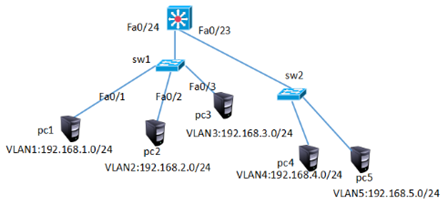
三层交换机连接其他交换机的链路需配置为中继链路,三层交换机接口配置trunk模式需先封装,sw1规划vlan1、vlan2、vlan3,Sw2规划vlan4、vlan5并按图-4给相应vlan配置对应网段的IP。
网络的拓扑结构如下图所示:
步骤:
步骤一:配置三层交换机
1)三层交换机创建vlan并配置vlan的虚端口IP并开启路由功能
Switch>enable
Switch#configure terminal
Switch(config)#vlan 2
Switch(config-vlan)#vlan 3
Switch(config-vlan)#vlan 4
Switch(config-vlan)#vlan 5
Switch(config)#interface vlan 1
Switch(config-if)#ip address 192.168.1.254 255.255.255.0
Switch(config-if)#no shutdown
Switch(config)#interface vlan 2
Switch(config-if)#ip address 192.168.2.254 255.255.255.0
Switch(config-if)#no shutdown
Switch(config)#interface vlan 3
Switch(config-if)#ip address 192.168.3.254 255.255.255.0
Switch(config-if)#no shutdown
Switch(config)#interface vlan 4
Switch(config-if)#ip address 192.168.4.254 255.255.255.0
Switch(config-if)#no shutdown
Switch(config)#interface vlan 5
Switch(config-if)#ip address 192.168.5.254 255.255.255.0
Switch(config-if)#no shutdown
Switch(config)#ip routing //开启路由功能
2)三层交换的Fa0/23、Fa0/24设置为中继链路模式
Switch(config)#interface range f0/23-24
Switch (config-if-range)#switchport trunk encapsulation dot1q
Switch (config-if-range)#switchport mode trunk
步骤二:配置二层交换机
1)Sw1创建vlan2、 vlan3并将端口加入vlan
Sw1(config)#vlan 2
Sw1(config-vlan)#vlan 3
Sw1(config)#interface fastEthernet 0/2
Sw1(config-if)#switchport access vlan 2
Sw1(config)#interface fastEthernet 0/3
Sw1(config-if)#switchport access vlan 3
Sw1(config)#interface fastEthernet 0/5
Sw1(config-if)#switchport mode trunk //连接三层交换机的接口配置为trunk模式
2)Sw2创建vlan4、 vlan5并将端口加入vlan
Sw2(config)#vlan 4
Sw2(config-vlan)#vlan 5
Sw2(config)#interface fastEthernet 0/1
Sw2(config-if)#switchport access vlan 4
Sw2(config)#interface f0/2
Sw2(config-if)#switchport access vlan 5
步骤三:按上图配置IP并测试网络的连通性
PC>ipconfig
FastEthernet0 Connection:(default port)
Link-local IPv6 Address.........: FE80::2D0:D3FF:FE2E:5D25
IP Address......................: 192.168.1.1
Subnet Mask.....................: 255.255.255.0
Default Gateway.................: 192.168.1.254
PC>ping 192.168.4.1
Pinging 192.168.4.1 with 32 bytes of data:
Reply from 192.168.4.1: bytes=32 time=0ms TTL=127
Reply from 192.168.4.1: bytes=32 time=0ms TTL=127
Reply from 192.168.4.1: bytes=32 time=0ms TTL=127
Reply from 192.168.4.1: bytes=32 time=0ms TTL=127
Ping statistics for 192.168.4.1:
Packets: Sent = 4, Received = 3, Lost = 1 (25% loss),
Approximate round trip times in milli-seconds:
Minimum = 0ms, Maximum = 0ms, Average = 0ms
PC>ping 192.168.5.1
Pinging 192.168.5.1 with 32 bytes of data:
Reply from 192.168.5.1: bytes=32 time=0ms TTL=127
Reply from 192.168.5.1: bytes=32 time=0ms TTL=127
Reply from 192.168.5.1: bytes=32 time=0ms TTL=127
Reply from 192.168.5.1: bytes=32 time=0ms TTL=127
Ping statistics for 192.168.5.1:
Packets: Sent = 4, Received = 3, Lost = 1 (25% loss),
Approximate round trip times in milli-seconds:
Minimum = 0ms, Maximum = 0ms, Average = 0ms
三、三层交换配置路由
目标:
三层交换机实现了VLAN间互通后,还要与其他网络进行通信,这样就需要有相关的路由机制。
- 交换接口配置为三层接口实现路由间通信
方案:
三层交换机既然具有三层功能,也就可以实现与路由器相似的配置。既可以把交换接口配置为三层接口,也可以在其上配置静态、动态路由。通过对三层交换机的路由配置,实现VLAN与其他网络的互通。
网络的拓扑结构如下图所示:

步骤:
步骤一:多交换机vlan通信与案例2完全一致,不再赘述
步骤二:将三层交换的Fa0/6口配置为三层路由端口,并配置IP地址
三层交换机的物理端口默认是二层端口,只具有二层特性,不能配置IP地址。把二层端口配置为三层端口后,该端口就具备路由功能了,可以配置IP地址,但同时也就关闭了其二层特性,比如不能把三层端口加入VLAN。
二层端口(交换机上的端口默认都是二层端口)默认是激活状态,那些没有使用到的端口为了安全应该手工将其禁用(shutdown);而 三层端口(路由器上的端口或是三层交换机上被配置成路由端口的端口)默认是禁用状态,在使用之前务必要将其激活(no shutdown)。
Switch(config)#interface f0/6
Switch(config-if)#no switchport
Switch(config-if)#ip address 192.168.6.1 255.255.255.0
Switch(config-if)#no shutdown
步骤三:配置路由器的端口IP地址
Switch(config)#interface f0/0
Switch(config-if)#ip address 192.168.6.2 255.255.255.0
Switch(config-if)#no shutdown
Switch(config-if)#interface f0/1
Switch(config-if)#ip address 192.168.7.254 255.255.255.0
Switch(config-if)#no shutdown
步骤四:在三层交换机上配置静态路由,以便VLAN内主机可以与外界网络互联
Switch(config)#ip route 192.168.7.0 255.255.255.0 192.168.6.2
Switch(config)#exit
Switch#show ip route
Codes: C - connected, S - static, I - IGRP, R - RIP, M - mobile, B - BGP
D - EIGRP, EX - EIGRP external, O - OSPF, IA - OSPF inter area
N1 - OSPF NSSA external type 1, N2 - OSPF NSSA external type 2
E1 - OSPF external type 1, E2 - OSPF external type 2, E - EGP
i - IS-IS, L1 - IS-IS level-1, L2 - IS-IS level-2, ia - IS-IS inter area
* - candidate default, U - per-user static route, o - ODR
P - periodic downloaded static route
Gateway of last resort is not set
C 192.168.1.0/24 is directly connected, Vlan1
C 192.168.2.0/24 is directly connected, Vlan2
C 192.168.3.0/24 is directly connected, Vlan3
C 192.168.4.0/24 is directly connected, Vlan4
C 192.168.5.0/24 is directly connected, Vlan5
C 192.168.6.0/24 is directly connected, FastEthernet0/6
S 192.168.7.0/24 [1/0] via 192.168.6.2
步骤五:在路由器上配置到达三个VLAN网络的静路由
tarena-rouer(config)#ip route 192.168.1.0 255.255.255.0 192.168.6.1
tarena-rouer(config)#ip route 192.168.2.0 255.255.255.0 192.168.6.1
tarena-rouer(config)#ip route 192.168.3.0 255.255.255.0 192.168.6.1
tarena-rouer(config)#ip route 192.168.4.0 255.255.255.0 192.168.6.1
tarena-rouer(config)#ip route 192.168.5.0 255.255.255.0 192.168.6.1
tarena-rouer(config)#exit
tarena-rouer#show ip route
Codes: C - connected, S - static, I - IGRP, R - RIP, M - mobile, B - BGP
D - EIGRP, EX - EIGRP external, O - OSPF, IA - OSPF inter area
N1 - OSPF NSSA external type 1, N2 - OSPF NSSA external type 2
E1 - OSPF external type 1, E2 - OSPF external type 2, E - EGP
i - IS-IS, L1 - IS-IS level-1, L2 - IS-IS level-2, ia - IS-IS inter area
* - candidate default, U - per-user static route, o - ODR
P - periodic downloaded static route
Gateway of last resort is not set
S 192.168.1.0/24 [1/0] via 192.168.6.1
S 192.168.2.0/24 [1/0] via 192.168.6.1
S 192.168.3.0/24 [1/0] via 192.168.6.1
S 192.168.4.0/24 [1/0] via 192.168.6.1
S 192.168.5.0/24 [1/0] via 192.168.6.1
C 192.168.6.0/24 is directly connected, FastEthernet0/0
C 192.168.7.0/24 is directly connected, FastEthernet0/1
tarena-rouer#
步骤六:在PC上测试与VLAN的连通性
PC>ipconfig
FastEthernet0 Connection:(default port)
Link-local IPv6 Address.........: FE80::2E0:8FFF:FE14:BB43
IP Address......................: 192.168.7.1
Subnet Mask.....................: 255.255.255.0
Default Gateway.................: 192.168.7.254
SERVER>ping 192.168.1.1
Pinging 192.168.1.1 with 32 bytes of data:
Request timed out.
Reply from 192.168.1.1: bytes=32 time=0ms TTL=126
Reply from 192.168.1.1: bytes=32 time=0ms TTL=126
Reply from 192.168.1.1: bytes=32 time=1ms TTL=126
Ping statistics for 192.168.1.1:
Packets: Sent = 4, Received = 3, Lost = 1 (25% loss),
Approximate round trip times in milli-seconds:
Minimum = 0ms, Maximum = 1ms, Average = 0ms
SERVER>ping 192.168.2.10
Pinging 192.168.2.1 with 32 bytes of data:
Reply from 192.168.2.1: bytes=32 time=0ms TTL=126
Reply from 192.168.2.1: bytes=32 time=0ms TTL=126
Reply from 192.168.2.1: bytes=32 time=0ms TTL=126
Reply from 192.168.2.1: bytes=32 time=0ms TTL=126
Ping statistics for 192.168.2.1:
Packets: Sent = 4, Received = 4, Lost = 0 (0% loss),
Approximate round trip times in milli-seconds:
Minimum = 0ms, Maximum = 0ms, Average = 0ms
SERVER>ping 192.168.3.1
Pinging 192.168.3.1 with 32 bytes of data:
Reply from 192.168.3.1: bytes=32 time=1ms TTL=126
Reply from 192.168.3.1: bytes=32 time=0ms TTL=126
Reply from 192.168.3.1: bytes=32 time=0ms TTL=126
Reply from 192.168.3.1: bytes=32 time=0ms TTL=126
Ping statistics for 192.168.3.1:
Packets: Sent = 4, Received = 4, Lost = 0 (0% loss),
Approximate round trip times in milli-seconds:
Minimum = 0ms, Maximum = 1ms, Average = 0ms
Cisco基础(二):三层交换vlan间通信、多交换机vlan间通信、三层交换配置路由、RIP动态路由配置、三层交换配置RIP动态路由的更多相关文章
- 跨交换机VLAN之间的通信(基于Cisco模拟器)
实验要求: 拓扑结构如下 1.交换机2台:主机4台:网线若干. 2.把主机.交换机进行互联. 3.给2台交换机重命名为A.B. 4.设置2台交换机及主机的ip.注意IP要不冲突 5.在2台交换机上分别 ...
- Cisco基础(一):Vlan的划分、配置trunk中继链路、以太通道配置、DHCP服务配置
一.Vlan的划分 目标: VLAN(虚拟局域网)是对连接到的第二层交换机端口的网络用户的逻辑分段,不受网络用户的物理位置限制而根据用户需求进行网络分段.一个VLAN可以在 一个交换机或者跨交换机实现 ...
- 使用三层交换实现不同网段、不同 VLAN 互通
上一篇实现了使用Trunk做跨交换机VLAN通信,这一篇就试试使用三层交换实现不同网段,不同VLAN间的通信. 实验拓扑 在一台三层交换机下面连接一台二层交换机,再在二层交换机下面连接两台VPC,地址 ...
- Trunk 实现跨交换机 VLAN 通信
当网络中有多台交换机时,位于不同交换机上的相同VLAN的主机之间时如何通信的呢?我们使用Trunk实现跨交换机VLAN通信.还有以太网通道的操作哦. 实验拓扑 两台交换机直连,每台下面再连接两台VPC ...
- Cisco基础(五):配置静态NAT、配置端口映射、配置动态NAT、PAT配置、办公区Internet的访问
一.配置静态NAT 目标: 随着接入Internet的计算机数量的不断猛增,IP地址资源也就愈加显得捉襟见肘.事实上,除了中国教育和科研计算机网(CERNET)外,一般用户几乎申请不到整段的C类IP地 ...
- 网络协议学习笔记(二)物理层到MAC层,交换机和VLAN,ICMP与ping原理
概述 之前网络学习笔记主要讲解了IP的诞生,或者说整个操作系统的诞生,一旦有了IP,就可以在网络的环境里和其他的机器展开沟通了.现在开始给大家讲解关于网络底层的相关知识. 从物理层到MAC层:如何在宿 ...
- Cisco Packet Tracer Student(思科网络模拟器)模拟搭建VLAN网络
一.VLAN简介 VLAN指在同一个物理网段内,通过逻辑手段,将其划分出多个虚拟的局域网,每个虚拟局域网都具备和真实局域网一样的功能.VLAN不受物理位置限制,可以灵活划分,同一个VLAN内的主机之间 ...
- 系统间通信(5)——IO通信模型和JAVA实践 下篇
7.异步IO 上面两篇文章中,我们分别讲解了阻塞式同步IO.非阻塞式同步IO.多路复用IO 这三种IO模型,以及JAVA对于这三种IO模型的支持.重点说明了IO模型是由操作系统提供支持,且这三种IO模 ...
- C#_02.12_基础二_.NET类型存储和变量
C#_02.12_基础二_.NET类型存储和变量 一.核心一句:C#程序是一组类型声明(留待后面慢慢体会,现在不是很理解,不强说了) 二.数据类型: 1.预定义了16种数据类型: 其中13种简单数据类 ...
随机推荐
- 用C#编写ActiveX控件,开发浏览器控件,注册ActiveX 控件
用C#编写ActiveX控件,开发浏览器控件,注册ActiveX 控件用C#编写ActiveX控件 开发浏览器控件这是本控件开发完成后的一个简单应用.我们可以利用它以本地文件夹为单位来批量更新服务器的 ...
- [CSP-S模拟测试]:折射(DP)
题目描述 小$Y$十分喜爱光学相关的问题,一天他正在研究折射. 他在平面上放置了$n$个折射装置,希望利用这些装置画出美丽的折线. 折线将从某个装置出发,并且在经过一处装置时可以转向,若经过的装置坐标 ...
- Design:设计(活动)百科
ylbtech-Design:设计(活动)百科 设计是把一种设想通过合理的规划.周密的计划.通过各种感觉形式传达出来的过程.人类通过劳动改造世界,创造文明,创造物质财富和精神财富,而最基础.最主要的创 ...
- TList TObjectList的区别和使用
所在的单元 TList(Classes.pas) TObjectList(Contnrs.pas) TObjectList对象的创建方法有一个参数: constructor TObjectList.C ...
- pdf兼容问题不能正常预览
刚开始以为是这个PDF文件过大导致的 发现其他更大的文件也能正常显示 考虑到PDF的兼容问题 由于导出的PDF格式不兼容导致,如果有这种情况,可以尝试用word2016打开pdf文件,再导出成pdf.
- java多线程学习笔记(七)
volatile关键字 关键字volatile的主要作用是使变量在多个线程间可见. public class PrintString { private boolean isContinue = tr ...
- QC OTA
Note: First make sure QTP connect to QC.(转自:http://blog.csdn.net/franktan2010/article/details/724331 ...
- 搭建邮件服务器 使用Postfix与Dovecot
首先需要从yum中下载安装三个服务:bind-chroot postfix dovecot 配置文件依次: /etc/named.conf 下载安装完后要开启的服务:named ...
- 关于deepin下安装ssh以后root用户登陆报错的解决
最近刚刚接触到deepin,觉得,wow,除了mac,还有这么好看的非win系统,而且第测出那个Linux,宽容度很高,非常适合我这种比较喜欢折腾的人,于是下载了deepin15版本并将其当作虚拟机成 ...
- Redis项目实战,一些经验总结
来源:https://my.oschina.net/u/920698/blog/3031587 背景 Redis 是一个开源的内存数据结构存储系统. 可以作为数据库.缓存和消息中间件使用. 支持多种类 ...