Parallax Mapping
【Parallax Mapping】
Parallax mapping belongs to the family of displacement mapping techniques that displace or offset vertices based on geometrical information stored inside a texture.
1、Height Map。
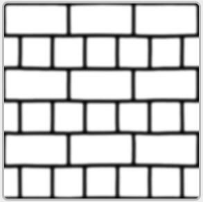
One way to do this is to take a plane with roughly 1000 vertices and displace each of these vertices based on a value in a texture that tells us the height of the plane at a specific area. Such a texture that contains height values per texel is called a height map. An example height map derived from the geometric properties of a simple brick surface looks a bit like this:
Taking a flat plane displaced with the above heightmap results in the following image:
A problem with displacing vertices is that a plane needs to consist of a large amount of triangles to get a realistic displacement otherwise the displacement looks too blocky. As each flat surface could then require over 1000 vertices this quickly becomes computationally infeasible.
2、Parallax Mapping 理论。
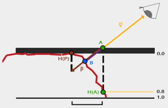
The idea behind parallax mapping is to alter the texture coordinates in such a way that it looks like a fragment's surface is higher or lower than it actually is, all based on the view direction and a heightmap.

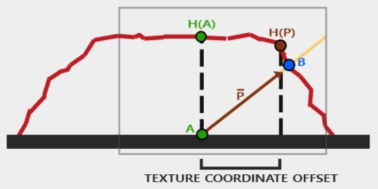
Red line represents the values in the heightmap. If the plane would have actual displacement the viewer would see the surface at point B.
Parallax mapping aims to offset the texture coordinates at fragment position A in such a way that we get texture coordinates at point B.
The trick is to figure out how to get the texture coordinates at point B from point A. Parallax mapping tries to solve this by scaling the fragment-to-view direction vector V¯ by the height at fragment A.
So we're scaling the length of V¯ to be equal to a sampled value from the heightmap H(A) at fragment position A. The image below shows this scaled vector P¯:
We then take this vector P¯P¯ and take its vector coordinates that align with the plane as the texture coordinate offset.
This works because vector P¯P¯ is calculated using a height value from the heightmap so the higher a fragment's height, the more it effectively gets displaced.
3、Parallax Mapping实现。
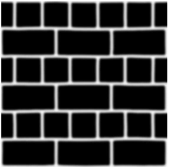
实例计算,会使用另一种模式。首先HeightMap 变成 DepthMap。DepthMap是HeightMap的取反。
其次,计算模型稍微变化:
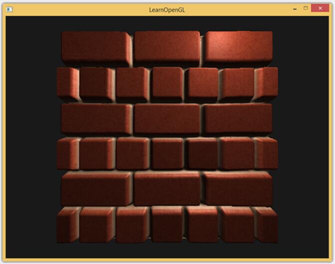
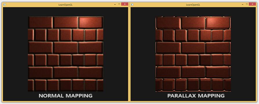
4、效果图。
5、Steep Parallax Mapping
Steep Parallax Mapping is an extension on top of Parallax Mapping in that it uses the same principles, but instead of 1 sample it takes multiple samples to better pinpoint vector P¯P¯ to BB. This gives much better results, even with steep height changes as the accuracy of the technique is improved by the number of samples.
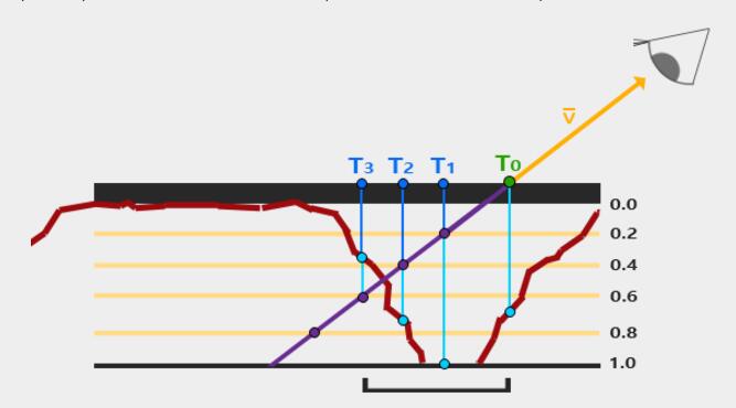
We traverse the depth layers from the top down and for each layer we compare its depth value to the depth value stored in the depthmap. If the layer's depth value is less than the depthmap's value it means this layer's part of vector P¯P¯ is not below the surface. We continue this process until the layer's depth is higher than the value stored in the depthmap: this point is then below the (displaced) geometric surface.
In this example we can see that the depthmap value at the second layer (D(2) = 0.73) is still lower than the second layer's depth value 0.4 so we continue. In the next iteration the layer's depth value 0.6 does become higher than the depthmap's sampled depth value (D(3) = 0.37). We can thus assume vector P¯ at the third layer to be the most viable position of the displaced geometry. We can then take the texture coordinate offset T3T3 from vector P3¯ to displace the fragment's texture coordinates. You can see how the accuracy increases with more depth layers.
6、Parallax Occlusion Mapping
Parallax Occlusion Mapping is based on the same principles as Steep Parallax Mapping, but instead of taking the texture coordinates of the first depth layer after a collision, we're going to linearly interpolate between the depth layer after and before the collision. We base the weight of the linear interpolation on how far the surface's height is from the depth layer's value of both layers.
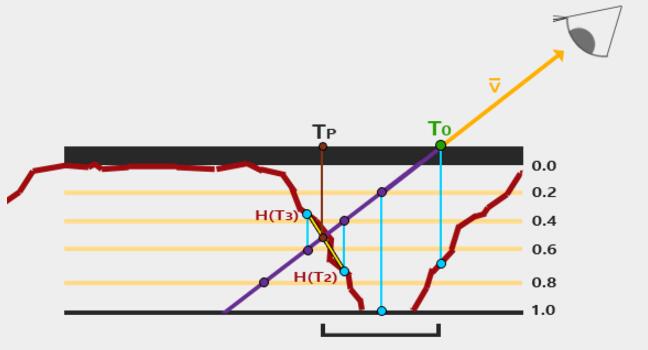
As you can see it's largely similar to Steep Parallax Mapping with as an extra step the linear interpolation between the two depth layers' texture coordinates surrounding the intersected point. This is again an approximation, but significantly more accurate than Steep Parallax Mapping.
7、Relief Mapping
ReliefMap的基本思想和ParallaxMap完全一致:就是给通过光栅化计算出的贴图坐标加上一个偏移量来确定在凹凸的表面上这个坐标应该在的位置。区别是ParallaxMap仅仅是简单的根据高度沿着视方向移动UV,这样在深度高的时候就会出现严重的走样,但是ReliefMap则是通过确定视向量和凹凸表面的交点来计算偏移量的,如下图所示:
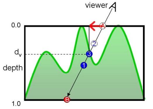
图中"点A"为光栅化计算出的贴图坐标,但因为我们的表面是凹下去的,所以摄像机看到的点应该是"点3",要实现这一点,我们就要计算出红色箭头所表示的那段偏移量,也就是要算出"点3"的坐标。
实现思想:
下面我们要做的就是确定一条从点A发出的方向为Vn的射线和这个凹凸表面的交点。这里要用到一些数值分析中的东西,就是二分法(Binary Search)和Linear Search(这东西我不知道它的中文应该是什么......)。
首先我们使用Linear Search方法确定这条射线最早同曲面所交点的大概位置,所谓LinearSearch其实就是沿着Vn方向按照一个指定的深度的步长"d"去找到那个第一个进入物体的位置所在的有根区间,如图所示:
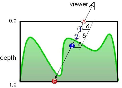
点2在表面外而点3在表面内,于是我们可以确认交点必定在点2和点3之间的这段区间上。下面我们就在这段区间中使用二分法来进一步确定交点的位置,如下图所示:

参考:
1、https://learnopengl.com/Advanced-Lighting/Parallax-Mapping
2、https://www.cnblogs.com/deepfar/archive/2008/05/31/1211276.html
Parallax Mapping的更多相关文章
- 在 OpenGL ES 2.0 上实现视差贴图(Parallax Mapping)
在 OpenGL ES 2.0 上实现视差贴图(Parallax Mapping) 视差贴图 最近一直在研究如何在我的 iPad 2(只支持 OpenGL ES 2.0, 不支持 3.0) 上实现 视 ...
- 视差贴图(Parallax Mapping)
使用顶点光照的模型,当模型的面数很少的时候,光照效果会显得很奇怪,因为只有顶点上的光照是正确计算出来的,三角面上的光照都是通过硬件插值得到,所以难免会出现问题.基于像素的光照可以很好的改善这个问题.如 ...
- Parallax Mapping Shader 凸凹感【转】
原文 http://www.azure.com.cn/default.asp?cat=11&page=2 Parallax Mapping 就是通过高度图中的高度,对纹理坐标进行偏移,来视觉上 ...
- 3D游戏图形技术解析(7)——视差映射贴图(Parallax Mapping)【转】
http://www.cnblogs.com/taotaobujue/articles/2781371.html 视差映射贴图(Parallax Mapping) ● 传统纹理贴图的弊端 纹理贴图大家 ...
- Parallax Occlusion Mapping in GLSL [转]
http://www.sunandblackcat.com/tipFullView.php?topicid=28 This lesson shows how to implement differ ...
- 切线空间(Tangent Space)法线映射(Normal Mapping)【转】
// 请注明出处:http://blog.csdn.net/BonChoix,谢谢~) 切线空间(Tangent Space) 切换空间,同局部空间.世界空间等一样,是3D图形学中众多的坐标系之一.切 ...
- [转]显卡帝揭秘3D游戏画质特效
显卡帝揭秘3D游戏画质特效 近几年来,大量采用最新技术制作的大型3D游戏让大部分玩家都享受到了前所未有的游戏画质体验,同时在显卡硬件方面的技术革新也日新月异.对于经常玩游戏的玩家来说,可能对游戏画质提 ...
- Unity3D Built-in Shader详解一
Unity3D内置了很多Shader,文档很详细,自己翻一下.便于加深印象. 首先先解释下Unity3D的Shader.Unity里面的Shaders是使用一种叫ShaderLab的语言编写的,它同微 ...
- 3D中的切线空间简介
转自:http://www.cnblogs.com/cxrs/archive/2009/10/25/1589515.html 1. 什么是Tangent space? Tangent space和wo ...
随机推荐
- 【Selenium-WebDriver自学】Selenium-IDE模式匹配(六)
==================================================================================================== ...
- MySQL C API(23)
C API 提供了对 MySQL c/s 模型的底层访问.C API 代码在 mysqlclient 库中实现.可以从该库中引用到的变量及含义: 环境变量 含义 MYSQL_UNIX_PORT 本地连 ...
- Docker Basic
1.简介 last 1.简介 1.1目的?一次编译.到处运行: 1.2.是什么? 实现[运行环境和配置文件的]软件容器,方便[持续集成]实现[整体发布]的容器虚拟化技术: 概括:整体发布的[容器虚拟化 ...
- 《算法》第二章部分程序 part 1
▶ 书中第二章部分程序,加上自己补充的代码,包括插入排序,选择排序,Shell 排序 ● 插入排序 package package01; import java.util.Comparator; im ...
- Python: 对CSV文件读写 和 Md5加密
1. python 有专门的csv包,直接导入即可. import csv: 2. 直接使用普通文件的open方法 csv_reader=open("e:/python/csv_data/l ...
- http etag
基础知识 1) 什么是”Last-Modified”? 在浏览器第一次请求某一个URL时,服务器端的返回状态会是200,内容是你请求的资源,同时有一个Last-Modified的属性 ...
- springboot 多环境选择
1.配置开发环境(开发环境) 2. application.yml 环境选择 3.cmd 切换环境 4. 设置环境调用方法 5. 另一方法
- 机器学习进阶-案例实战-图像全景拼接-图像全景拼接(RANSCA) 1.sift.detectAndComputer(获得sift图像关键点) 2.cv2.findHomography(计算单应性矩阵H) 3.cv2.warpPerspective(获得单应性变化后的图像) 4.cv2.line(对关键点位置进行连线画图)
1. sift.detectAndComputer(gray, None) # 计算出图像的关键点和sift特征向量 参数说明:gray表示输入的图片 2.cv2.findHomography(kp ...
- day09-列表
1.列表的格式list与其他语言的数组相似,基础数据类型,可以存储各种数据类型,可以存储大量的数据,32位python可以存储2的29次方个元素,即536870912个元素,64位python的限制是 ...
- PRC远程过程调用
RPC(Remote Promote Call) 一种进程间通信方式.允许像调用本地服务一样调用远程服务. RPC框架的主要目标就是让远程服务调用更简单.透明.RPC框架负责屏蔽底层的传输方式(TCP ...