
Renesas M16C/6X -- Simple PWM Signal Generation Using DMA
1. Requirements
To generate a PWM output, we need to create a train of pulses with constant period and variable duty cycle.
The duty cycle, being the modulation is the pulse width.
Typically, a timer is used to maintain both the period and duty cycle
by toggling an output based on compare matches between the timer and timer registers.
The timer is reset at the end of the pulse’s period in preparation for generating the next pulse.
In this case, the number of PWM will be limited by the number of timers that can operate in PWM mode.
This application note illustrates another method to generate the PWM outputs,
using DMA transfers to create one or two PWM signals.
This can be an advantage when a particular timer (a ‘precious resource’)
with a certain function is needed for other purposes in a design.
Instead, a simpler timer can be used.
2. DMAC Operation
The operation of DMAC on an M16C/6x device is as follows:
- DMAC is initialized with a source address, a destination address, and a number for the amount of data to be transferred.
- The DMA ‘waits’ for a request signal which can be a software or hardware trigger signal.
- After a request signal is received, one byte or one word of data is transferred from the source address to the destination address.
- Depended on the DMA settings, either the source or destination address is incremented, or both addresses stay fixed.
- After a predefined number of data is transferred, the transfer can be repeated at the beginning or stopped.
A variable PWM signal will be created since we can change the source data as we please, and thus vary the duty cycle (pulse width).
We can also change the destination address.
The train of data can be output as an external signal of the MCU if we set the destination address to a specific output port.
3. How the PWM Signal is Created
We need to continuously maintain the pulse’s period and duty cycle.
To have the DMAC maintain the period we use a timer as the DMA request factor.
In the sample application we set up a timer to cause an underflow and then request a DMA transfer.
We can fine tune the signal at the destination output pin to have any level (high or low) at any specific time in one period.
In the following reasoning, a timer period is quantified as the time interval between each timer underflow.
This is Ttimer = PWM period / PWM resolution
To achieve a certain PWM resolution, say N (e.g. 255), we must transfer data N (255) times within one PWM period.
We will operate the DMAC in repeat mode to generate a continuous train of PWM signal.
In this mode, the whole set of data at the source address will be transferred again and again after the completion of the previous one.
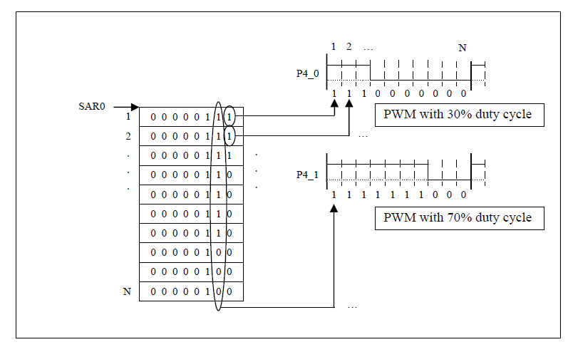
Figure 1. PWM data is through some means apart from the DMA written to the data source buffer, pointed to by SARi.
This data is periodically transferred by the DMAC so that the signals at P4 behave the same way as PWM outputs with pre-defined duty cycle.
An array of data is shown which generate a PWM signal with 30% and 70% duty cycle at pin P4_0 and P4_1.
Up to 8 separate PWM signals can easily be generated in this example, with the same amount of MCU peripherals.
As shown in Figure 1, N data is transferred by N timer interrupts, and then the process is repeated.
N is the value in the TCRi register (Transfer Counter register) and is in fact the PWM resolution.
Data is transferred from the source address (in the SAR register) to the destination address (in the DAR register), which maps to P4.
Renesas M16C/6X -- Simple PWM Signal Generation Using DMA的更多相关文章
- Control an LM317T with a PWM signal
http://www.edn.com/design/analog/4363990/Control-an-LM317T-with-a-PWM-signal The LM317T from Nationa ...
- STM32的PWM输入模式设置并用DMA接收数据
参考 :STM32输入捕获模式设置并用DMA接收数据 PWM input mode This mode is a particular case of input capture mode. The ...
- Simple PWM to Analog Circuit (0-10vdc)
i just finished this simple circuit and am very satisfied with the result. The output is very stable ...
- STM32F4 -- How to use the DMA burst feature
Bits 15:13 Reserved, must be kept at reset value. Bits 12:8 DBL[4:0]: DMA burst length This 5-bit ve ...
- PWM DAC vs. Standalone
http://analogtalk.com/?p=534 http://analogtalk.com/?p=551 Posted by AnalogAdvocate on April 09, 2010 ...
- Make a DAC with a microcontroller's PWM timer
http://www.edn.com/design/analog/4337128/Make-a-DAC-with-a-microcontroller-s-PWM-timer Many embedded ...
- Generate stabilized PWM signals
A standard technique for generating analog voltages using µCs is to use a PWM output and filter the ...
- PWM DAC Low Pass Filtering
[TI博客大赛][原创]LM3S811之基于PWM的DAC http://bbs.ednchina.com/BLOG_ARTICLE_3005301.HTM http://www.fpga4fun.c ...
- How determine the RC time constant in PWM DAC low-pass filter?
how determine the RC time constant in PWM digital to analog low-pass filter? I 'm looking for the be ...
随机推荐
- 【转】在Mac OS X 10.8中配置Apache + PHP + MySQL
CHENYILONG Blog 在Mac OS X 10.8中配置Apache + PHP + MySQL 在Mac OS X 10.8中配置Apache+PHP+MySQL的内容包括: 配置Apac ...
- 批量增加Linux系统账号、重置账号密码、FTP账号批量测试
批量增加Linux系统账号.重置账号密码是用Linux Shell脚本来做的:批量FTP账号测试是用Python脚本来做的.这些脚本都是读取一个用户名和密码文件,然后基于该用户名密码文件进行自动批量测 ...
- 有用的linux命令集锦
http://blog.csdn.net/hackerain/article/details/7946193 1. 查看内存使用情况 free -m 2. 查看系统版本信息 sudo lsb_rele ...
- Project Euler Problem4
Largest palindrome product Problem 4 A palindromic number reads the same both ways. The largest pali ...
- 去除Android APP里面的广告
如何去除Android游戏软件中的广告:很多时候,我们下载好一款Andriod游戏软件,却被游戏软件中的广告弄的很烦.不停跳动的广告让人觉得非常不爽,而且在玩游戏的时候,还有可能点击到广告,中断游戏. ...
- LeetCode(15):三数之和
Medium! 题目描述: 给定一个包含 n 个整数的数组 nums,判断 nums 中是否存在三个元素 a,b,c ,使得 a + b + c = 0 ?找出所有满足条件且不重复的三元组. 注意:答 ...
- 2016 版 Laravel 系列入门教程
2016 版 Laravel 系列入门教程 (1) - (5) http://www.golaravel.com/post/2016-ban-laravel-xi-lie-ru-men-jiao-ch ...
- 【AtCoder】AGC020
A - Move and Win 题解 看两个人相遇的时候谁先手即可,相遇之后第一个移动的人必输 代码 #include <bits/stdc++.h> #define fi first ...
- 【AtCoder】ARC089
C - Traveling 先看能不能走到,再看看奇偶性是否相同 #include <bits/stdc++.h> #define fi first #define se second # ...
- 【LOJ】#2090. 「ZJOI2016」旅行者
题解 每次按较长边把矩形分成两半,找一个中间轴,轴上的每个点跑一边最短路更新所有的答案 然后把矩形分成两半,递归下去 代码 #include <bits/stdc++.h> #define ...